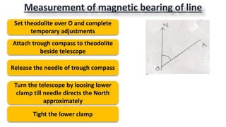
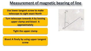
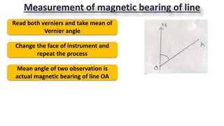
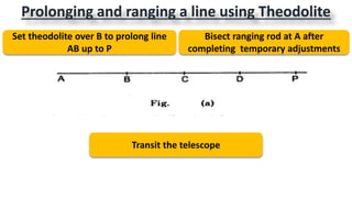
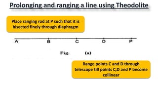
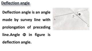
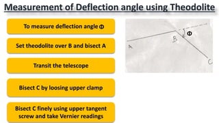
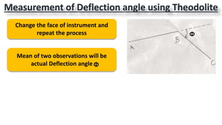
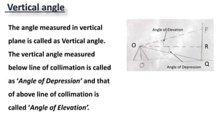
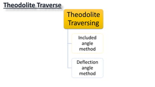
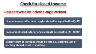
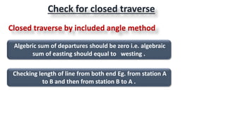
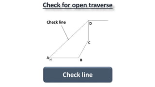
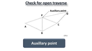
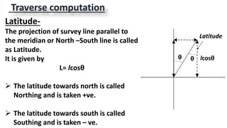
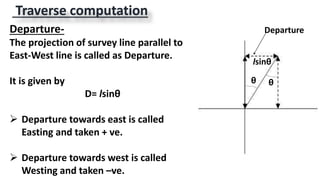
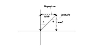
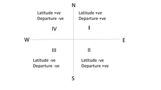
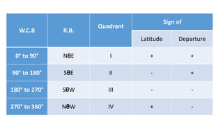
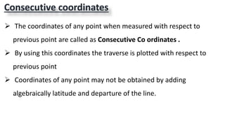
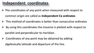
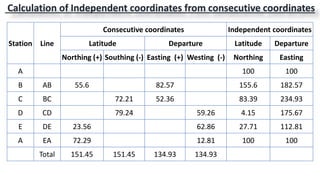
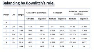
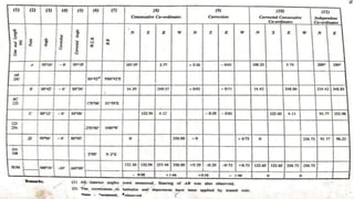
2.THEODOLITE SURVEYING
(Part 2)
By
Mr. Naufil Sayyad
Measurement of magnetic bearing of line
Set theodolite over O and complete
temporary adjustments
Attach trough compass to theodolite
beside telescope
Release the needle of trough compass
Turn the telescope by loosing lower
clamp till needle directs the North
approximately
Tight the lower clamp
Measurement of magnetic bearing of line
Use lower tangent screw to make
telescope to sight exact North
Turn telescope towards A by loosing
upper clamp and bisect A
approximately
Tight the upper clamp
Bisect A finely by using upper tangent
screw
Measurement of magnetic bearing of line
Read both verniers and take mean of
Vernier angle
Change the face of instrument and
repeat the process
Mean angle of two observation is
actual magnetic bearing of line OA
Prolonging and ranging a line using Theodolite
Set theodolite over B to prolong line
AB up to P
Bisect ranging rod at A after
completing temporary adjustments
Transit the telescope
Prolonging and ranging a line using Theodolite
Place ranging rod at P such that it is
bisected finely through diaphragm
Range points C and D through
telescope till points C,D and P become
collinear
Deflection angle
Deflection angle is an angle
made by survey line with
prolongation of preceding
line.Angle Φ in figure is
deflection angle.
Φ
Measurement of Deflection angle using Theodolite
To measure deflection angle
Set theodolite over B and bisect A
Transit the telescope
Bisect C by loosing upper clamp
Bisect C finely using upper tangent
screw and take Vernier readings
Φ
Φ
Measurement of Deflection angle using Theodolite
Change the face of instrument and
repeat the process
Mean of two observations will be
actual Deflection angle
Φ
Φ
Vertical angle
Q
RO
The angle measured in vertical
plane is called as Vertical angle.
The vertical angle measured
below line of collimation is called
as ‘Angle of Depression’ and that
of above line of collimation is
called ‘Angle of Elevation’.
Angle of Elevation
Angle of Depression
Measurement of Vertical angle using Theodolite
To measure vertical angle POR
Set theodolite over O
Level the instrument using foot
screws with respect to altitude bubble
Make zero of verniers C and D
approximately coincide to zero of
vertical circle by losing vertical clamp
RO
Measurement of Vertical angle using Theodolite
Set verniers C and D to zero exactly
using vertical tangent screw
Now line of collimation is horizontal
Bisect P approximately by losing
vertical clamp then tight it
Using vertical tangent screw bisect P
finely
Read verniers C and D
RO
Measurement of Vertical angle using Theodolite
Change the face of instrument and
repeat the process
Mean of two face readings is exact
angle POR
RO
Observation table
StationObject Face Angle
Reading on vernier
Mean
angle of
vernier
Mean angle of
observation
RemarkWindow
C
Diff
Window
D
Diff
O
R
Left POR
0°0'0" 15°0'20
"
0°0'0" 15°0'40
"
15°0'30
"
15°0'20"
Angle of
elevatio
n
P 15°0'20" 15°0'40"
O
R
Right POR
0°0'0" 15°0'20
"
0°0'0"
15°0'0"
15°0'10
"P 15°0'20" 15°0'0"
Theodolite Traverse
Theodolite
Traversing
Included
angle
method
Deflection
angle
method
Included angle method
Set theodolite on station A and carry
out all temporary adjustments
Set verniers A and B at 0° and 180 °
Set trough compass beside telescope
and lose its needle
Turn the telescope till it sights north
approximately by losing lower clamp
Sight north finely using lower tangent
screw
Included angle method
Bisect B approximately by losing upper
clamp then tight it
Bisect B exactly using upper tangent
screw
Read the verniers A and B and take
mean of verniers reading
Change the face of instrument and
repeat the process
Mean of two face observation will be
actual bearing of line AB
Included angle method
Set theodolite over station B
Measure <ABC by direct method
Similarly from station C,D and E <C,<D
and <E are measured
From included angles and bearing of
first line bearing of all lines is
obtained
Included angle method
From consecutive coordinates
independent coordinates are
calculated
With the help of independent
coordinates traverse is plotted on
paper
From these bearings and lengths of
sides consecutive coordinates are
calculated i.e. Latitude and departure
Deflection angle method
Theodolite is set on A and bearing of
line AB is measured
Then instrument is shifted on B and
deflection angle α1 is measured
To plot the open traverse ABCDE
Deflection angle method
Right hand deflection is taken as
positive
Left hand deflection is taken as
negative
Similarly by setting instrument on C,D
and E deflection angles α2, α3 and α4
are measured
Deflection angle method
Lengths of all sides are measured
From bearing of first line and
deflection angles α 1,α2, α3 and α4
bearings of remaining lines are
obtained
Sum of measured included angles should be equal to (2n-4)×90°
Sum of measured exterior angles should be equal to (2n+4)×90°
Algebric sum of latitudes should be zero i.e. algebraic sum of
northing should equal to southing.
Check for closed traverse
Closed traverse by included angle method
Algebric sum of departures should be zero i.e. algebraic
sum of easting should equal to westing .
Checking length of line from both end Eg. from station A
to B and then from station B to A .
Check for closed traverse
Closed traverse by included angle method
Check for closed traverse
Closed traverse by deflection angle method
The algebraic sum of deflection angles should be equal to
360° considering right hand deflection angles as +ve & left
hand deflection angles as –ve.
Check for open traverse
Check line
A
B
C
DCheck line
Check for open traverse
Auxillary point
A
P
B
C
D
Auxillary point
Traverse computation
Latitude-
The projection of survey line parallel to
the meridian or North –South line is called
as Latitude.
It is given by
L= lcosθ
 The latitude towards north is called
Northing and is taken +ve.
 The latitude towards south is called
Southing and is taken – ve.
lcosθθ θ
Latitude
Traverse computation
θ θ
Departure-
The projection of survey line parallel to
East-West line is called as Departure.
It is given by
D= lsinθ
 Departure towards east is called
Easting and taken + ve.
 Departure towards west is called
Westing and taken –ve.
lsinθ
Departure
θ θ
lsinθ
Departure
lcosθ
Latitude
Latitude +ve
Departure +ve
Latitude -ve
Departure +ve
Latitude -ve
Departure -ve
Latitude +ve
Departure -ve
IIV
III II
N
S
W E
W.C.B R.B.
Quadrant
Sign of
Latitude Departure
0° to 90° NθE I + +
90° to 180° SθE II - +
180° to 270° SθW III - -
270° to 360° NθW IV + -
Consecutive coordinates
 The coordinates of any point when measured with respect to
previous point are called as Consecutive Co ordinates .
 By using this coordinates the traverse is plotted with respect to
previous point
 Coordinates of any point may not be obtained by adding
algebraically latitude and departure of the line.
Independent coordinates
 The coordinates of any point when measured with respect to
common origin are called as Independent Co ordinates
 This method of coordinates is better than consecutive ordinates
 By using this coordinates the traverse is plotted with respect to
parallel and perpendicular to meridian.
 Coordinates of any point may be obtained by adding
algebraically latitude and departure of the line.
Station Line
Consecutive coordinates Independent coordinates
Latitude Departure Latitude Departure
Northing (+) Southing (-) Easting (+) Westing (-) Northing Easting
A 100 100
B AB 55.6 82.57 155.6 182.57
C BC 72.21 52.36 83.39 234.93
D CD 79.24 59.26 4.15 175.67
E DE 23.56 62.86 27.71 112.81
A EA 72.29 12.81 100 100
Total 151.45 151.45 134.93 134.93
Calculation of Independent coordinates from consecutive coordinates
The term balancing is generally applied to the
operation of applying corrections to latitudes and
departures so that algebraic sum of latitudes and
that of departures will be zero. This applies only
when the survey forms a closed polygon.
Balancing the traverse
Balancing
traverse
Bowditch’s
rule
Transit rule
Bowditch’s rule
The basis of this method is on the assumptions that the
errors in linear measurements are proportional to the length
of the line
 The rule, also termed as the compass rule, is used to
balance the traverse when the angular and linear
measurements are equally precise.
 By this rule, the total error in latitude and in departure is
distributed in proportion to the lengths of the sides.
Bowditch’s rule
This rule is most commonly used in traverse adjustment.
Correction to latitude = total error in latitude x ( length of
that side/ perimeter of traverse ).
 Correction to departure = total error in departure x ( length
of that side/ perimeter of traverse )
 If error is negative then correction is positive and vice versa.
6) After applying correction summation all latitudes and
departures must be zero.
Transit rule
 The transit rule may be employed where angular
measurements are more precise than the linear
measurements.
 According to this rule, the total error in latitudes and in
departures is distributed in proportion to the latitudes and
departures of the sides.
 It is claimed that the angles are less affected by
corrections applied by transit method than by those by
Bowditch's method.
Transit rule
The transit rule is
Correction to latitude of any side
= Total error in latitude ×Latitude of that side/ Arithmetic
sum of Latitudes
Correction to departure of any side
= Total error in departure × Departure of that side/
Arithmetic sum of Departures
Station Line Length
Consecutive coordinates
Latitutde Departure
A
B AB 30.62 43.9 27.97
C BC 15.86 -22.8 13.87
D CD 21 -32.5 -20.32
E DE 32.76 46.6 -28.14
A EA 26.6 -36.9 2.83
Total 126.8 -1.7 -3.79
Arithmetic
sum
182.7 93.13
By Bowditch’s rule
Correction to latitude of line AB
= total error in latitude x ( length of that side AB/ perimeter of
traverse )
= 1.7 x (30.62/126.84)
=0.41m
Correction to departure of line AB
= total error in departure x ( length of that side AB/ perimeter of
traverse )
= 3.79 x (30.62/126.84)
= 0.915m
By Transit rule
Correction to latitude of any side
= Total error in latitude ×Latitude of that side/ Arithmetic sum of
Latitudes
=1.7 x (43.9/182.7)
=0.41m
Correction to departure of any side
= Total error in departure × Departure of that side/ Arithmetic sum
of Departures
= 3.79 x (27.97/93.13)
=1.14m
Station Line Length
Consecutive coordinates Correction
Corrected Consecutive
coordinates
Latitutde Departure Latitude Departure Latitude Departure
A
B AB 30.62 43.9 27.97 0.41 0.915 44.31 28.885
C BC 15.86 -22.8 13.87 0.214 0.474 -22.586 14.344
D CD 21 -32.5 -20.32 0.281 0.627 -32.219 -19.693
E DE 32.76 46.6 -28.14 0.44 0.979 47.04 -27.161
A EA 26.6 -36.9 2.83 0.357 0.795 -36.543 3.625
126.8 -1.7 -3.79 1.7 3.79 0 0
Balancing by Bowditch’s rule
Gale’s Traverse table
Theodolite surveying part2

Theodolite surveying part2

  • 1.
  • 2.
    Measurement of magneticbearing of line Set theodolite over O and complete temporary adjustments Attach trough compass to theodolite beside telescope Release the needle of trough compass Turn the telescope by loosing lower clamp till needle directs the North approximately Tight the lower clamp
  • 3.
    Measurement of magneticbearing of line Use lower tangent screw to make telescope to sight exact North Turn telescope towards A by loosing upper clamp and bisect A approximately Tight the upper clamp Bisect A finely by using upper tangent screw
  • 4.
    Measurement of magneticbearing of line Read both verniers and take mean of Vernier angle Change the face of instrument and repeat the process Mean angle of two observation is actual magnetic bearing of line OA
  • 5.
    Prolonging and ranginga line using Theodolite Set theodolite over B to prolong line AB up to P Bisect ranging rod at A after completing temporary adjustments Transit the telescope
  • 6.
    Prolonging and ranginga line using Theodolite Place ranging rod at P such that it is bisected finely through diaphragm Range points C and D through telescope till points C,D and P become collinear
  • 7.
    Deflection angle Deflection angleis an angle made by survey line with prolongation of preceding line.Angle Φ in figure is deflection angle. Φ
  • 8.
    Measurement of Deflectionangle using Theodolite To measure deflection angle Set theodolite over B and bisect A Transit the telescope Bisect C by loosing upper clamp Bisect C finely using upper tangent screw and take Vernier readings Φ Φ
  • 9.
    Measurement of Deflectionangle using Theodolite Change the face of instrument and repeat the process Mean of two observations will be actual Deflection angle Φ Φ
  • 10.
    Vertical angle Q RO The anglemeasured in vertical plane is called as Vertical angle. The vertical angle measured below line of collimation is called as ‘Angle of Depression’ and that of above line of collimation is called ‘Angle of Elevation’. Angle of Elevation Angle of Depression
  • 11.
    Measurement of Verticalangle using Theodolite To measure vertical angle POR Set theodolite over O Level the instrument using foot screws with respect to altitude bubble Make zero of verniers C and D approximately coincide to zero of vertical circle by losing vertical clamp RO
  • 13.
    Measurement of Verticalangle using Theodolite Set verniers C and D to zero exactly using vertical tangent screw Now line of collimation is horizontal Bisect P approximately by losing vertical clamp then tight it Using vertical tangent screw bisect P finely Read verniers C and D RO
  • 14.
    Measurement of Verticalangle using Theodolite Change the face of instrument and repeat the process Mean of two face readings is exact angle POR RO
  • 15.
    Observation table StationObject FaceAngle Reading on vernier Mean angle of vernier Mean angle of observation RemarkWindow C Diff Window D Diff O R Left POR 0°0'0" 15°0'20 " 0°0'0" 15°0'40 " 15°0'30 " 15°0'20" Angle of elevatio n P 15°0'20" 15°0'40" O R Right POR 0°0'0" 15°0'20 " 0°0'0" 15°0'0" 15°0'10 "P 15°0'20" 15°0'0"
  • 16.
  • 17.
    Included angle method Settheodolite on station A and carry out all temporary adjustments Set verniers A and B at 0° and 180 ° Set trough compass beside telescope and lose its needle Turn the telescope till it sights north approximately by losing lower clamp Sight north finely using lower tangent screw
  • 18.
    Included angle method BisectB approximately by losing upper clamp then tight it Bisect B exactly using upper tangent screw Read the verniers A and B and take mean of verniers reading Change the face of instrument and repeat the process Mean of two face observation will be actual bearing of line AB
  • 19.
    Included angle method Settheodolite over station B Measure <ABC by direct method Similarly from station C,D and E <C,<D and <E are measured From included angles and bearing of first line bearing of all lines is obtained
  • 20.
    Included angle method Fromconsecutive coordinates independent coordinates are calculated With the help of independent coordinates traverse is plotted on paper From these bearings and lengths of sides consecutive coordinates are calculated i.e. Latitude and departure
  • 21.
    Deflection angle method Theodoliteis set on A and bearing of line AB is measured Then instrument is shifted on B and deflection angle α1 is measured To plot the open traverse ABCDE
  • 22.
    Deflection angle method Righthand deflection is taken as positive Left hand deflection is taken as negative Similarly by setting instrument on C,D and E deflection angles α2, α3 and α4 are measured
  • 23.
    Deflection angle method Lengthsof all sides are measured From bearing of first line and deflection angles α 1,α2, α3 and α4 bearings of remaining lines are obtained
  • 24.
    Sum of measuredincluded angles should be equal to (2n-4)×90° Sum of measured exterior angles should be equal to (2n+4)×90° Algebric sum of latitudes should be zero i.e. algebraic sum of northing should equal to southing. Check for closed traverse Closed traverse by included angle method
  • 25.
    Algebric sum ofdepartures should be zero i.e. algebraic sum of easting should equal to westing . Checking length of line from both end Eg. from station A to B and then from station B to A . Check for closed traverse Closed traverse by included angle method
  • 26.
    Check for closedtraverse Closed traverse by deflection angle method The algebraic sum of deflection angles should be equal to 360° considering right hand deflection angles as +ve & left hand deflection angles as –ve.
  • 27.
    Check for opentraverse Check line A B C DCheck line
  • 28.
    Check for opentraverse Auxillary point A P B C D Auxillary point
  • 29.
    Traverse computation Latitude- The projectionof survey line parallel to the meridian or North –South line is called as Latitude. It is given by L= lcosθ  The latitude towards north is called Northing and is taken +ve.  The latitude towards south is called Southing and is taken – ve. lcosθθ θ Latitude
  • 30.
    Traverse computation θ θ Departure- Theprojection of survey line parallel to East-West line is called as Departure. It is given by D= lsinθ  Departure towards east is called Easting and taken + ve.  Departure towards west is called Westing and taken –ve. lsinθ Departure
  • 31.
  • 32.
    Latitude +ve Departure +ve Latitude-ve Departure +ve Latitude -ve Departure -ve Latitude +ve Departure -ve IIV III II N S W E
  • 33.
    W.C.B R.B. Quadrant Sign of LatitudeDeparture 0° to 90° NθE I + + 90° to 180° SθE II - + 180° to 270° SθW III - - 270° to 360° NθW IV + -
  • 34.
    Consecutive coordinates  Thecoordinates of any point when measured with respect to previous point are called as Consecutive Co ordinates .  By using this coordinates the traverse is plotted with respect to previous point  Coordinates of any point may not be obtained by adding algebraically latitude and departure of the line.
  • 35.
    Independent coordinates  Thecoordinates of any point when measured with respect to common origin are called as Independent Co ordinates  This method of coordinates is better than consecutive ordinates  By using this coordinates the traverse is plotted with respect to parallel and perpendicular to meridian.  Coordinates of any point may be obtained by adding algebraically latitude and departure of the line.
  • 36.
    Station Line Consecutive coordinatesIndependent coordinates Latitude Departure Latitude Departure Northing (+) Southing (-) Easting (+) Westing (-) Northing Easting A 100 100 B AB 55.6 82.57 155.6 182.57 C BC 72.21 52.36 83.39 234.93 D CD 79.24 59.26 4.15 175.67 E DE 23.56 62.86 27.71 112.81 A EA 72.29 12.81 100 100 Total 151.45 151.45 134.93 134.93 Calculation of Independent coordinates from consecutive coordinates
  • 37.
    The term balancingis generally applied to the operation of applying corrections to latitudes and departures so that algebraic sum of latitudes and that of departures will be zero. This applies only when the survey forms a closed polygon. Balancing the traverse
  • 38.
  • 39.
    Bowditch’s rule The basisof this method is on the assumptions that the errors in linear measurements are proportional to the length of the line  The rule, also termed as the compass rule, is used to balance the traverse when the angular and linear measurements are equally precise.  By this rule, the total error in latitude and in departure is distributed in proportion to the lengths of the sides.
  • 40.
    Bowditch’s rule This ruleis most commonly used in traverse adjustment. Correction to latitude = total error in latitude x ( length of that side/ perimeter of traverse ).  Correction to departure = total error in departure x ( length of that side/ perimeter of traverse )  If error is negative then correction is positive and vice versa. 6) After applying correction summation all latitudes and departures must be zero.
  • 41.
    Transit rule  Thetransit rule may be employed where angular measurements are more precise than the linear measurements.  According to this rule, the total error in latitudes and in departures is distributed in proportion to the latitudes and departures of the sides.  It is claimed that the angles are less affected by corrections applied by transit method than by those by Bowditch's method.
  • 42.
    Transit rule The transitrule is Correction to latitude of any side = Total error in latitude ×Latitude of that side/ Arithmetic sum of Latitudes Correction to departure of any side = Total error in departure × Departure of that side/ Arithmetic sum of Departures
  • 43.
    Station Line Length Consecutivecoordinates Latitutde Departure A B AB 30.62 43.9 27.97 C BC 15.86 -22.8 13.87 D CD 21 -32.5 -20.32 E DE 32.76 46.6 -28.14 A EA 26.6 -36.9 2.83 Total 126.8 -1.7 -3.79 Arithmetic sum 182.7 93.13
  • 44.
    By Bowditch’s rule Correctionto latitude of line AB = total error in latitude x ( length of that side AB/ perimeter of traverse ) = 1.7 x (30.62/126.84) =0.41m Correction to departure of line AB = total error in departure x ( length of that side AB/ perimeter of traverse ) = 3.79 x (30.62/126.84) = 0.915m
  • 45.
    By Transit rule Correctionto latitude of any side = Total error in latitude ×Latitude of that side/ Arithmetic sum of Latitudes =1.7 x (43.9/182.7) =0.41m Correction to departure of any side = Total error in departure × Departure of that side/ Arithmetic sum of Departures = 3.79 x (27.97/93.13) =1.14m
  • 46.
    Station Line Length Consecutivecoordinates Correction Corrected Consecutive coordinates Latitutde Departure Latitude Departure Latitude Departure A B AB 30.62 43.9 27.97 0.41 0.915 44.31 28.885 C BC 15.86 -22.8 13.87 0.214 0.474 -22.586 14.344 D CD 21 -32.5 -20.32 0.281 0.627 -32.219 -19.693 E DE 32.76 46.6 -28.14 0.44 0.979 47.04 -27.161 A EA 26.6 -36.9 2.83 0.357 0.795 -36.543 3.625 126.8 -1.7 -3.79 1.7 3.79 0 0 Balancing by Bowditch’s rule
  • 47.