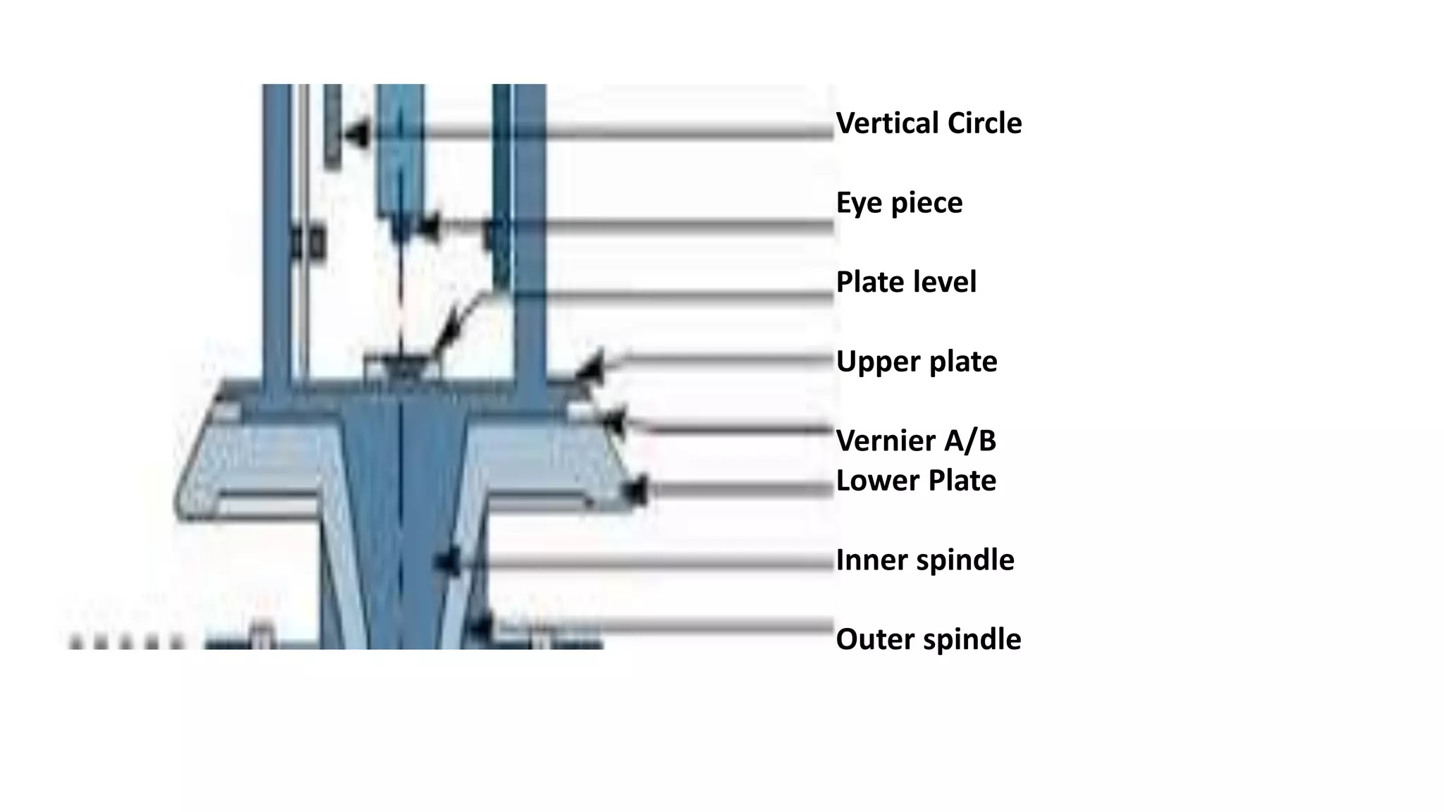
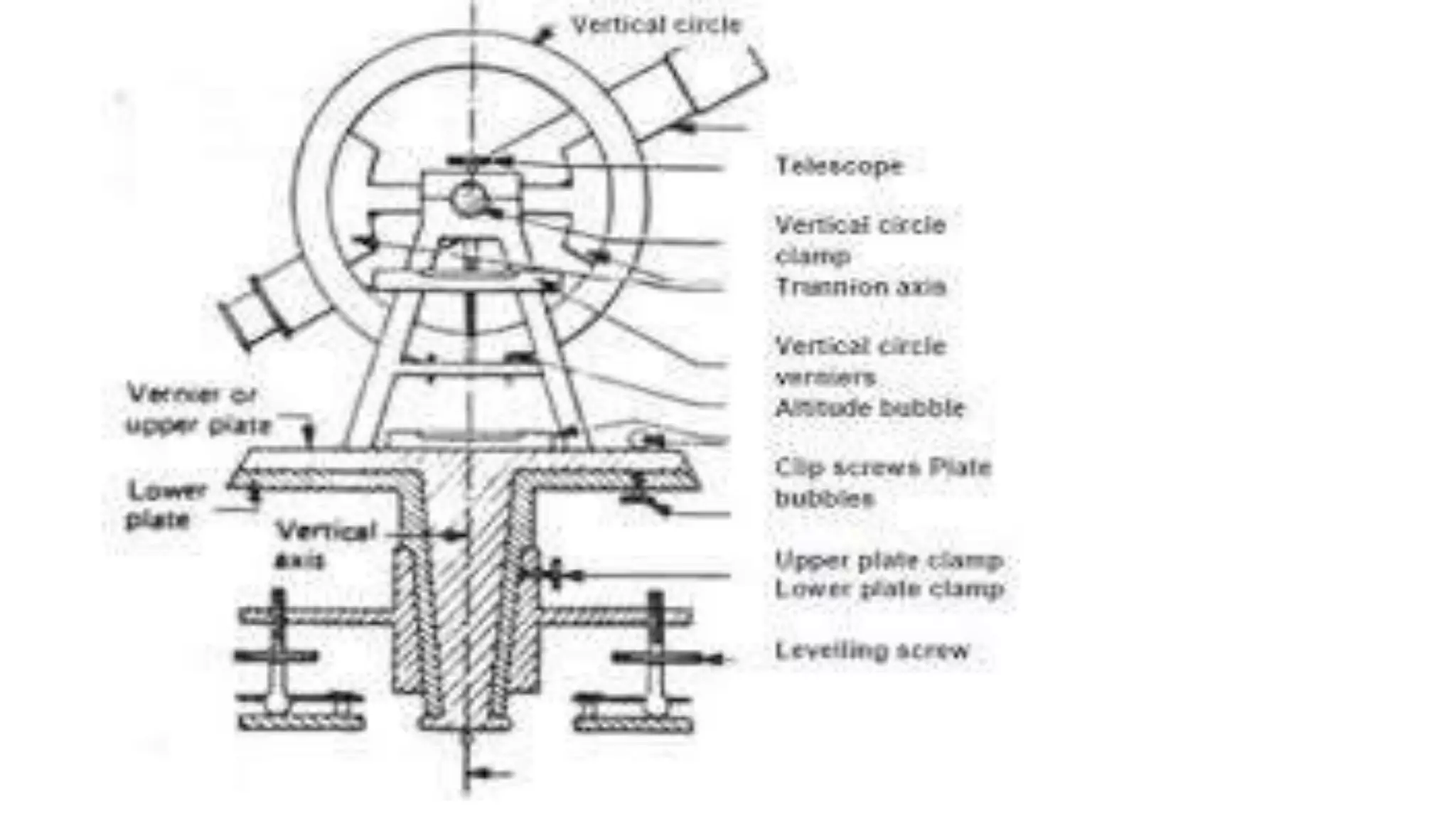
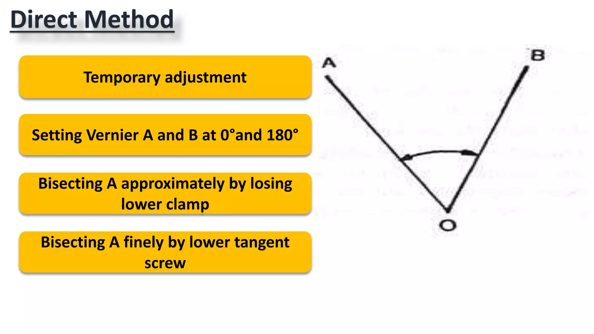
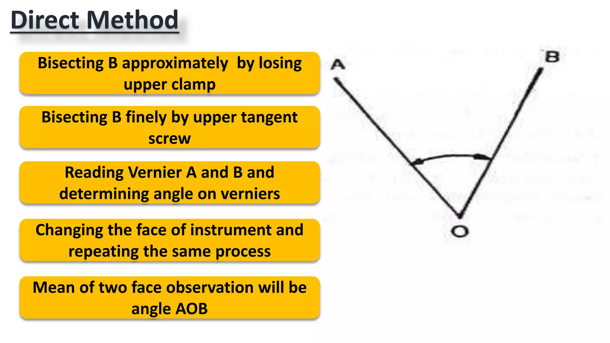
ADVANCED
SURVEYING
2.THEODOLITE SURVEYING
(24 MARKS)
By
Mr. Naufil Sayyad
Course outcome ( CO)
b. Prepare plans using Theodolite
surveys.
Practical outcomes ( PrOs)
7.Use transit
theodolite to measure
Horizontal angle
correctly by direct
method
8.Use transit
theodolite to measure
Vertical angle correctly
by direct method
9.Use transit
theodolite to measure
Horizontal angle
correctly by Repetition
method
11.Use transit
theodolite to carry out
survey project for
closed traverse for
minimum 5 sides
Unit outcomes ( UOs)
2a. Explain the given
components of the
transit theodolite
2b.describe the salient
features and relationship
between the given
fundamental axes
2c.Describe the
procedure to measure
horizontal and vertical
angles using theodolite
for the given situation
2d.Apply checks for
determining the type of
traverse using the given
data
2e.Compute latitude,
departures , consecutive
coordinates,
Independent coordinates
from given data
2f.select relevant
method of theodolite
traversing for given
condition
2g.apply Bowditch’s
rule and transit rule to
balance the traverse
for given data
2h.Tabulate Gale’s
Traverse table for the
given data
Unit outcomes ( UOs)
Introduction
Theodolite is an intricate instrument used mainly for
accurate measurement of horizontal and vertical angles up
to 10” to 20” depending upon the least count of the
instrument.
Because of its various uses the Theodolite is sometimes
known as Universal instrument.
Uses of Theodolite
1. Measurement of Horizontal angle
2. Measurement of vertical angle
3. Measurement of magnetic bearing of a line
4. Measurement of Deflection angle
5. Measuring the horizontal distance between two points
6. Finding the vertical height of an object
7. Finding difference of elevations between various points
8. Ranging a line
Types of Theodolite
Based on type of telescope
Theodolite
Transit
Non
Transit
Types of Theodolite
Based on reading unit
Theodolite
Vernier Micrometer Digital/Electronic
Vernier Theodolite
Digital/Electronic
Theodolite
Micro Optic Theodolite
Component parts of Theodolite
Telescope
Altitude bubble
Vertical
Clamping screw
Trunnion axis
Vertical Circle
Eye piece
Plate level
Upper plate
Vernier A/B
Lower Plate
Inner spindle
Outer spindle
Tribrach
Levelling screw
Trivet
Reading the Vernier of transit Theodolite
Determine the least count of the theodolite.
Suppose it is 20”.
In 20” Vernier Theodolite the main division of main scale is of 1°, which is
divided in three parts therefore each part accounts 20’.
On Vernier scale 20 main divisions each divided in 3 parts thus total 60 parts.
Least count=(d/n)=(20/60)x60=20”
Least count for one small division on Vernier=20”
Least count for one big division on Vernier= 3x20”=60”=1’.
Reading the Vernier of transit Theodolite
After making the final adjustment for measuring the angle, the position of the
arrow of Vernier scale is noted
Suppose the arrow crosses the 10°20’,this will be direct reading obtained from
the main scale
Suppose on Vernier the first small division after 12 big divisions exactly
coincides with any of the main scale division then the Vernier reading is 12’20”.
Final angle=Main scale reading + Vernier reading
=10°20’+12’20”
= 10°32’20”.
Technical terms
Swinging
 It indicates turning the telescope in the horizontal
plane.
 It is called Right swing when telescope is turned
clockwise and left swing when telescope is turned
anticlockwise.
Technical terms
Transiting
The method of turning the telescope about its
horizontal axis in a vertical plane through 180° is
termed as transiting.
In other words transiting results in change in
face.
Technical terms
Face left
Face left means the vertical circle of the
theodolite is on the left of observer at the time
of taking readings.
The observation taken in the face left position is
called as face left observation
Technical terms
Face Right
Face right means the vertical circle of the
theodolite is on the right of observer at the time
of taking readings.
The observation taken in the face right position
is called as face right observation.
Technical terms
Changing face
The operation of bringing the vertical circle
from one side of the observer to other is called
as Changing face.
Fundamental axes of Theodolite
Vertical axis
The axis of plate level (i.e. plate bubble)
Line of collimation
Horizontal axis or trunnion axis
The bubble line of altitude level ( axis of altitude
bubble)
Desired relation between fundamental lines of
Theodolite
The axis of plate level must be perpendicular to the vertical axis
The line of collimation should coincide with the optical axis of the
telescope and should also be perpendicular to the vertical axis
The horizontal axis must be perpendicular to the vertical axis
The axis of telescope must be parallel to the line of collimation
The line of collimation must be perpendicular to the horizontal axis and
the vertical circle should read zero when the line of collimation is
horizontal
Temporary adjustment of Transit Theodolite
Setting the theodolite over station
Approximate levelling by tripod stand
Centering
Levelling
Focusing the eyepiece
Focusing object glass
Setting the Vernier
Setting the Vernier of Transit Theodolitec
The upper
clamp is
loosened
upper plate is turned
until the arrow of
Vernier A
approximately coincide
with zero of the main
scale and that of
Vernier B
approximately coincide
with 180°
Then the
upper clamp is
tightened
By turning the
upper tangent
screw the arrows
are brought to
exact position of
coincidence
To set Vernier A to 0° and B at 180°
Measurement of Horizontal angle
Measurement of
Horizontal angle
Direct
Method
Repetition
Method
Points to be kept in mind
Upper plate has Vernier and lower plate has
main scale
Upper clamp is used to operate upper plate
Lower clamp is used to operate lower plate
Both upper and lower clamp has their
tangent screws for slow rotation of
instrument
When instrument is to be rotated to
measure the angle or to set the angle upper
clamp should be loosened
When instrument is to be rotated without
changing the readings lower clamp should
be loosened
Only one clamp should be loosened at a
time
Direct Method
Temporary adjustment
Setting Vernier A and B at 0°and 180°
Bisecting A approximately by losing
lower clamp
Bisecting A finely by lower tangent
screw
Direct Method
Bisecting B approximately by losing
upper clamp
Bisecting B finely by upper tangent
screw
Reading Vernier A and B and
determining angle on verniers
Changing the face of instrument and
repeating the same process
Mean of two face observation will be
angle AOB
Station Object Face
Reading
on
Vernier
Angle on
Vernier Mean angle of
Vernier
Mean angle of
observation
A B A B
O
A
Left
0°0'0" 180°0'0"
30°0'20" 30°0'0" 30°0'10"
30°0'15"
B 30°0'20" 210°0'0"
O
A
Right
0°0'0" 180°0'0"
30°0'20" 30°0'20" 30°0'20"
B 30°0'20" 210°0'20"
Observation table for Direct Method
Repetition Method
Set instrument over O and carry out
temporary adjustments
Bisect A by losing lower clamp
Here initial reading on Vernier A will
be 0°
Bisect B by losing upper clamp
Suppose here final reading on Vernier
A is 30°
Repetition Method
Again bisect A by losing lower clamp
Now here initial reading on Vernier A
will be 30°
Bisect B by losing upper clamp
Let the Final reading on Vernier A will
be 60°
Now initial reading for third
observation will be 60°
Repetition Method
Let final reading on Vernier A is 90°
This will be accumulated angle
<AOB=90°/3=30°
Repeat the process after changing face
Mean of two observations will be
actual <AOB
Statio
ns
Object Face Angle
Number of
reading
Initial Reading on
vernier
Final Reading on
vernier
Angle on vernier Mean
angle of
vernier
Mean angle
of
observation
A B A B A B
O
A
Left <AOB
1 0°0'0" 180°0'0" 30°40'0"
210°40'2
0"
30°26'46
"
30°20'6" 30°23'26"
30°23'24"
B 2 30°40'0"
210°40'2
0"
61°40'0"
240°40'2
0"
3 61°40'0"
240°40'2
0"
91°20'20" 271°0'20"
O
A
Right <AOB
1 0°0'0" 180°0'0" 30°40'20" 210°40'0"
30°26'46
"
30°20'0" 30°23'23"B 2 30°40'20" 210°40'0" 61°40'20"
240°20'4
0"
3 61°40'20"
240°20'4
0"
91°20'20" 271°0'0"
Observation table for Repetition Method
Theodolite surveying part 1 (I scheme MSBTE)

Theodolite surveying part 1 (I scheme MSBTE)

  • 1.
  • 2.
  • 3.
    Course outcome (CO) b. Prepare plans using Theodolite surveys.
  • 4.
    Practical outcomes (PrOs) 7.Use transit theodolite to measure Horizontal angle correctly by direct method 8.Use transit theodolite to measure Vertical angle correctly by direct method 9.Use transit theodolite to measure Horizontal angle correctly by Repetition method 11.Use transit theodolite to carry out survey project for closed traverse for minimum 5 sides
  • 5.
    Unit outcomes (UOs) 2a. Explain the given components of the transit theodolite 2b.describe the salient features and relationship between the given fundamental axes 2c.Describe the procedure to measure horizontal and vertical angles using theodolite for the given situation 2d.Apply checks for determining the type of traverse using the given data 2e.Compute latitude, departures , consecutive coordinates, Independent coordinates from given data
  • 6.
    2f.select relevant method oftheodolite traversing for given condition 2g.apply Bowditch’s rule and transit rule to balance the traverse for given data 2h.Tabulate Gale’s Traverse table for the given data Unit outcomes ( UOs)
  • 7.
    Introduction Theodolite is anintricate instrument used mainly for accurate measurement of horizontal and vertical angles up to 10” to 20” depending upon the least count of the instrument. Because of its various uses the Theodolite is sometimes known as Universal instrument.
  • 8.
    Uses of Theodolite 1.Measurement of Horizontal angle 2. Measurement of vertical angle 3. Measurement of magnetic bearing of a line 4. Measurement of Deflection angle 5. Measuring the horizontal distance between two points 6. Finding the vertical height of an object 7. Finding difference of elevations between various points 8. Ranging a line
  • 9.
    Types of Theodolite Basedon type of telescope Theodolite Transit Non Transit
  • 10.
    Types of Theodolite Basedon reading unit Theodolite Vernier Micrometer Digital/Electronic
  • 11.
  • 12.
  • 13.
  • 14.
    Vertical Circle Eye piece Platelevel Upper plate Vernier A/B Lower Plate Inner spindle Outer spindle
  • 15.
  • 17.
    Reading the Vernierof transit Theodolite Determine the least count of the theodolite. Suppose it is 20”. In 20” Vernier Theodolite the main division of main scale is of 1°, which is divided in three parts therefore each part accounts 20’. On Vernier scale 20 main divisions each divided in 3 parts thus total 60 parts. Least count=(d/n)=(20/60)x60=20” Least count for one small division on Vernier=20” Least count for one big division on Vernier= 3x20”=60”=1’.
  • 19.
    Reading the Vernierof transit Theodolite
  • 20.
    Reading the Vernierof transit Theodolite After making the final adjustment for measuring the angle, the position of the arrow of Vernier scale is noted Suppose the arrow crosses the 10°20’,this will be direct reading obtained from the main scale Suppose on Vernier the first small division after 12 big divisions exactly coincides with any of the main scale division then the Vernier reading is 12’20”. Final angle=Main scale reading + Vernier reading =10°20’+12’20” = 10°32’20”.
  • 21.
    Technical terms Swinging  Itindicates turning the telescope in the horizontal plane.  It is called Right swing when telescope is turned clockwise and left swing when telescope is turned anticlockwise.
  • 22.
    Technical terms Transiting The methodof turning the telescope about its horizontal axis in a vertical plane through 180° is termed as transiting. In other words transiting results in change in face.
  • 23.
    Technical terms Face left Faceleft means the vertical circle of the theodolite is on the left of observer at the time of taking readings. The observation taken in the face left position is called as face left observation
  • 24.
    Technical terms Face Right Faceright means the vertical circle of the theodolite is on the right of observer at the time of taking readings. The observation taken in the face right position is called as face right observation.
  • 25.
    Technical terms Changing face Theoperation of bringing the vertical circle from one side of the observer to other is called as Changing face.
  • 26.
    Fundamental axes ofTheodolite Vertical axis The axis of plate level (i.e. plate bubble) Line of collimation Horizontal axis or trunnion axis The bubble line of altitude level ( axis of altitude bubble)
  • 28.
    Desired relation betweenfundamental lines of Theodolite The axis of plate level must be perpendicular to the vertical axis The line of collimation should coincide with the optical axis of the telescope and should also be perpendicular to the vertical axis The horizontal axis must be perpendicular to the vertical axis The axis of telescope must be parallel to the line of collimation The line of collimation must be perpendicular to the horizontal axis and the vertical circle should read zero when the line of collimation is horizontal
  • 29.
    Temporary adjustment ofTransit Theodolite Setting the theodolite over station Approximate levelling by tripod stand Centering Levelling Focusing the eyepiece Focusing object glass Setting the Vernier
  • 31.
    Setting the Vernierof Transit Theodolitec The upper clamp is loosened upper plate is turned until the arrow of Vernier A approximately coincide with zero of the main scale and that of Vernier B approximately coincide with 180° Then the upper clamp is tightened By turning the upper tangent screw the arrows are brought to exact position of coincidence To set Vernier A to 0° and B at 180°
  • 32.
    Measurement of Horizontalangle Measurement of Horizontal angle Direct Method Repetition Method
  • 33.
    Points to bekept in mind Upper plate has Vernier and lower plate has main scale Upper clamp is used to operate upper plate Lower clamp is used to operate lower plate Both upper and lower clamp has their tangent screws for slow rotation of instrument When instrument is to be rotated to measure the angle or to set the angle upper clamp should be loosened When instrument is to be rotated without changing the readings lower clamp should be loosened Only one clamp should be loosened at a time
  • 34.
    Direct Method Temporary adjustment SettingVernier A and B at 0°and 180° Bisecting A approximately by losing lower clamp Bisecting A finely by lower tangent screw
  • 35.
    Direct Method Bisecting Bapproximately by losing upper clamp Bisecting B finely by upper tangent screw Reading Vernier A and B and determining angle on verniers Changing the face of instrument and repeating the same process Mean of two face observation will be angle AOB
  • 36.
    Station Object Face Reading on Vernier Angleon Vernier Mean angle of Vernier Mean angle of observation A B A B O A Left 0°0'0" 180°0'0" 30°0'20" 30°0'0" 30°0'10" 30°0'15" B 30°0'20" 210°0'0" O A Right 0°0'0" 180°0'0" 30°0'20" 30°0'20" 30°0'20" B 30°0'20" 210°0'20" Observation table for Direct Method
  • 37.
    Repetition Method Set instrumentover O and carry out temporary adjustments Bisect A by losing lower clamp Here initial reading on Vernier A will be 0° Bisect B by losing upper clamp Suppose here final reading on Vernier A is 30°
  • 38.
    Repetition Method Again bisectA by losing lower clamp Now here initial reading on Vernier A will be 30° Bisect B by losing upper clamp Let the Final reading on Vernier A will be 60° Now initial reading for third observation will be 60°
  • 39.
    Repetition Method Let finalreading on Vernier A is 90° This will be accumulated angle <AOB=90°/3=30° Repeat the process after changing face Mean of two observations will be actual <AOB
  • 40.
    Statio ns Object Face Angle Numberof reading Initial Reading on vernier Final Reading on vernier Angle on vernier Mean angle of vernier Mean angle of observation A B A B A B O A Left <AOB 1 0°0'0" 180°0'0" 30°40'0" 210°40'2 0" 30°26'46 " 30°20'6" 30°23'26" 30°23'24" B 2 30°40'0" 210°40'2 0" 61°40'0" 240°40'2 0" 3 61°40'0" 240°40'2 0" 91°20'20" 271°0'20" O A Right <AOB 1 0°0'0" 180°0'0" 30°40'20" 210°40'0" 30°26'46 " 30°20'0" 30°23'23"B 2 30°40'20" 210°40'0" 61°40'20" 240°20'4 0" 3 61°40'20" 240°20'4 0" 91°20'20" 271°0'0" Observation table for Repetition Method