Downloaded 459 times

![UNIFORM BUILDING BY-LAWS (Licensed to Malaysia Standards MS1525)
UBBL:
Part VIII FIRE ALARMS,FIRE DETECTIONS,FIRE EXTINGUISHMENT AND FIRE FIGHTING ACCESS
UBBL 1984 under section 238:Fire Alarms
1.Every building shall be provided with means of detecting and extinguishing fire,with means of fire alarms together with illuminated exit signs.
2.All sprinkler valves shall be located in a safe and enclosed position on the exterior wall and should be readily accessible by the Fire Authority.
UBBL 1984 under section 153:Smoke detectors for lift lobby
All lift lobbies shall be provided with smoke detectors.
UBBL 1984 under section 247(2):Fire Alarms
Main water storage tanks should be availale within the building,other than for hose reel system.Shall be located at ground,first or second basement levels,with fire brigades pumping inlet connections accessible to fire appliances
UBBL 1984 law 248:Markings on wet risers:
Wet riser,dry riser,sprinkler and other fireinstallation pipes and fittings shall be painted red.
All cabinets and areas recessed in walls for locations of fire installations and extinguishers shall be clearly identified to the Fire authority or otherwise clearly identified.
UBBLE 1984,ulaw 23:Installation and testing of wet riser systems
Wet riser systems should be provided in every building
A hose system shall be provided in each fire fighting access lobby.
Each wet riser outlet shall comprise standard 63.5mm coupling fitted with a hose of not less than 31.8mm diameter equipped with a variable fog nozzle.
According to UBBL 1984,section 227,
Portable fire extinguisher shall be provided in accordance with relevant codes of practice and shall be sited on prominent position on exit routes which shall be visible from all directions.
According to UBBL 1984:Exit Staircases
Every upper floor to have minimum 2 staircases except buildings lower than 12m
Number of Staircases should accommodate highest occupancy load under,widths of staircases and exit routes shall be maintained [not reduced in width] throughout
59](https://image.slidesharecdn.com/2-141209083415-conversion-gate02/85/Building-Services-Project-1-67-320.jpg)
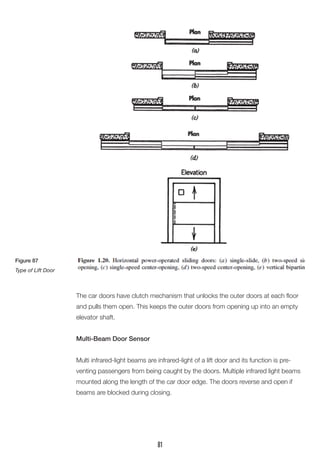

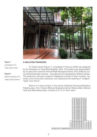
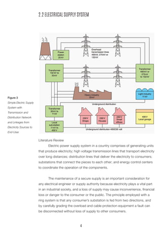
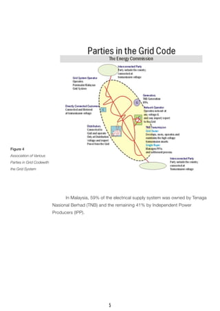
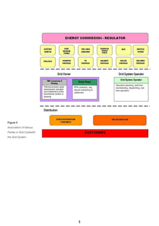
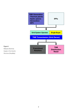
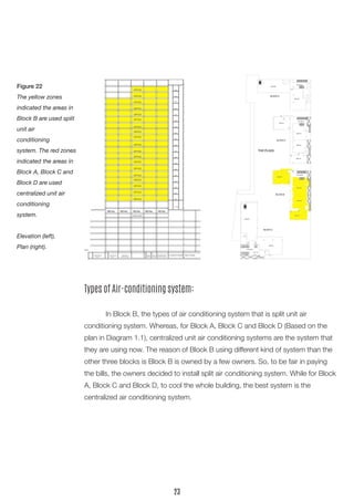
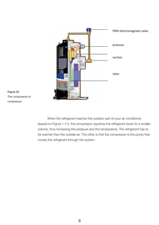
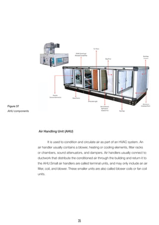
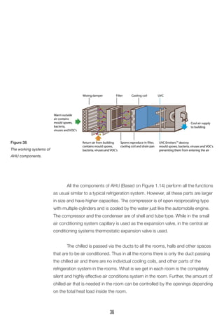
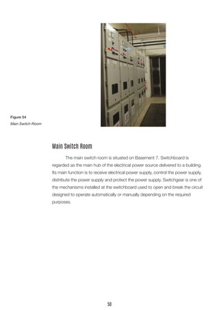
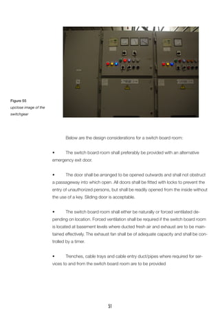
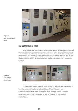
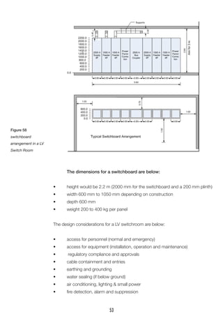
This document provides an overview of various building service systems, including mechanical ventilation, air conditioning, electrical supply, fire protection, and mechanical transportation systems. It includes literature reviews of each system that describe their functions and key components. Diagrams and case studies of each system from a building in Malaysia are also presented. The document aims to document and analyze different building service systems.


