Downloaded 12,790 times
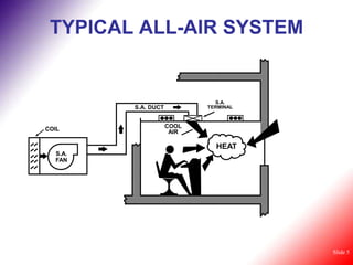
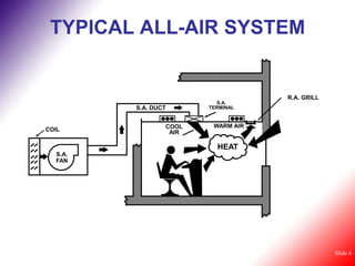
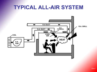
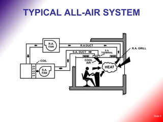
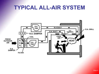
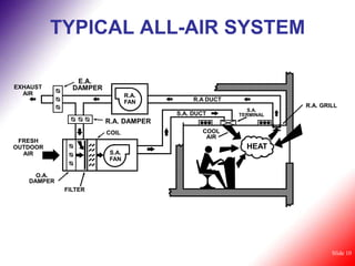
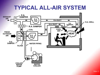
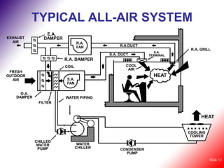
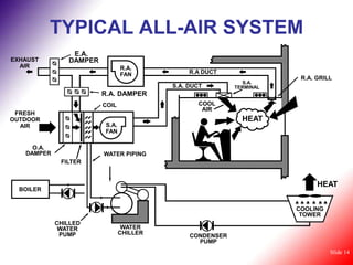
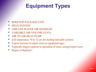


This document provides an overview of basic air conditioning concepts and typical all-air HVAC systems. It describes the major components, including coils, fans, dampers, and control systems. Typical AC units discussed are rooftop packages, split systems, chilled water air handlers, and VAV systems. The document also outlines equipment types, control types, and provides some basic rules of thumb for HVAC design and operation.


