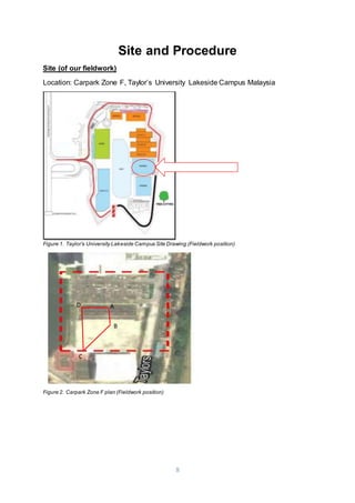
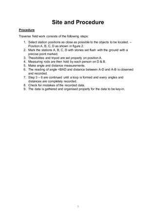
1. The document summarizes a fieldwork report on traversing conducted by 4 students at Taylor's University Lakeside Campus. They measured angles and distances between stations A, B, C, and D in the campus parking lot using a theodolite.
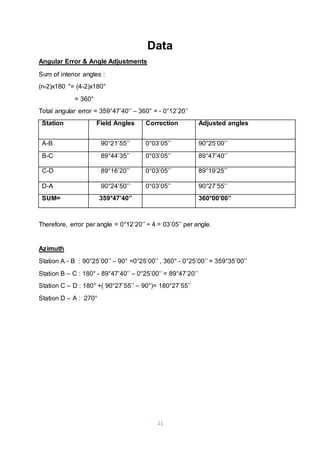
2. The data collected was used to calculate angular errors, azimuths, latitudes, departures, and station coordinates. The total misclosure error was within an acceptable range.
3. Through this fieldwork, the students gained experience using traversing instruments like theodolites and were able to obtain accurate measurements and calculate results. It provided valuable practical lessons that will benefit their future work.

![12
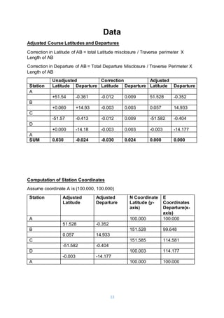
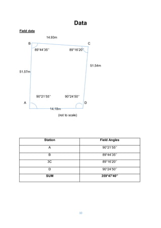
Data
Adjusted data
B C
89°47’40’’ 89°19’25’’
90°25’00’’ 90°27’55’’
A D
Computations for latitude and departure.
Accuracy = 1 : (P/Ec) , typical = 1:3000
Ec = [(sum of latitude)² + (sum of departure)² ]^½
P = Total Length
Accuracy = 1 : (132.22 / 0.038) = 1 : 3442.
Therefore , the traversing is acceptable.
Length Cos Sin Latitude Departure
Station Bearing L(m) Cos θ Sin θ L Cos θ L Sin θ
A-B N 0°25’00’’ W 51.54 1.000 0.007 +51.54 -0.361
B-C N 89°47’20’’ E 14.93 0.004 1.000 +0.060 +14.93
C-D S 0°27’55’’ W 51.57 1.000 0.008 -51.57 -0.413
D-A N 90°00’00’’ W 14.18 0.000 1.000 +0.000 -14.18
Total 132.22 0.03 -0.024](https://image.slidesharecdn.com/sitesurveyingreport2015-traversinggathered-151130125931-lva1-app6891/85/ABC-Report-123-gathered-with-reference-12-320.jpg)