Downloaded 34 times


![BQS MARCH 2014- QSB 60103 Fieldwork 2Report
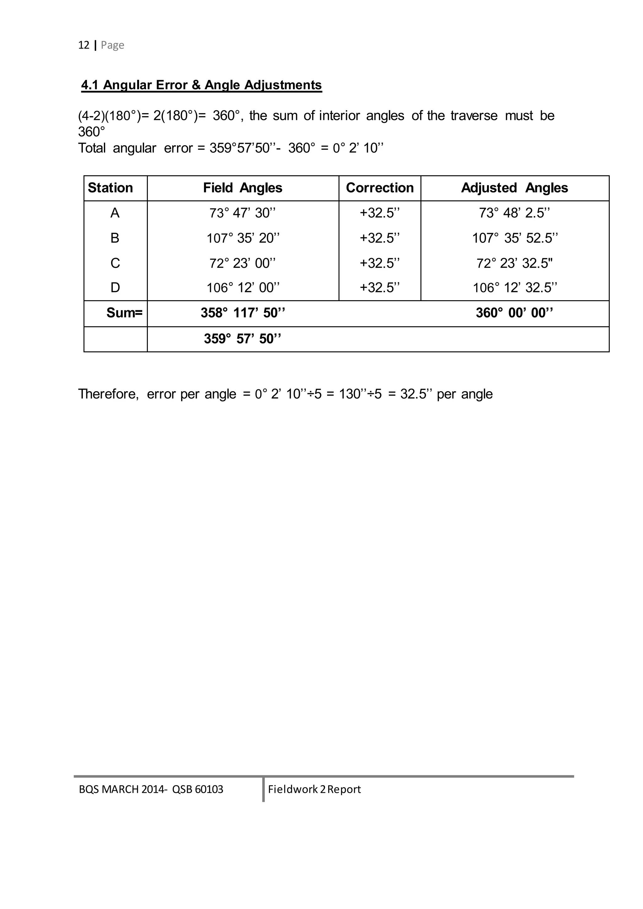
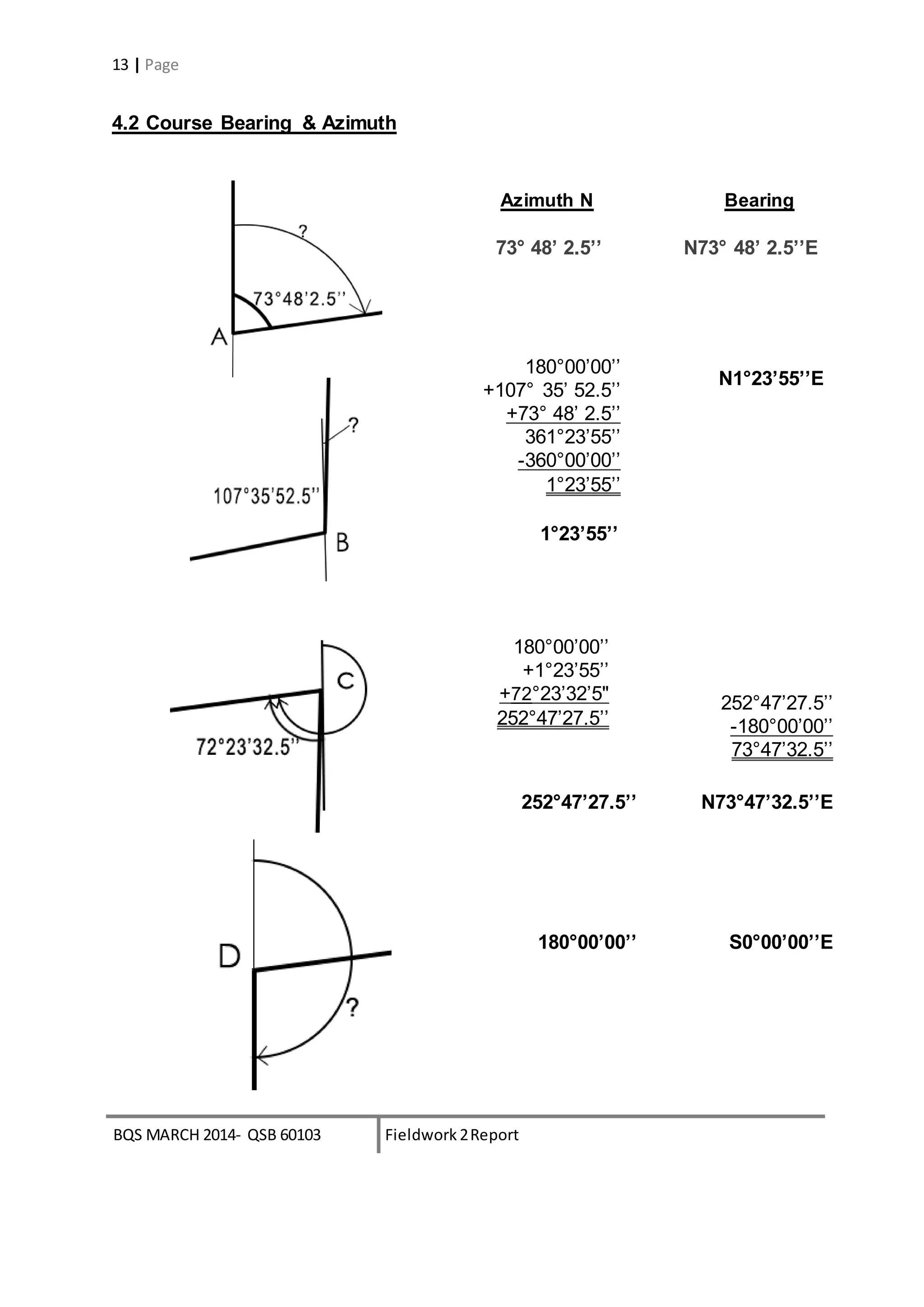
14 | Page
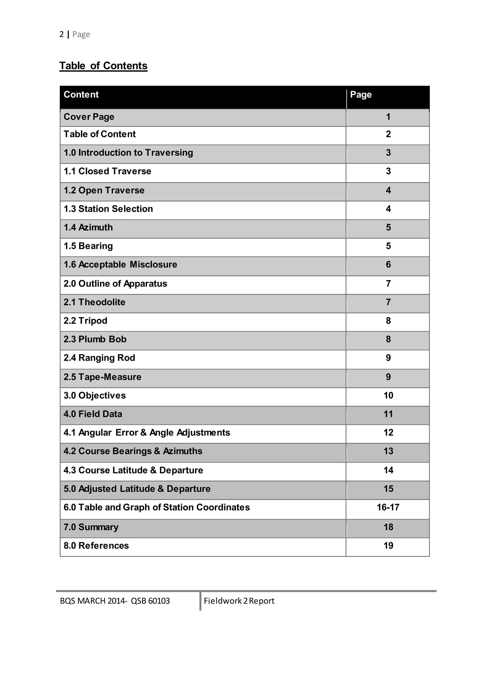
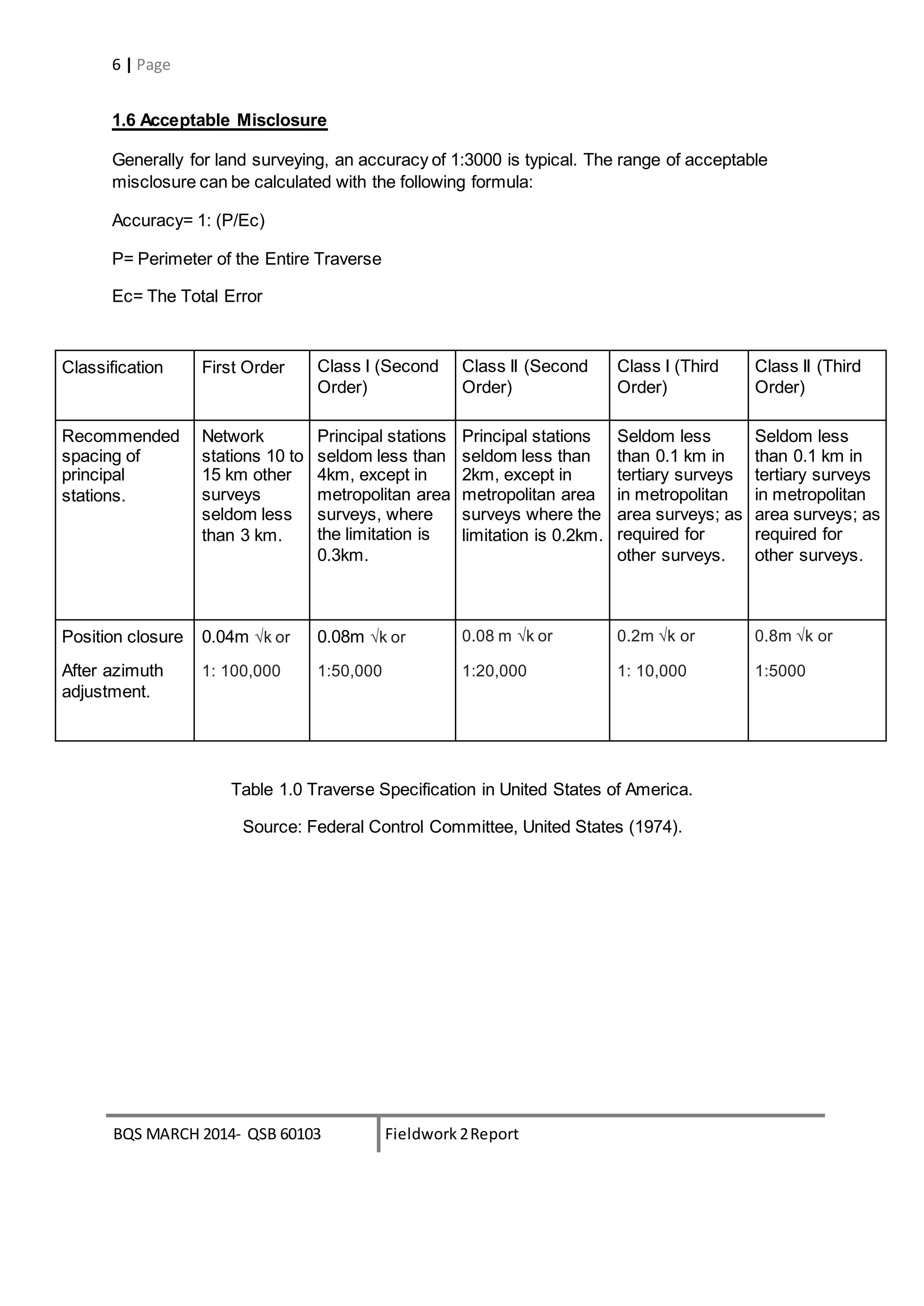
4.3 Course Latitude & Departure
Accuracy= 1 : (P/Ec), typical=1:3000
Ec = [(sum of latitude)2 + (sum of departure)2 ]1/2
= 0.045
P = 156.27
Accuracy = 1: (156.27/0.045)
= 1: 3473
∴The traversing is acceptable
cosβ sinβ Lcosβ Lsinβ
Station Bearing, β Length, L Cosine Sine Latitude Departure
A N73° 48’ 2.5’’E 12.48 0.2789795 0.9602970 +3.4819 -11.9845
B N1°23’55’’E 64.46 0.9997021 0.024407 +65.1405 +1.5899
C N73°47’32.5’’E 14.17 -0.2791421 -0.9602498 -3.9548 -13.6060
D S0°00’00’’E 65.16 -1.00000 0.00000 -64.7000 0.0000
TOTAL 156.27 -0.0324 -0.0316](https://image.slidesharecdn.com/ssreport2-141204022638-conversion-gate02-150712172910-lva1-app6891/75/Traversing-14-2048.jpg)
![BQS MARCH 2014- QSB 60103 Fieldwork 2Report
15 | Page
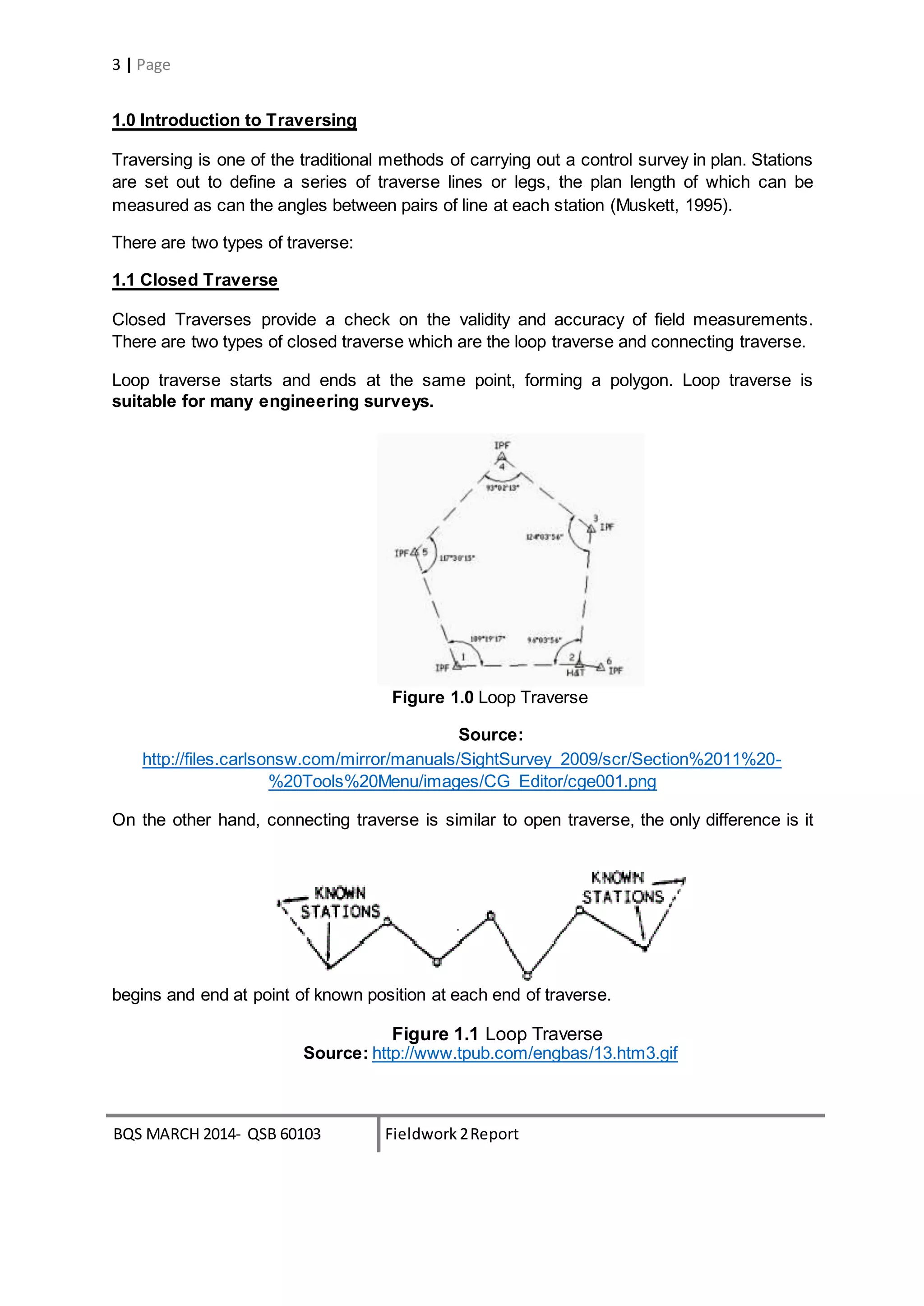
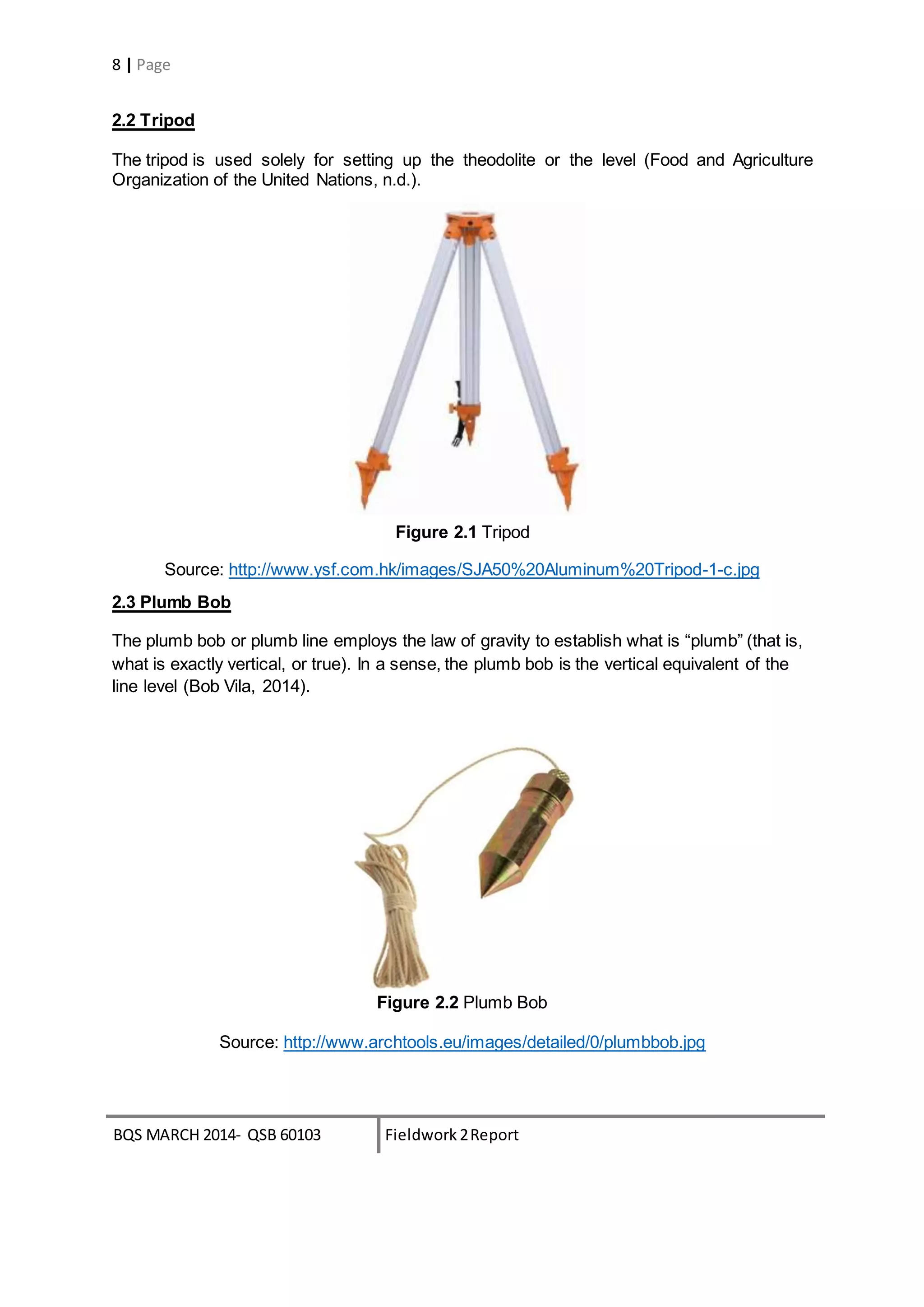
5.0 Adjusted Latitude & Departure
Compass Rule:
Correction = - [∑Δy] ÷ P x L or - [∑Δx] ÷ P x L
CorrectionAB Lat= -(-0.0324) ÷ 156.27 x 12.48
= +0.0026
CorrectionBC Lat= -(-0.0324) ÷ 156.27 x 64.46
= +0.0135
CorrectionCD Lat= -(-0.0324) ÷ 156.27 x 14.17
= +0.0029
CorrectionDA Lat= -(-0.0324) ÷ 156.27 x 65.16
= +0.0134
CorrectionAB Dep= -(-0.0316) ÷ 156.27 x 12.48
= +0.0025
CorrectionBC Dep= -(-0.0316) ÷ 156.27 x 64.46
= +0.0131
CorrectionCD Dep= -(-0.0316) ÷ 156.27 x 14.17
= +0.0029
CorrectionDA Dep= -(-0.0316) ÷ 156.27 x 65.16
= +0.0131
Unadjusted Corrections Adjusted
Station Latitude Departure Latitude Departure Latitude Departure
A +3.4819 -11.9845 +0.0026 +0.0025 +3.4845 +11.9870
B +65.1405 +1.5899 +0.0135 +0.0131 +65.1540 +1.6030
C -3.9548 -13.6060 +0.0029 +0.0029 -3.9519 -13.6031
D -64.7000 0.0000 +0.0134 +0.0131 -64.6866 +0.0131
Check -0.0324 -0.0316 +0.0324 +0.0316 0.00 0.00](https://image.slidesharecdn.com/ssreport2-141204022638-conversion-gate02-150712172910-lva1-app6891/75/Traversing-15-2048.jpg)
![BQS MARCH 2014- QSB 60103 Fieldwork 2Report
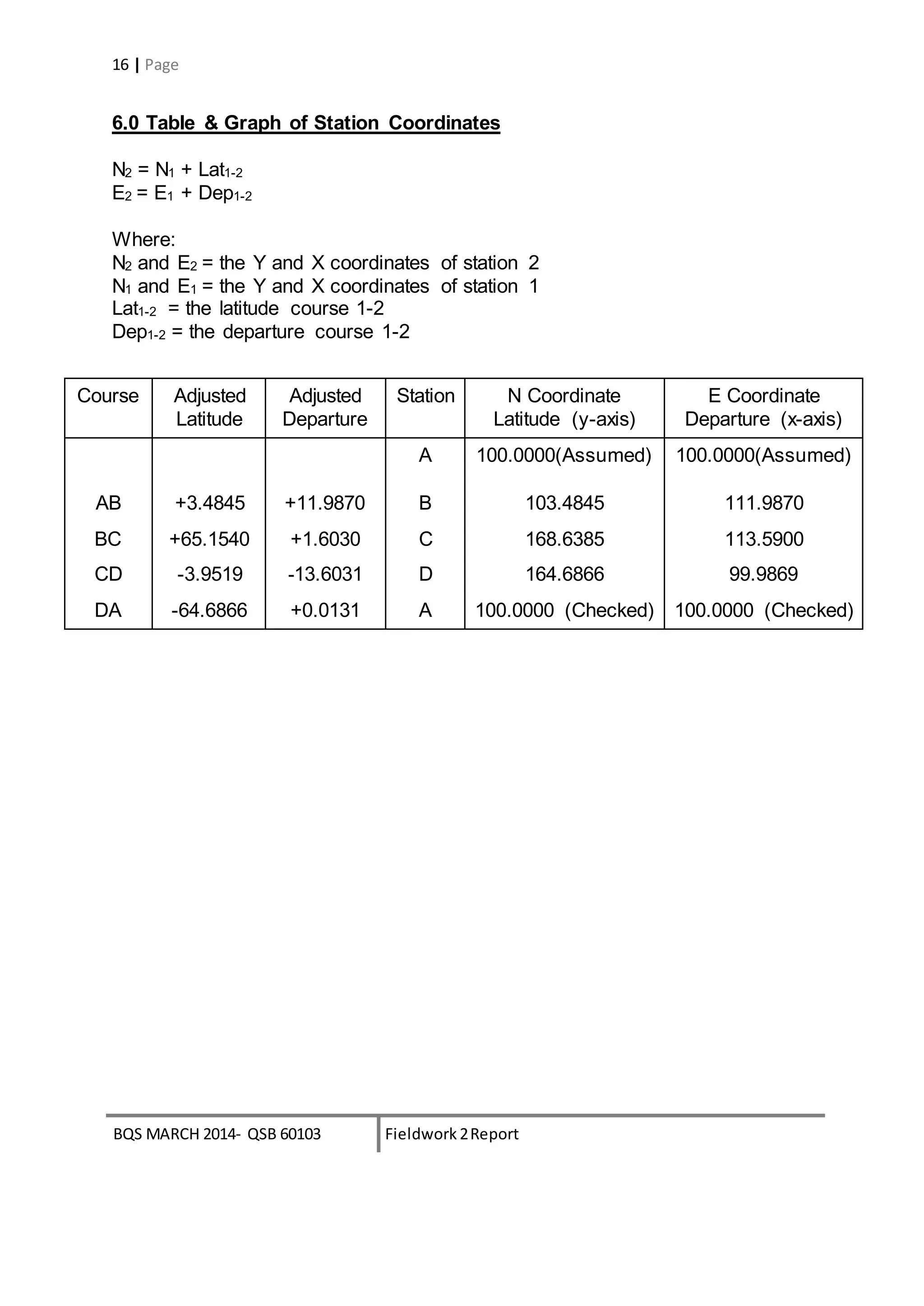
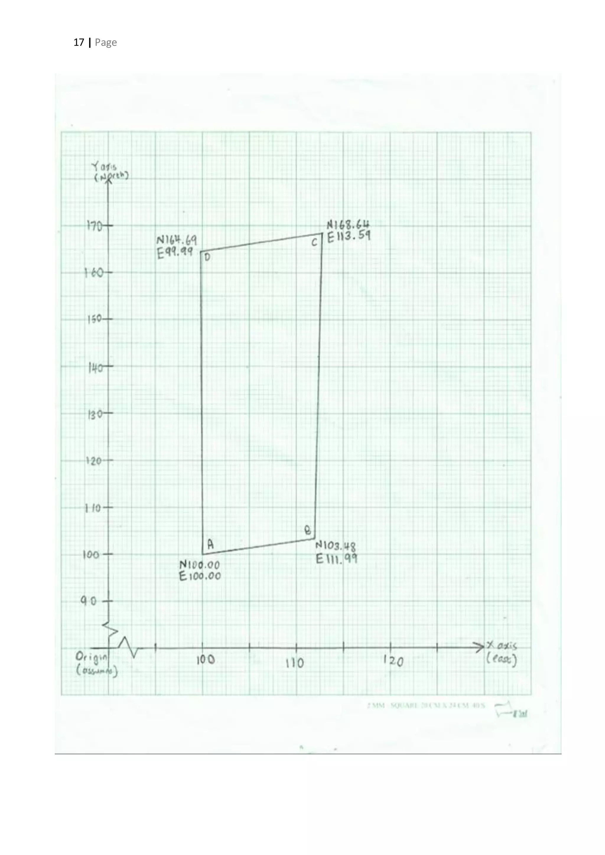
18 | Page
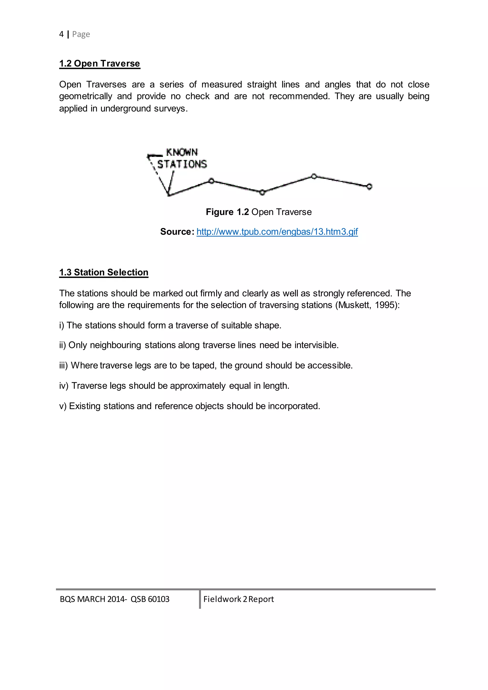
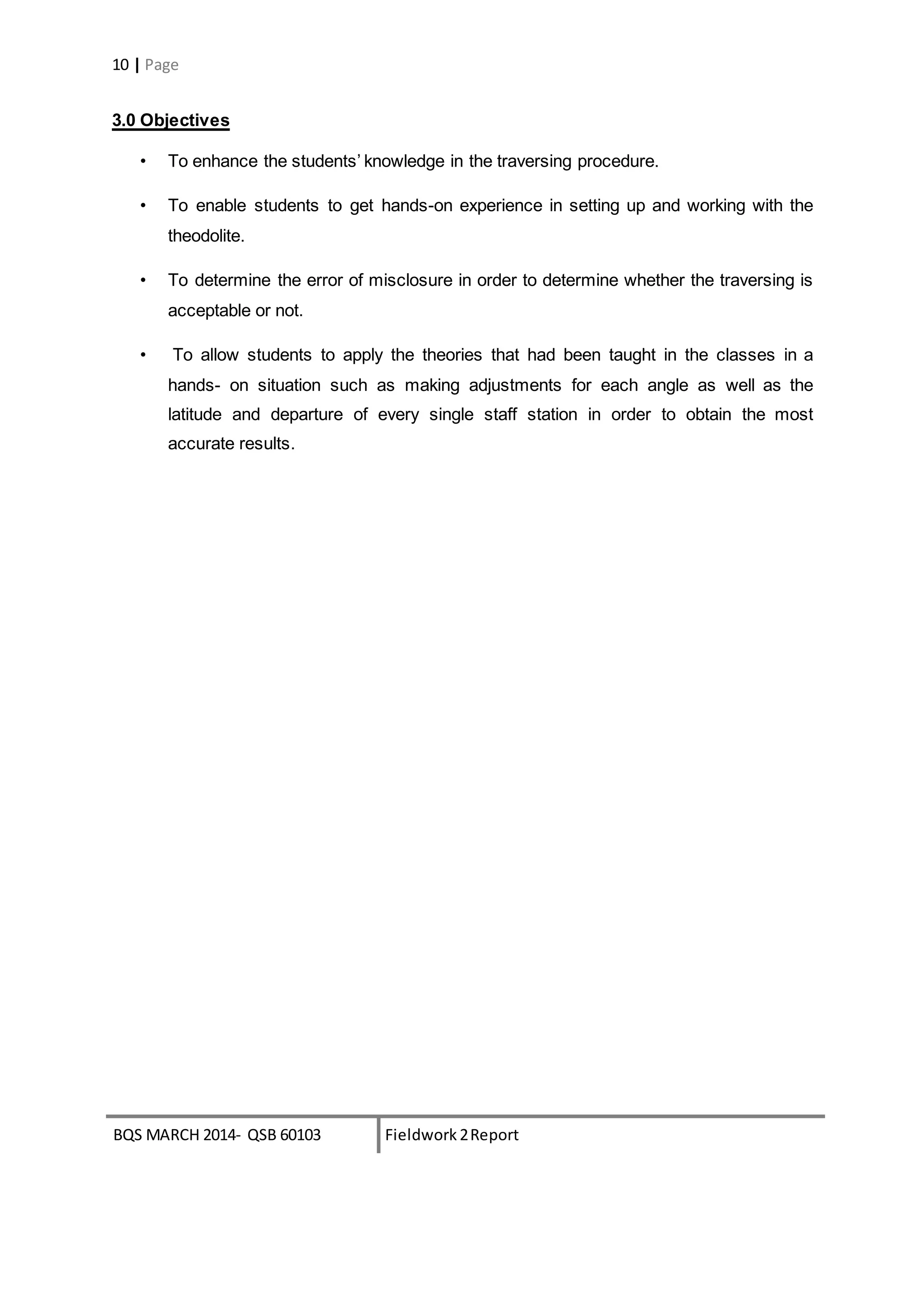
7.0 Summary
In this fieldwork, closed loop traverse is being used. For our first attempt,
we shared the theodolite with another group and used the pacing method to
obtain our length of each course but we failed to get an accuracy of at least
1:3000. For our second attempt, we used the tape-measure to measure the
length of each course. In order to get the most accurate reading possible, our
lecturer, Mr.Chai taught us to use the theodolite to guide our tape-measure to
make sure it is in a straight line.
Our error in departure is -0.0316 and our error in latitude is -0.0324. The
total error is 0.045.Using the following formula, we calculated the accuracy of
our traverse survey:
Accuracy = 1: Perimeter/ Error Closure
We obtained an accuracy of 1: 3473. For average land
surveying an accuracy of 1:3000 is typical. Therefore, our traverse survey is
acceptable.
For the adjustment of latitude and departure, we used the compass rule,
using the following formula:
Correction = - [∑Δy] ÷ P x L or - [∑Δx] ÷ P x L
Where:
∑Δy or ∑Δx = the error in latitude & departure
P = The total length or perimeter of the traverse
L = The length of the particular traverse](https://image.slidesharecdn.com/ssreport2-141204022638-conversion-gate02-150712172910-lva1-app6891/75/Traversing-18-2048.jpg)

The document summarizes a fieldwork report on traversing. It includes an introduction to closed and open traverses, station selection criteria, and apparatus used including a theodolite, tripod, plumb bob, ranging rods and tape measure. Field data is presented showing the measured angles. Angular errors are calculated and angle adjustments made. Course bearings, azimuths, latitudes and departures are determined. The traverse is checked for accuracy and found acceptable. Latitude and departure corrections are applied using the compass rule. Adjusted station coordinates are presented in a table.


![[DSC Europe 25] Debmalya Biswas - Agentification: the art of transforming man...](https://cdn.slidesharecdn.com/ss_thumbnails/r5azlggvtqiaiiusrqdr-4-251212103249-5a12c89b-thumbnail.jpg?width=640&height=640&fit=bounds)

![[DSC Europe 25] Nikolay Burlutskiy - Best Practices for Building Enterprise M...](https://cdn.slidesharecdn.com/ss_thumbnails/uirvaiuvq8y1w8hzd9tx-7-251212103249-2619edb4-thumbnail.jpg?width=640&height=640&fit=bounds)


![[DSC Europe 25] Kaja Kandare - LLM as a judge.pptx](https://cdn.slidesharecdn.com/ss_thumbnails/arxyccaxsdsd1ba99wjw-7-251212104007-2b4e3f64-thumbnail.jpg?width=640&height=640&fit=bounds)
![[DSC Europe 25] Jovan Bogicevic - Legacy to AI-Driven Defense: Transforming D...](https://cdn.slidesharecdn.com/ss_thumbnails/rsarluadt563hntyfc8q-3-251211083849-3e7bc4c0-thumbnail.jpg?width=640&height=640&fit=bounds)
![[DSC Europe 25] Bassam Maharmeh - Artificial Intelligence: Opportunities and ...](https://cdn.slidesharecdn.com/ss_thumbnails/thhfmr2fqpawzj7hsjpg-5-251211083048-2c23204f-thumbnail.jpg?width=640&height=640&fit=bounds)


![[DSC Europe 25] Tatevik Maytesyan - How to actually use AI in marketing: gett...](https://cdn.slidesharecdn.com/ss_thumbnails/tjo626lsqdgfntbgl2mw-4-251216103155-e36cd239-thumbnail.jpg?width=640&height=640&fit=bounds)


