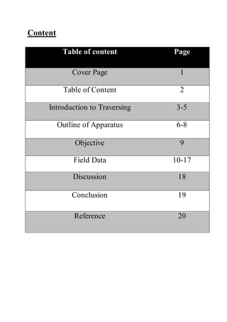
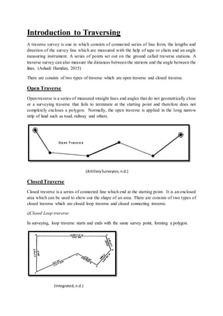
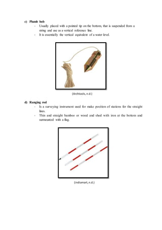
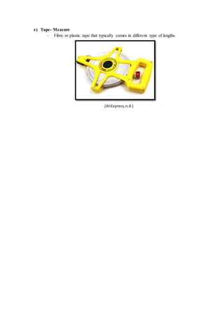
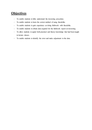
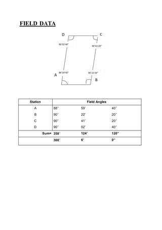
This document provides details on a fieldwork report for a traversing exercise conducted by students. It includes an introduction to traversing, descriptions of the equipment used including a theodolite, tripod, plumb bob and ranging rod. The objectives and field data from the exercise are presented. Calculations are shown for angular errors and adjustments, determining lengths using stadia measurements, and calculating latitudes, departures and station coordinates. Small errors were found and corrected using compass rule adjustments. The summary provides an acceptable level of accuracy and demonstrates the techniques learned for conducting a traversing survey.

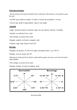
![Course Latitude & Departure
Accuracy= 1 : (P/Ec), typical=1:3000
Ec = [(sum of latitude)2 + (sum of departure)2 ]1/2
= (0.0102 2 + 0.03032)½
=0.03197
P = 98.085
Accuracy = 1: (98.085/0.03197)
= 1: 3068
∴The traversing is acceptable.
Station Bearing, β Length, L
Cosine,
Cos β
Sine,
Sin β
Latitude,
Lcosβ
Departur,
Lsinβ
A N88’58’10’E 28.9956 0.0179856 0.9998382 0.5215 28.9909
B N0°41’0’’W 19.6969 0.9999288 0.0119261 19.6955 0.2349
C S89°58’50’’W 29.1956 0.0003394 0.999999942 -0.0099 -29.1955
D S0°00’00’’E 20.1969 1 0 -20.1969 0
Total 98.085 0.0102 0.0303](https://image.slidesharecdn.com/final-1-150710165421-lva1-app6891/85/Project-2-traversing-13-320.jpg)
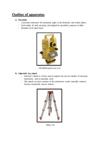
![Adjusted Latitude & Departure
Compass Rule:
Correction = - [∑Δy] ÷ P x L or - [∑Δx] ÷ P x L
Correction AB Lat= - (0.0102) ÷ 98.085x 28.9956
= -0.0030
Correction BC Lat= - (0.0102) ÷ 98.085x 19.6969
= -0.0021
Correction CD Lat= - (0.0102) ÷ 98.085x 29.1956
= -0.0030
Correction DA Lat= - (0.0102) ÷ 98.085x 20.1969
= -0.0021
Correction AB Dep= - (0.0303) ÷ 98.085x 28.9956
= -0.0090
Correction BC Dep= - (0.0303) ÷ 98.085x 19.6969
= -0.0061
Correction CD Dep= - (0.0303) ÷ 98.085x 29.1956
= -0.0090
Correction DA Dep= - (0.0303) ÷ 98.085x 20.1969
= -0.0062
Unadjusted Corrections Adjusted
Station Latitude Departure Latitude Departure Latitude Departure
A 0.5215 28.9909 -0.0030 -0.0090 +0.5185 +28.9819
B 19.6955 0.2349 -0.0021 -0.0061 +19.6934 +0.2288
C -0.0099 -29.1955 -0.0030 -0.0090 -0.0129 -29.2045
D -20.1969 0.0000 -0.0021 -0.0062 -20.1990 -0.0062
Check -0.0102 -0.0303 -0.0102 -0.0303 0.00 0.00](https://image.slidesharecdn.com/final-1-150710165421-lva1-app6891/85/Project-2-traversing-14-320.jpg)
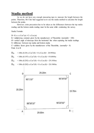
![Discussion
From this field work, we learnt to conduct a transverse survey by using a theodolite
and several formulas that we learnt from the site surveying subject. We applied the technique
and knowledge taught by Mr Chai.
Commonly, there will be errors in every site survey. For average land surveying an
accuracy of about 1:3000 is typical. Therefore, by applying correct technique and skill, we
successfully achieved the accuracy about 1:3068.
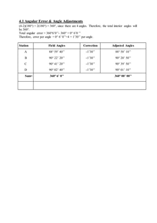
Our angular error that we obtained is of a 360° is 0° 6’ 0’’. A 0°1’30’’ of correction is
needed to be reduced to every angle. By determining the bearing we are able to calculate the
error. The error in latitude is -0.0100 while error in departure is -0.0303.
Since the error is acceptable to proceed to use the Compass Rule:
Correction= - [∑Δy] ÷ P x L or - [∑Δx] ÷ P x L to adjust the error exist in the latitude and
departure, where:
∑Δy or ∑Δx = the error in latitude & departure
P = the total length or perimeter of the traverse
L = the length of the particular traverse
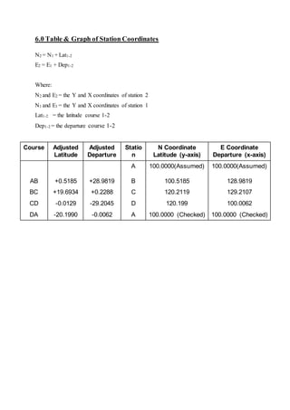
Finally, we tabulated the data and adjusted the all data and manage to present it in the
Graph of Station Coordinates.](https://image.slidesharecdn.com/final-1-150710165421-lva1-app6891/85/Project-2-traversing-16-320.jpg)