Download to read offline


![Course Latitude & Departure
Station Bearing, β
Length,
L
Cosine
( cos β )
Sine
( sin β )
Latitude
( L cos β )
Departure
( L sin β )
A S 83˚33'15" E 34.00m 0.11226 0.99368 - 3.82 + 33.79
B N 10˚12'30" W 38.00m 0.98417 0.17723 + 37.40 - 6.73
C S 78˚23'15" W 27.00m 0.20129 0.97953 - 5.43 - 26.45
D S 00˚00'00" E 28.00m - 1.00000 0.00000 - 28.00 + 0.00
Total 127.00m 0.15 0.61
Accuracy = 1 : ( P / Ec ), typical = 1:3000
Ec = [ (sum of latitude)2 + (sum of departure)2 ]1/2
= 0.628
P = 127.00
Accuracy = 1 : ( 127.00 / 0.621 )
= 1 : 202
∴The traversing is acceptable](https://image.slidesharecdn.com/ssreport2-150711150601-lva1-app6892/75/Ss-report-2-11-2048.jpg)
![Adjusted Latitude & Departure
Compass Rule:
Correction = - [∑Δy] ÷ P x L or - [∑Δx] ÷ P x L
Correction AB Lat = - ( 0.15 ) ÷ 127.00 x 34.00
= - 0.04
Correction BC Lat = - ( 0.15 ) ÷ 127.00 x 38.00
= - 0.05
Correction CD Lat = - ( 0.15 ) ÷ 127.00 x 27.00
= - 0.03
Correction DA Lat = - ( 0.15 ) ÷ 127.00 x 28.00
= - 0.03
Correction AB Dep = - ( 0.61) ÷ 127.00 x 34.00
= - 0.16
Correction BC Dep = - ( 0.61 ) ÷ 127.00 x 38.00
= - 0.18
Correction CD Dep = - ( 0.61 ) ÷ 127.00 x 27.00
= - 0.13
Correction DA Dep = - ( 0.61 ) ÷ 127.00 x 28.00
= - 0.14
Unadjusted Correction Adjusted
Station Latitude Departure Latitude Departure Latitude Departure
AB - 3.82 + 33.79 - 0.04 - 0.16 - 3.86 + 33.63
BC + 37.40 - 6.73 - 0.05 - 0.18 + 37. 35 - 6.91
CD - 5.43 - 26.45 - 0.03 - 0.13 - 5.46 - 26.58
DA - 28.00 + 0.00 - 0.03 - 0.14 - 28.03 - 0.14
Check + 0.15 + 0.61 - 0.15 - 0.61 0.0 0.0](https://image.slidesharecdn.com/ssreport2-150711150601-lva1-app6892/75/Ss-report-2-12-2048.jpg)


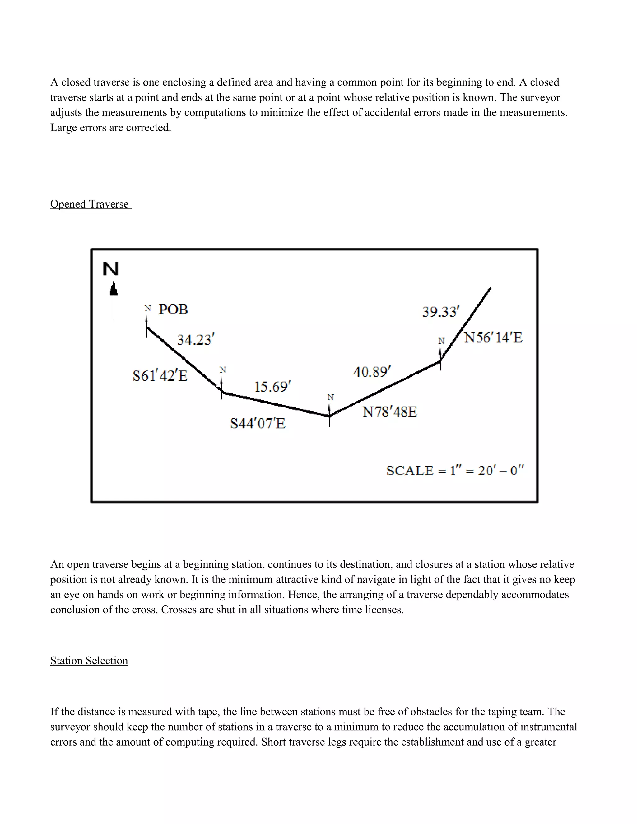
The fieldwork report details a closed traverse survey conducted by students using a theodolite. Measurements of angles and distances were taken at stations A through D. The total angular error was 0.27' and distributed evenly among measured angles. Course directions and lengths were calculated. The total error of 0.15 latitude and 0.61 departure fell within the acceptable accuracy of 1:202. Coordinates were determined for each station after applying compass rule corrections. The closed traverse allowed students to apply surveying skills and techniques learned in class.