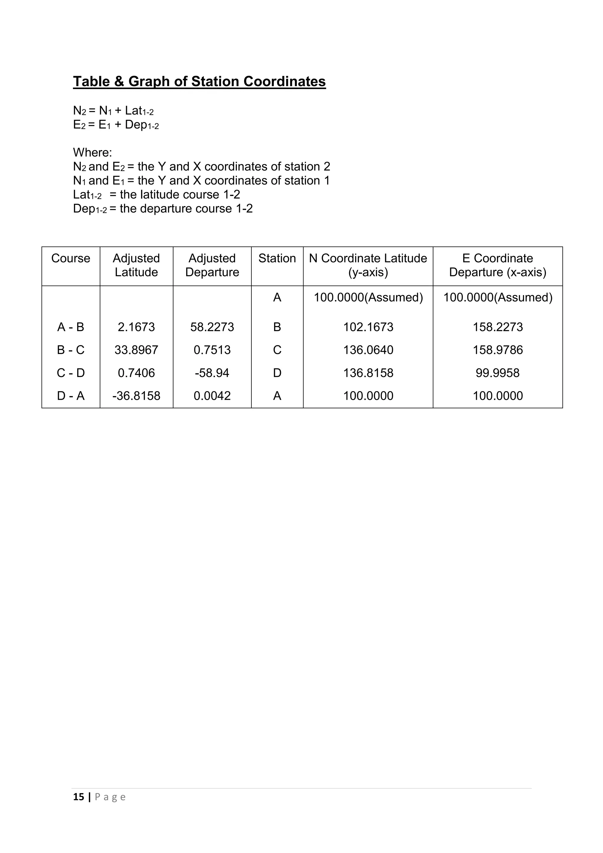
Report Assignment 2 for Site Surveying module which requires us to do Traversing measurement around the campus carpark, for the Bachelor of Quantity Surveying (BQS) Course Semester 2, Taylor's University Lakeside Campus
Plane and Applied Surveying 2
Traversing Theory Part
Traverse Computations
Definition
Types of Meridian
Applications of traversing
Bearings
Correction for observed angles (closed traverse)
Check angular Misclosure
Adjust angular Misclosure
Calculate adjusted bearings
Compute (E, N) for each traverse line
Coordinates.
-Traversing
Methods of conducting Traverse
1. Theodolite
2. Total Station
2. Compass
3. GPS
Bearings
Bearings
Bearing is the angle which a certain line make with a
certain meridian. Bearing with respect to true meridian is
called true bearings while magnetic bearing is the angle
which a line makes with respect to magnetic meridian.
There are two ways to represent the bearings,
Fore and back bearings
Whole circle bearing (W.C.B) ,(Azimuth)
Reduced Bearing (R.B) or quadrant bearing
6 The bearing of a line measured in the forward direction of survey line is called the ‘Fore Bearing’ (FB) of that line.
The bearing of the line measured in the direction opposite to the direction
of the progress of survey is called the ‘Back Bearing’ (BB) of the line.
BB= FB ± 180°
+ sign is applied when FB is < 180°
- sign is applied when FB is > 180°
1) Whole Circle Bearing (W.C.B) (Azimuth)
Is the bearing always measured from north in clockwise direction to a point.
Whole Circle Bearing (W.C.B) (Azimuth)
2) Reduced Bearing
Reduced bearing or Quadrant bearing is the angle which a line
makes from North or South Pole whichever may be near. The value of angle is from 0° to 90° , and are taken either clock wisely or anti clock wisely.
-Quadrant bearing
The difference between the whole circle bearing and quadrant
bearing are as follows.
-Example The following fore bearings were observed for lines, AB, BC, CD, and DE Determine their back bearings: • 145°, 285°, 65°, 215°
Example The Fore Bearing of the following lines are given Find the
Back Bearing.
(a) FB of AB= 310° 30’
(b) FB of BC= 145° 15’
(c) FB of CD = 210° 30’
(d) FB of DE = 60° 45’
Example:
Convert the following whole circle bearing to quadrant or
reduced bearings :
( i ) 42ᵒ 30’ ( ii ) 126ᵒ 15’
( iii ) 242ᵒ 45’ ( iv ) 328ᵒ10’
Example
Convert the following reduced bearings to whole circle
bearings:
( I ) N 65ᵒ 12’ E ( ii ) S 36ᵒ 48’ E
( iii ) S 38ᵒ 18’ W ( iv ) N 26ᵒ 32’ W
Closed Traverse
• Ends at a known point with known direction Geometrical Constraints
-Adjust the deflection angles
2-Interior angles Traverse
Interior angles are measured clockwise or counterclockwise between two adjacent lines on the inside of a closed polygon figure.
Example
The following traverse have five sides with five internal
angles. Find the angular misclosure and apply the angle
correction
-3-Exterior angle Traverse
Correction for observed angles (closed traverse)
Example:
IF ∑observed angles for traverse (ABCDA)= 360˚00′ 48″ find misclosure and correct the interior angles. Check Allowable Angle Misclosure
Prepared by:Asst. Prof. Salar K.Hussein
Erbil Polytechnic University
In this lecture we will cover
Applications of levelling
Equipment and procedures
Purposes of levelling
Some definitions
Applications
Longitudinal sections and cross sections
Plotting the profile
Procedure of profile
Procedure of cross-section:
Plotting the cross-section:
Prepared by:
Asst. Prof. Salar K.Hussein
Mr. Kamal Y.Abdullah
Asst.Lecturer. Dilveen H. Omar
Erbil Polytechnic University
Technical Engineering College
Civil Engineering Department
Traversing Notes |surveying II | Sudip khadka Sudip khadka
Traverse is a method in the field of surveying to establish control networks. It is also used in geodesy. Traverse networks involve placing survey stations along a line or path of travel, and then using the previously surveyed points as a base for observing the next point
Operation “Blue Star” is the only event in the history of Independent India where the state went into war with its own people. Even after about 40 years it is not clear if it was culmination of states anger over people of the region, a political game of power or start of dictatorial chapter in the democratic setup.
The people of Punjab felt alienated from main stream due to denial of their just demands during a long democratic struggle since independence. As it happen all over the word, it led to militant struggle with great loss of lives of military, police and civilian personnel. Killing of Indira Gandhi and massacre of innocent Sikhs in Delhi and other India cities was also associated with this movement.
This is a presentation by Dada Robert in a Your Skill Boost masterclass organised by the Excellence Foundation for South Sudan (EFSS) on Saturday, the 25th and Sunday, the 26th of May 2024.
He discussed the concept of quality improvement, emphasizing its applicability to various aspects of life, including personal, project, and program improvements. He defined quality as doing the right thing at the right time in the right way to achieve the best possible results and discussed the concept of the "gap" between what we know and what we do, and how this gap represents the areas we need to improve. He explained the scientific approach to quality improvement, which involves systematic performance analysis, testing and learning, and implementing change ideas. He also highlighted the importance of client focus and a team approach to quality improvement.
Students, digital devices and success - Andreas Schleicher - 27 May 2024..pptxEduSkills OECD
Andreas Schleicher presents at the OECD webinar ‘Digital devices in schools: detrimental distraction or secret to success?’ on 27 May 2024. The presentation was based on findings from PISA 2022 results and the webinar helped launch the PISA in Focus ‘Managing screen time: How to protect and equip students against distraction’ https://www.oecd-ilibrary.org/education/managing-screen-time_7c225af4-en and the OECD Education Policy Perspective ‘Students, digital devices and success’ can be found here - https://oe.cd/il/5yV
The Indian economy is classified into different sectors to simplify the analysis and understanding of economic activities. For Class 10, it's essential to grasp the sectors of the Indian economy, understand their characteristics, and recognize their importance. This guide will provide detailed notes on the Sectors of the Indian Economy Class 10, using specific long-tail keywords to enhance comprehension.
For more information, visit-www.vavaclasses.com
Unit 8 - Information and Communication Technology (Paper I).pdfThiyagu K
This slides describes the basic concepts of ICT, basics of Email, Emerging Technology and Digital Initiatives in Education. This presentations aligns with the UGC Paper I syllabus.
Synthetic Fiber Construction in lab .pptxPavel ( NSTU)
Synthetic fiber production is a fascinating and complex field that blends chemistry, engineering, and environmental science. By understanding these aspects, students can gain a comprehensive view of synthetic fiber production, its impact on society and the environment, and the potential for future innovations. Synthetic fibers play a crucial role in modern society, impacting various aspects of daily life, industry, and the environment. ynthetic fibers are integral to modern life, offering a range of benefits from cost-effectiveness and versatility to innovative applications and performance characteristics. While they pose environmental challenges, ongoing research and development aim to create more sustainable and eco-friendly alternatives. Understanding the importance of synthetic fibers helps in appreciating their role in the economy, industry, and daily life, while also emphasizing the need for sustainable practices and innovation.
The French Revolution, which began in 1789, was a period of radical social and political upheaval in France. It marked the decline of absolute monarchies, the rise of secular and democratic republics, and the eventual rise of Napoleon Bonaparte. This revolutionary period is crucial in understanding the transition from feudalism to modernity in Europe.
For more information, visit-www.vavaclasses.com
How to Make a Field invisible in Odoo 17Celine George
It is possible to hide or invisible some fields in odoo. Commonly using “invisible” attribute in the field definition to invisible the fields. This slide will show how to make a field invisible in odoo 17.
The Roman Empire A Historical Colossus.pdfkaushalkr1407
The Roman Empire, a vast and enduring power, stands as one of history's most remarkable civilizations, leaving an indelible imprint on the world. It emerged from the Roman Republic, transitioning into an imperial powerhouse under the leadership of Augustus Caesar in 27 BCE. This transformation marked the beginning of an era defined by unprecedented territorial expansion, architectural marvels, and profound cultural influence.
The empire's roots lie in the city of Rome, founded, according to legend, by Romulus in 753 BCE. Over centuries, Rome evolved from a small settlement to a formidable republic, characterized by a complex political system with elected officials and checks on power. However, internal strife, class conflicts, and military ambitions paved the way for the end of the Republic. Julius Caesar’s dictatorship and subsequent assassination in 44 BCE created a power vacuum, leading to a civil war. Octavian, later Augustus, emerged victorious, heralding the Roman Empire’s birth.
Under Augustus, the empire experienced the Pax Romana, a 200-year period of relative peace and stability. Augustus reformed the military, established efficient administrative systems, and initiated grand construction projects. The empire's borders expanded, encompassing territories from Britain to Egypt and from Spain to the Euphrates. Roman legions, renowned for their discipline and engineering prowess, secured and maintained these vast territories, building roads, fortifications, and cities that facilitated control and integration.
The Roman Empire’s society was hierarchical, with a rigid class system. At the top were the patricians, wealthy elites who held significant political power. Below them were the plebeians, free citizens with limited political influence, and the vast numbers of slaves who formed the backbone of the economy. The family unit was central, governed by the paterfamilias, the male head who held absolute authority.
Culturally, the Romans were eclectic, absorbing and adapting elements from the civilizations they encountered, particularly the Greeks. Roman art, literature, and philosophy reflected this synthesis, creating a rich cultural tapestry. Latin, the Roman language, became the lingua franca of the Western world, influencing numerous modern languages.
Roman architecture and engineering achievements were monumental. They perfected the arch, vault, and dome, constructing enduring structures like the Colosseum, Pantheon, and aqueducts. These engineering marvels not only showcased Roman ingenuity but also served practical purposes, from public entertainment to water supply.
Read| The latest issue of The Challenger is here! We are thrilled to announce that our school paper has qualified for the NATIONAL SCHOOLS PRESS CONFERENCE (NSPC) 2024. Thank you for your unwavering support and trust. Dive into the stories that made us stand out!
Palestine last event orientationfvgnh .pptxRaedMohamed3
An EFL lesson about the current events in Palestine. It is intended to be for intermediate students who wish to increase their listening skills through a short lesson in power point.
1. 1 | P a g e
SCHOOL OF ARCHITECTURE, BUILDING AND
DESIGN
BACHELOR OF QUANTITY SURVEYING (HONOURS)
QSB 60103- SITE SURVEYING
Fieldwork 2 Report
Traversing
Name Student ID Marks
LEE KIM THIAM 0310710
LEE CHUN YEE 0321748
LEE PEI GIE 0315653
LEE KIT HUNG 0315722
2. 2 | P a g e
Table of Content
Content Page
Cover Page 1
Table of Content 2
A. Introduction 3 - 5
B. Outline of Apparatus 6 - 7
i) Theodolite 6
ii) Adjustable Leg-Tripod 6
iii) Plumb Bob 6
iv) Ranging Rod 7
v) Measuring Tape 7
C. Objectives 8
D. Field Data 9 - 15
E. Conclusion 16
3. 3 | P a g e
A. Introduction
Traversing is the most common type of control survey. In engineering work, it is
used to locate topographic detail for preparation of plan, locate engineering works
and process and order earthwork. A traverse consists of an interconnected series of
lines called courses, running between a series of points on the ground called
traverse stations. Therefore, a traverse also known as a series of established station
tied together by angle and distances.
The accuracy of traverses is dependable to the instruments or equipment and
measuring techniques. For first class traverse, the maximum misclosure or allowable
misclosure is 1’15” and the fractional error is 1:8000. However, for second class
traverse, the maximum misclosure is 2’30” and the fractional linear error is 1:4000.
The control traverse we conducting should be a first class traverse.
4. 4 | P a g e
Closed Traverse
Closed Traverse provides a check on the validity and accuracy of field
measurements. There are two types of types of closed traverse which are loop
traverse and connecting traverse.
Loop traverse starts and ends at the same point, forming a polygon. Loop
traverse is suitable for many engineering surveys. On the other hand, connecting
traverse is similar to open traverse, the only difference is it begins and end at point of
known position at each end of traverse.
5. 5 | P a g e
Open Traverse
Open Traverses are a series of measured straight lines and angles that do not
close geometrically provide no check and are not recommended. They are usually
being applied in underground surveys.
Traverse computations include the following:
1. Compute the angular error and adjust angles
2. Compute course bearing or azimuths
3. Compute course latitudes and departures
4. Determine error of closure and accuracy; if unacceptable, the redo traverse or
parts of traverse. If acceptable, move to step 5.
5. Adjust course latitudes and departures
6. Compute station coordinates
6. 6 | P a g e
B. Outline of Apparatus
1. Theodolite
2. Adjustable Leg Tripod
Source :
(http://all-surveying.com/product_images/o/771/South_ET-
05_Survey_Electronic_Theodolite_(5_Second_Accuracy)__935
05_zoom.jpg)
A surveying instrument and precision instrument for measuring
angles in the horizontal and vertical planes. ( Zeki, n.d.).
Source :
(http://www.vsaservicesindia.com/images/products/accessories/l
arge/1.jpg )
Adjustable-leg tripods is easy to set up on ground because each
leg can be adjusted to exactly the height needed to find level,
even on a steep slope (Johnson Level,2010).
Source :
(https://thescarletthreaddotcom.files.wordpress.com/2012/05/plu
mbbob.jpg )
Instrument to ensure that the construction is plumb or verticle.
3. Plumb Bob
7. 7 | P a g e
4. Ranging rod
5. Measuring Tape
Source : (http://3.imimg.com/data3/GB/KF/MY-
5667764/ranging-rod-250x250.jpg )
Instruments to trace out lines on the ground.
Source :
(http://ecx.images-
amazon.com/images/I/61BioavRfkS._SL1170_.jpg )
A flexible ruler to measure distance.
8. 8 | P a g e
C. Objective
1. To enable students to get hands-on experience in setting up the working with
the theodolite.
2. To determine the error of disclosure in order to determine whether the
traversing is acceptable.
3. To allow students to apply theories learnt in classes in a hands-on situation
such as making adjustments for each angle as well as the latitude and
departure of every single staff station to obtain the most accurate result.
4. To enhance students’ knowledge on traversing procedure.
9. 9 | P a g e
D. Field Data
Station Field Angles
A 88° 10’ 49’’
B 93° 39’ 20’’
C 89° 05’ 31’’
D 90° 13’ 00’’
Sum= 361° 08’ 40’’
(not to scale)
Station D
Station A
Station C
Station B
10. 10 | P a g e
Angular Error & Angle Adjustments
Formula: (n - 2) (180)
= (4 - 2) (180°)
= 2 (180°)
= 360°
Total angular error = 361° 08' 40" - 360°
= 1° 08’ 40’’
Therefore, error per angle = 1° 08’ 40’’÷ 4
= 0° 17’ 10’’ per angle
Station Field Angles Correction Adjusted Angles
A 88° 10' 49" -0° 17’ 10’’ 87°53’39"
B 93° 39' 20" -0° 17’ 10’’ 93°22'10"
C 89° 05' 31" -0° 17’ 10’’ 88°48'21"
D 90° 13' 00" -0° 17’ 10’’ 89°55'50"
Sum 361° 08’ 40” 360° 0’ 0”
11. 11 | P a g e
Course Bearing & Azimuth
Station A – B
S0° 00’ 00’’W180° 00’ 00’’
N89° 55’ 50’’W1° 15’ 49’’
88°48'21"
+180° 00’ 00’’
270° 04’ 10’’
93° 22' 10"
+87° 53' 39"
181° 15’ 49’’
-180° 00’ 00’’
1° 15’ 49’’
N1° 15’ 49’’E
Stations Azimuth N Bearing
87° 53’ 39"
90° 09’ 00’’
-93° 14’ 50’’
3° 14’ 50’’
-
N87° 53’ 39’’E
Station B – C
Station C – D
Station D – A
12. 12 | P a g e
Course Latitude & Departure
Accuracy= 1: (P/Ec), where typical accuracy=1:3000
Ec = [(sum of latitude) 2 + (sum of departure) 2] 1/2
= [(-0.0829)2 + (-0.0214) 2]1/2
= 0.0856
P = 187.92
Accuracy = 1: (197.92/0.0856)
= 1: 2195
∴The traversing is acceptable
cosβ sinβ Lcosβ Lsinβ
Station Azimuth, β Length, L Cosine Sine Latitude Departure
A – B 87° 53’ 39" 58.26 0.0367455 0.9993247 +2.1408 +58.2207
B – C 1° 15’ 49’’ 33.89 0.9997568 0.0220523 +33.8817 +0.7474
C – D 270° 04’ 10’’ 58.95 0.0121220 -0.9999999 +0.7146 -58.9467
D - A 180° 00’ 00’’ 36.82 -1.0000000 0.0000000 -36.8200 +0.000
TOTAL 187.92 -0.0829 -0.0214
13. 13 | P a g e
Adjusted Latitude & Departure
Compass Rule
Latitude
Correction AB = - (-0.0829) ÷ 187.92x 58.26
= +0.0265
Correction BC = - (-0.0829) ÷ 187.92x 33.89
= +0.0150
Correction CD = - (-0.0829) ÷ 187.92x 58.95
= +0.0260
Correction DA = - (-0.0829) ÷ 187.92x 36.82
= +0.0162
Departure
Correction AB = - (-0.0214) ÷ 187.92x 58.26
= +0.0066
Correction BC = - (-0.0214) ÷ 187.92x 33.89
= +0.0039
Correction CD = - (-0.0214) ÷ 187.92x 58.95
= +0.0067
Correction DA = - (-0.0214) ÷ 187.92x 36.82
= +0.0042
Unadjusted Corrections Adjusted
Station Latitude Departure Latitude Departure Latitude Departure
A +2.1408 +58.2207 +0.0265 +0.0066 2.1673 58.2273
B +33.8817 +0.7474 +0.0150 +0.0039 33.8967 0.7513
C +0.7146 -58.9467 +0.0260 +0.0067 0.7406 -58.94
D -36.8200 +0.000 +0.0162 +0.0042 -36.8158 0.0042
Check -0.0829 -0.0214 +0.0837 +0.0214 0.00 0.00
14. 14 | P a g e
Transit Rule
Latitude
Correction AB = - (-0.0829) ÷ 73.6204x 2.1408
= +0.0024
Correction BC = - (-0.0829) ÷ 73.6204x 33.8817
= +0.0380
Correction CD = - (-0.0829) ÷ 73.6204x 0.7146
= +0.0008
Correction DA = - (-0.0829) ÷ 73.6204x -36.8200
= -0.0415
Departure
Correction AB = - (-0.0214) ÷ 117.9228x 58.2207
= +0.0106
Correction BC = - (-0.0214) ÷ 117.9228x 0.7474
= +0.0001
Correction CD = - (-0.0214) ÷ 117.9228x -58.9467
= -0.0107
Correction DA = - (-0.0214) ÷ 117.9228x 0.000
= +0.0000
Unadjusted Corrections Adjusted
Station Latitude Departure Latitude Departure Latitude Departure
A +2.1408 +58.2207 +0.0024 +0.0106 2.1432 58.2313
B +33.8817 +0.7474 +0.0380 +0.0001 33.9197 0.7475
C +0.7146 -58.9467 +0.0008 -0.0107 0.7154 -58.9574
D -36.8200 +0.000 -0.0415 +0.0000 -36.8615 0.0000
Check -0.0829 -0.0214 +0.0837 +0.0214 0.00 0.00
15. 15 | P a g e
Table & Graph of Station Coordinates
N2 = N1 + Lat1-2
E2 = E1 + Dep1-2
Where:
N2 and E2 = the Y and X coordinates of station 2
N1 and E1 = the Y and X coordinates of station 1
Lat1-2 = the latitude course 1-2
Dep1-2 = the departure course 1-2
Course Adjusted
Latitude
Adjusted
Departure
Station N Coordinate Latitude
(y-axis)
E Coordinate
Departure (x-axis)
A 100.0000(Assumed) 100.0000(Assumed)
A - B 2.1673 58.2273 B 102.1673 158.2273
B - C 33.8967 0.7513 C 136.0640 158.9786
C - D 0.7406 -58.94 D 136.8158 99.9958
D - A -36.8158 0.0042 A 100.0000 100.0000
16. 16 | P a g e
E. Conclusion
In this fieldwork, the type of traverse used is the closed-loop traverse. We used
the number of steps from one of our group members to measure the length of each
course. From there, we converted the steps into meters.
Our error in latitude is -0.0829 while our error in latitude is -0.0214. The total
error is 0.0856. Using the formula for accuracy:
Accuracy = 1: Perimeter/ Error Closure
We obtained an accuracy of 1: 2195.
Since the average land surveying acquires the typical accuracy of 1:3000, our
traverse survey is acceptable.
For the adjustment of latitude and departure, we used the compass rule and
transit rule.
Throughout the entire process of this traversing assignment, we have managed to
determine the approximate angles of a courses between different points at the
specific lengths.