Downloaded 22 times

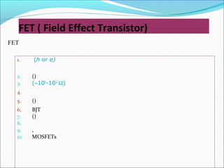
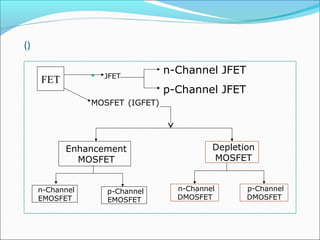
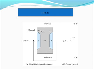
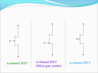
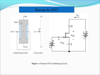
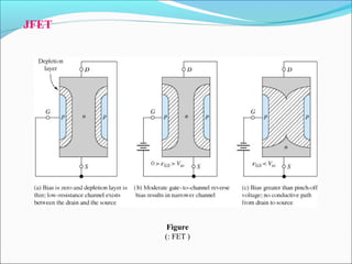
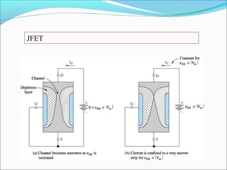
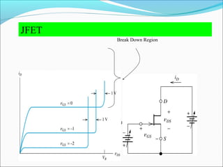
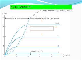
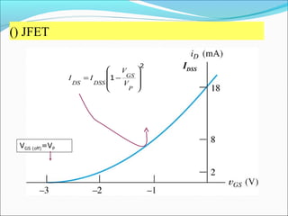
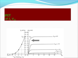


This document discusses field effect transistors (FETs), including JFETs and MOSFETs. It provides figures illustrating the structure and characteristics of an n-channel JFET, including its biasing circuit. The document also shows typical drain characteristics and transfer curves of a JFET.


![Aim-to study characterstics of fet (field effect [Autosaved].pptx](https://cdn.slidesharecdn.com/ss_thumbnails/aim-tostudycharactersticsoffetfieldeffectautosaved-221113041420-4dcee974-thumbnail.jpg?width=640&height=640&fit=bounds)