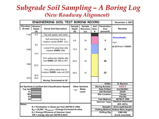
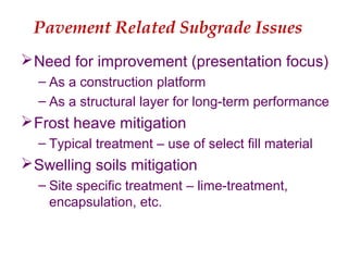
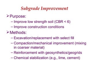
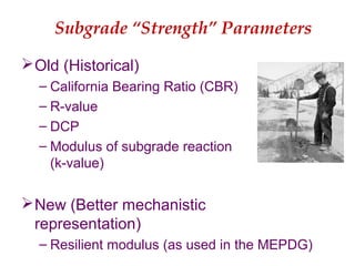
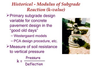
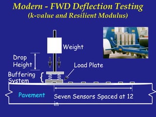
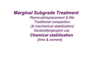
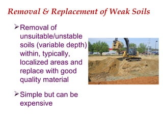
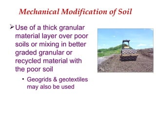
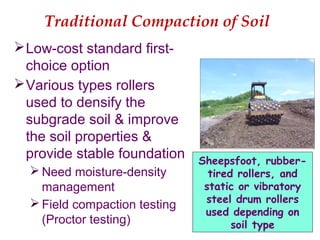
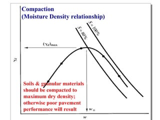
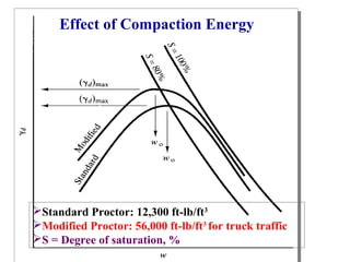
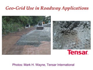
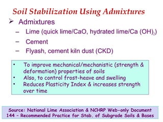
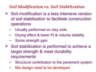
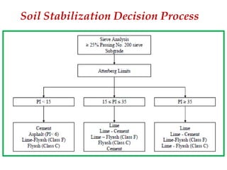
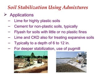
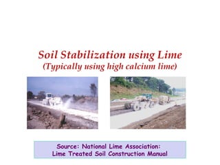
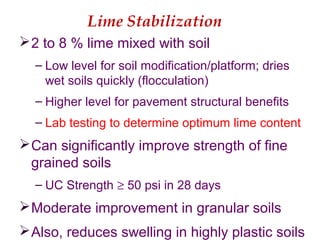
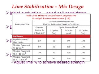
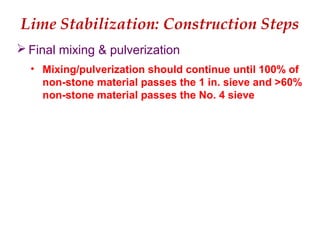
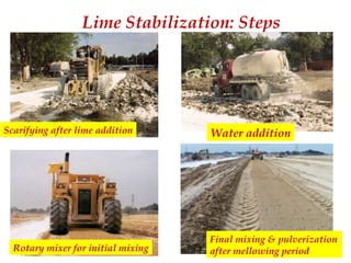
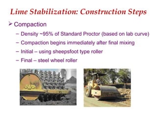
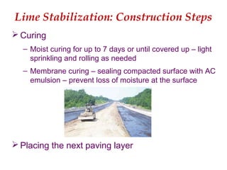
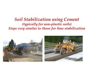
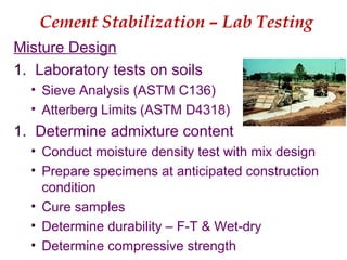
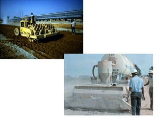
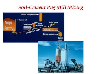
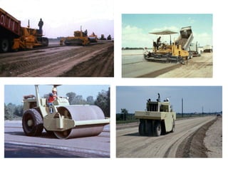
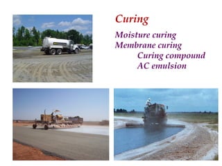
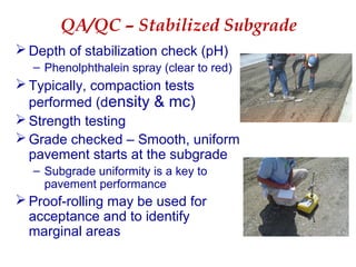
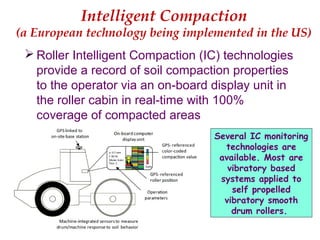
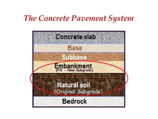
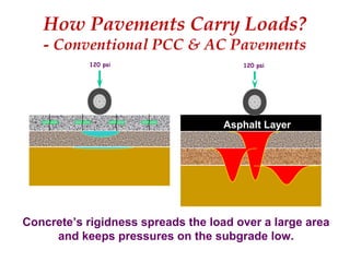
This document summarizes a presentation on subgrade stabilization methods for concrete pavements. It discusses the role of the subgrade in pavement performance and outlines various treatment options including removal and replacement, compaction, geotextiles, chemical stabilization using lime and cement. The presentation provides details on laboratory testing and construction steps for lime and cement stabilization, including mixing, compaction, curing and quality control. Subgrade stabilization improves the strength and uniformity of the subgrade for use as a construction platform and structural layer.

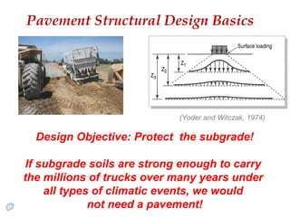
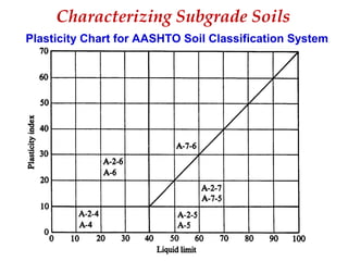
![Characterizing Subgrade Soils
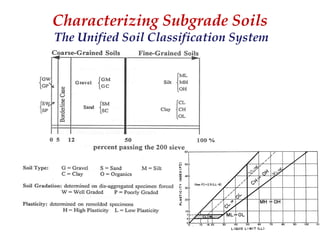
AASHTO Soil Classification System
Granular Soils w/ <35% passing
No. 200 (0.075 mm) sieve
Silt-Clay Soils w/ >35% passing
No. 200 (0.075 mm) sieve
A-1, A-2 &
A-3
A-4, A-5,
A-6, & A-7
GI = (F-35)[0.2+0.005(LL-40)] + 0.01(F-15)(PI-10)
where, GI = Group Index - follows symbol in ( ).
F = % < 0.075 mm](https://image.slidesharecdn.com/tayabji-160225025858/85/Subgrade-Stabilization-Materials-Methods-10-320.jpg)