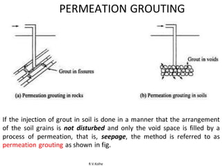
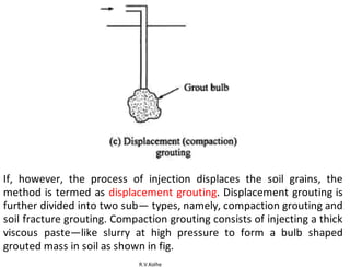
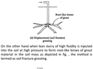
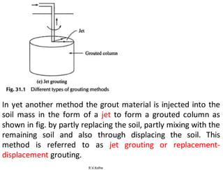
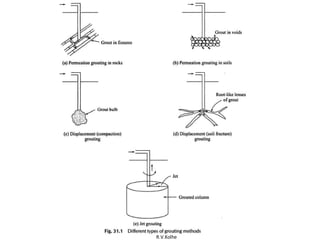
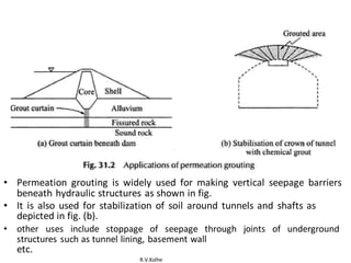
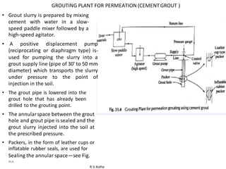
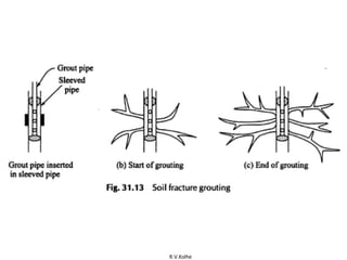
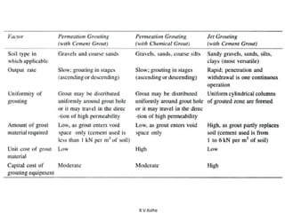
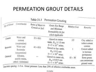
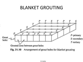
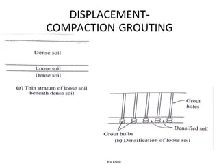
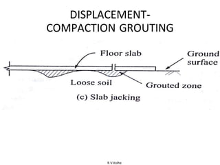
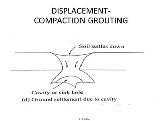
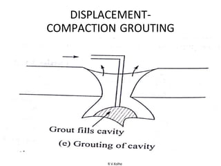
This document discusses different grouting methods. It describes permeation grouting where grout is injected to fill voids without disturbing soil grains. Displacement grouting displaces soil grains, including compaction grouting using thick grout to form bulb shapes, and soil fracture grouting using lean grout to form root-like lenses. Jet grouting forms grouted columns by partly replacing and mixing with soil. Permeation grouting is used to form seepage barriers and stabilize tunnels. Displacement-compaction grouting involves high pressure injection of a soil-cement grout mixture to form 0.5-1m bulbous intrusions.
The presentation illustrates a technique for ground improvement, Grouting. In India, grouting is still not being used very much. In this presentation, I have demonstrated the basic types of grouting, goals of ground improvement and two case studies of grouting.
Soil nailing is a technique used to reinforce and strengthen existing ground.Soil nailing consists of installing closely spaced bars into a slope or excavation as construction proceeds from top down.It is an effective and economical method of constructing retaining wall for excavation support, support of hill cuts, bridge abutments and high ways.This process is effective in cohesive soil, broken rock, shale or fixed face conditions.
This is about types of shear failure in soil, describe all the three types of the bearing capacity failure of soil.
This is prepared by (Abdullah Kawkas Galaly) a student in civil engineering department at Salahaddin University in Erbil-Kurdistan region.
In this presentation i have gone through about various prospects and challenges that have been faced at the time of installation,its types,method of installation &its application.
Loose granular sand deposits formed during the land reclamation process are vulnerable to
liquefaction upon imparting seismic forces. These loose granular sand fills could encounter
bearing failures or compress beyond tolerable limits under static and dynamic loads
Know the necessity of ground improvement
Understand the various ground improvement techniques available
Select design suitable ground improvement technique for existing soil conditions in the field
Dewatering is the removal of water from solid material or soil by wet classification, centrifugation , filtration, or similar solid-liquid separation processes, such as removal of residual liquid from a filter cake by a filter press as part of various industrial processes.
Dewatering is a term to describe the removal of groundwater or surface water from for example a construction site. In construction the water is pumped from wells or sumps to temporarily lower the groundwater levels, to allow excavation in dry and stable conditions below natural groundwater level.
There are mainly 2 types of foundation deep and shallow foundation.
under reamed pile foundation .
there are different types of foundation and underreamed pile foundation is a type of foundation which helps to increase the load bearing capacity of the soil.
there are different types of devices used for this construction such as spiral augers, boring guide , under reamer.
and the construction steps are shown in the slide , advantages and disadvantages etc.
and all the brief is given clearly in the slide .
For full course visit our website
https://www.machenlink.com/course/foundation-engineering/
Description
Wash boring is a fast and simple method for advancing holes in all types of soils.
Boulders and rock cannot be penetrated by this method.
The method consists in first driving a casing through which a hollow drill rod with a sharp chisel or chopping bit at the lower end is inserted.
Water is forced under pressure through the drill rod which is alternately raised and dropped and also rotated.
The resulting chopping and jetting action of the bit and water disintegrate the soil.
The cutting is forced up to the ground surface in the form of soil − water slurry through the annular space between the drill rod and the casing.
The change of soil stratification could be guessed from the rate of progress and the colour of wash water.
The samples recovered from the wash water are almost valueless for interpreting the correct geotechnical properties of soil.
For full course visit our website :
https://www.machenlink.com/course/foundation-engineering/
Follow #MachenLink
Facebook: https://www.facebook.com/machenLink/
Linkedin: https://www.linkedin.com/company/machenlink/
Twitter: https://twitter.com/MachenLink
this presentation describes in details the sinking operation of well foundations in different conditions and situations. the content here is suitable only for basic knowledge and educational purposes.
Saudi Arabia stands as a titan in the global energy landscape, renowned for its abundant oil and gas resources. It's the largest exporter of petroleum and holds some of the world's most significant reserves. Let's delve into the top 10 oil and gas projects shaping Saudi Arabia's energy future in 2024.
CFD Simulation of By-pass Flow in a HRSG module by R&R Consult.pptxR&R Consult
CFD analysis is incredibly effective at solving mysteries and improving the performance of complex systems!
Here's a great example: At a large natural gas-fired power plant, where they use waste heat to generate steam and energy, they were puzzled that their boiler wasn't producing as much steam as expected.
R&R and Tetra Engineering Group Inc. were asked to solve the issue with reduced steam production.
An inspection had shown that a significant amount of hot flue gas was bypassing the boiler tubes, where the heat was supposed to be transferred.
R&R Consult conducted a CFD analysis, which revealed that 6.3% of the flue gas was bypassing the boiler tubes without transferring heat. The analysis also showed that the flue gas was instead being directed along the sides of the boiler and between the modules that were supposed to capture the heat. This was the cause of the reduced performance.
Based on our results, Tetra Engineering installed covering plates to reduce the bypass flow. This improved the boiler's performance and increased electricity production.
It is always satisfying when we can help solve complex challenges like this. Do your systems also need a check-up or optimization? Give us a call!
Work done in cooperation with James Malloy and David Moelling from Tetra Engineering.
More examples of our work https://www.r-r-consult.dk/en/cases-en/
Final project report on grocery store management system..pdfKamal Acharya
In today’s fast-changing business environment, it’s extremely important to be able to respond to client needs in the most effective and timely manner. If your customers wish to see your business online and have instant access to your products or services.
Online Grocery Store is an e-commerce website, which retails various grocery products. This project allows viewing various products available enables registered users to purchase desired products instantly using Paytm, UPI payment processor (Instant Pay) and also can place order by using Cash on Delivery (Pay Later) option. This project provides an easy access to Administrators and Managers to view orders placed using Pay Later and Instant Pay options.
In order to develop an e-commerce website, a number of Technologies must be studied and understood. These include multi-tiered architecture, server and client-side scripting techniques, implementation technologies, programming language (such as PHP, HTML, CSS, JavaScript) and MySQL relational databases. This is a project with the objective to develop a basic website where a consumer is provided with a shopping cart website and also to know about the technologies used to develop such a website.
This document will discuss each of the underlying technologies to create and implement an e- commerce website.
Immunizing Image Classifiers Against Localized Adversary Attacksgerogepatton
This paper addresses the vulnerability of deep learning models, particularly convolutional neural networks
(CNN)s, to adversarial attacks and presents a proactive training technique designed to counter them. We
introduce a novel volumization algorithm, which transforms 2D images into 3D volumetric representations.
When combined with 3D convolution and deep curriculum learning optimization (CLO), itsignificantly improves
the immunity of models against localized universal attacks by up to 40%. We evaluate our proposed approach
using contemporary CNN architectures and the modified Canadian Institute for Advanced Research (CIFAR-10
and CIFAR-100) and ImageNet Large Scale Visual Recognition Challenge (ILSVRC12) datasets, showcasing
accuracy improvements over previous techniques. The results indicate that the combination of the volumetric
input and curriculum learning holds significant promise for mitigating adversarial attacks without necessitating
adversary training.
Industrial Training at Shahjalal Fertilizer Company Limited (SFCL)MdTanvirMahtab2
This presentation is about the working procedure of Shahjalal Fertilizer Company Limited (SFCL). A Govt. owned Company of Bangladesh Chemical Industries Corporation under Ministry of Industries.
2. R.V.Kolhe
Grouting
• INJECTION OF SLURRY/LIQUID SOLUTION INTO
ROCK OR SOIL.
• INJECTED MTRL IS GROUT
• TECHNIQUE DEVELOPED FOR MAKING VERTICAL
SEEPAGE BARRIER BY CEMENT SLURRY.
• CEMENTING CAPABILITY INCREASES SOIL/ROCK STR.
• CEMENT SLURRY IS NON-PERMEABLE SO
SPL CHEMICALS WERE INVENTED.
3. R.V.Kolhe
TYPE OF GROUTS
• SUSPENSIONS – CEMENT OR
BENTONITE GROUT
• EMULSIONS- BITUMEN EMULSIONS
• SOLUTIONS- SODIUM SILICATE
OR ACRYLIC RAISIN.
4. R.V.Kolhe
DESIRABLE CHAR OF GROUTS
• STABLITY: CAPABLITY OF GROUT TO
REMAIN IN FLUID STATE.
– GROUT NOT TO SEGREGATE BEFORE
REACHING DESTINATION.
– STABLITY OF CLAY CEMENT GROUT >
CEMENT GROUT
5. R.V.Kolhe
DESIRABLE CHAR OF GROUTS
• SETTING TIME : TIME TO SET TO
CEMENTED MASS OR GEL.
– EARLY SETTING : REACHING DESTINATION.
– LATE SETTING: GROUT WASHED AWAY. (SEEPAGE)
– RETARD OR ACCELERATE BY ADDITIVES
6. R.V.Kolhe
DESIRABLE CHAR OF GROUTS
• PERMANENCE: RESISTANCE OF GROUT AGAINST
DISPLACEMENT FROM SOIL WITH TIME.
– CEMENT GROUTS > BENTONITE GROUT ( WASHED
AWAY BY SEEPAGE WATER)
7. R.V.Kolhe
DESIRABLE CHAR OF GROUTS
• TOXICITY: CONTAMINATE SURROUNDING
SOIL AND GROUND WATER.
• HEALTH HAZARD
8. R.V.Kolhe
TYPES OF GROUTING TECHNIQUES
• GROUTING METHODS FOR SOILS ARE CLASSIFIED AS:
(I) PERMEATION GROUTING
(II) DISPLACEMENT-SOIL FRACTURE GROUTING
(III) DISPLACEMENT-COMPACTION GROUTING
(IV) JET OR REPLACEMENT-DISPLACEMENTGROUTING
9. R.V.Kolhe
PERMEATION GROUTING
If the injection of grout in soil is done in a manner that the arrangement
of the soil grains is not disturbed and only the void space is filled by a
process of permeation, that is, seepage, the method is referred to as
permeation grouting as shown in fig.
11. R.V.Kolhe
If, however, the process of injection displaces the soil grains, the
method is termed as displacement grouting. Displacement grouting is
further divided into two sub— types, namely, compaction grouting and
soil fracture grouting. Compaction grouting consists of injecting a thick
viscous paste—like slurry at high pressure to form a bulb shaped
grouted mass in soil as shown in fig.
12. R.V.Kolhe
On the other hand when lean slurry of high fluidity is injected
into the soil at high pressure to form root-like lenses of grout
material in the soil mass as depicted in fig. , the method is
termed as soil fracture grouting.
14. R.V.Kolhe
In yet another method the grout material is injected into the
soil mass in the form of a jet to form a grouted column as
shown in fig. by partly replacing the soil, partly mixing with the
remaining soil and also through displacing the soil. This
method is referred to as jet grouting or replacement-
displacement grouting.
17. R.V.Kolhe
Permeation Grouting
• CEMENT GROUTS, BENTENITE GROUTS AND
CHEMICAL GROUTS ARE USED FOR
PERMEATION GROUTING AS SUMMARIZED
1N TABLE.
• CHEMLCAL GROUTS ARE SUITABLE FOR THE
MAXIMUM RANGE OF GRAIN SIZES BUT THEY
ARE VERY EXPENSIVE
18. R.V.Kolhe
PERMEATION GROUTING
• Cement grout not only fills the voids and reduces
permeability but also sets with time and binds
the soil grains together. As a consequence, the
strength of the soil mass increases and its
compressibility decreases. Sometimes cement in
grout is replaced by clay to reduce cost. solved
• When the objective of grouting is only to reduce
permeability, bentonite grouts can be used.
However, the permanence of such grouts under
high hydraulic gradients is questionable and
often cement is added.
19. R.V.Kolhe
• Permeation grouting is widely used for making vertical seepage barriers
beneath hydraulic structures as shown in fig.
• It is also used for stabilization of soil around tunnels and shafts as
depicted in fig. (b).
• other uses include stoppage of seepage through joints of underground
structures such as tunnel lining, basement wall
etc.
20. R.V.Kolhe
GROUTING PLANT FOR PERMEATION (CEMENTGROUT )
• Grout slurry is prepared by mixing
cement with water in a slow-
speed paddle mixer followed by a
high-speed agitator.
• A positive displacement pump
(reciprocating or diaphragm type) is-
used for pumping the slurry into a
grout supply line (pipe of 30' to 50 mm
diameter) which transports the slurry
under pressure to the point of
injection in the soil.
• The grout pipe is lowered into the
grout hole that has already been
drilled to the grouting point.
• The annularspace between the grout
hole and grout pipe is sealed and the
grout slurry injected into the soil at
the prescribed pressure.
• Packers, in the form of leather cups or
inflatable rubber seals, are used for
Sealing the annular space—see Fig.
31,4,
21. R.V.Kolhe
• when the grouting has to
be executed down to the
shallow depth below the
ground surface (few
meters.
• Grout hole is drilled
completely.
• grout pipe is inserted
from top
• annular spaces are sealed
and grouting is done
under low pressure
26. R.V.Kolhe
Descending and Ascending Stage
Grouting:
• For grouting to larger depths, grouting is executed in stages.
• In the DESCENDING STAGE grouting, drilling and grouting
are executed alternatively in stages of 3 to 5 m in the
downward direction as shown in Fig.
• For each stage, as one goes deeper, one can use higher
grout pressure.
• ASCENDING STAGE grouting shown in Fig. is executed in a
reverse manner
• The grout hole is drilled to the full depth in one operation.
• Subsequently the grout pipe is lowered to the deepest segment
of the hole and the annular space sealed using a packer.
• Grouting is carried out at high pressure. Thereafter, the grout
pipe and the packer is raised in stagesof3 to 5 m and the
29. R.V.Kolhe
Descending and Ascending Stage
Grouting:
• ASCENDING STAGE GROUTING HAS THE ADVANTAGE
THAT THE DRILLING IS ALL DONE IN ONE GO.
• IN DESCENDING STAGE GROUTING, ONE CAN
USE HIGHER GROUT PRESSURES AS ONE MOVES
TO LOWER STAGES
• NOT ONLY BECAUSE OF GREATER DEPTH BUT ALSO
BECAUSE THE UPPER LEVELS HAVE BEEN GROUTED
AND THE SOIL FORMATION IS MORE FIRM ESPECIALLY
WHEN GROUTS USED ARE OF TYPES THAT SET AND
ADD TO STRENGTH.
30. R.V.Kolhe
GROUTING USING SLEEVED PIPE
• ASCENDING STAGE GROUTING IN SOIL MAY BE HAMPERED
DUE TO IMPROPER FUNCTIONING OF PACKERS WHEN PUSHED
OR EXPANDED AGAINST AN UNEVEN GROUT HOLE WALL.
• HENCE SLEEVED PIPE GROUTING DEPICTED IN FIG. 31.8 IS
OFTEN MORE SUCCESSFUL. IN THIS A SLOTTED PIPE,
HAVING VERTICAL SLOTS COVERED WITH THIN RUBBER
SLEEVES, IS LOWERED INTO THE GROUT HOLE.
• THE SPACE BETWEEN THE SLOTTED PIPE AND THE GROUT HOLE
IS SEALED WITH CEMENT-BENTONITE SEAL.
• GROUTING IS DONE BY LOWERING THE GROUT PIPE WITH A
PAIR OF PACKERS TO THE DESIRED ELEVATION INSIDE THE
SLOTTED PIPE AND INJECTING THE GROUT UNDER PRESSURE.
• GROUT PRESSURE BRUSTS THE TEMP RUBBER SLEEVE AND
CEMENT BENTONITE SEAL.
• GROUT PERMEATES INTP ADJOINING SOIL.
35. R.V.Kolhe
CURTAIN GROUTING
• GROUTING ARRANGEMENTS THAT PERMEATION GROUTING
IS OFTEN USED FOR MAKING VERTICAL SEEPAGE BARRIERS
BENEATH HYDRAULIC STRUCTURES HAS ALREADY BEEN
HIGHLIGHTED EARLIER.
• THIS GROUTING ARRANGEMENT IS CALLED CURTAIN
GROUTING. TYPICALLY, GROUTING IS CARRIED OUT TO THE
REQUIRED DEPTH ALONG 2 TO 3 ROWS OF GROUT HOLES.
• THE GROUT HOLES IN EACH ROW MAY BE SPACED AT 2 TO 4
M AND STAGGERED IN PLAN ALONG THE ROWS.
• GROUTING IS FIRST DONE IN PRIMARY HOLES SPACED 15—
25 M APART FOLLOWED BY SECONDARY HOLES AT
INTERMEDIATE LOC AND THEN TERTIARY HOLES AT 2—4 M
SPACING AS SHOWN IN FIG. 31.9.
37. R.V.Kolhe
BLANKET GROUTING
• IT REFERS PERMEATION GROUTING CARRIED OUT
OVER A LARGE AREA IN PLAN DOWN TO A SHALLOW
FIXED DEPTH.
• SUCH A GROUTED ZONE IN THE SHAPE OF A BLANKET
IS OFTEN CREATED BEHIND HYDRAULIC STRUCTURE
TO REDUCE WATER LOSS BY SEEPAGE FROM THE
RESERVOIR,
• THE GROUTED BLANKET INCREASES THE SEEPAGE PATH.
• GROUTING IS FIRST EXECUTED IN PRIMARY HOLES AT
A GRID SPACING OF ABOUT 20 M FOLLOWED BY
SECONDARY HOLES AT A GRID SPACEING OF ABOUT
38. R.V.Kolhe
10 M AND FINALLY IN A CLOSELY SPACED TERTIARY
GRID OF HOLES AT A SPACING OF ABOUT 5 M.
40. R.V.Kolhe
DISPLACEMENT-COMPACTION
GROUTING
• INJECTION OF GROUT UNDER HIGH PRESSURE IN SOIL MASS.
• CAUSES DISPLACEMENT OF SOIL PARTICLES.
• BULBOUS/SPHERICAL SHAPED INTRUSIONS RANGE OF 0.5 TO 1.0
M ARE FORMED.
• THE GROUT MATERIAL USED IS A MIXTURE OF SOIL AND CEMENT,
SEE TABLE 31.2.
•
• THE SOIL USED IN THE GROUT HAS SUFFICIENT SAND SIZED
PARTICLES TO DEVELOP INTERNAL FRICTION AS WELL AS ENOUGH
FINE GRAINED PARTICLES TO PROVIDE PLASTICITY TO THE GROUT.
41. R.V.Kolhe
DISPLACEMENT-COMPACTION
GROUTING
• WATER IS ADDED TO YIELD A PASTE-LIKE CONSISTENCY
OF THE GROUT.
• WE NEED TO USE JUST ENOUGH CEMENT SO THAT THE
ENGINEERING PROPERTIES OF THE GROUTED MASS ARE
SIMILAR TO OR BETTER THAN THOSE OF THE NATURAL SOIL
IN A COMPACTEDSTATE.
• IN SOME CASES, WHEN PERMANENCE IS NOT AN ISSUE,
CEMENT NEED NOT BE USED AT ALL AND THE GROUT CAN
BE JUST A SOIL SLURRY.
43. R.V.Kolhe
DISPLACEMENT-COMPACTION
GROUTING
• THE TECHNOLOGY OF INJECTION OF GROUT IS SIMILAR TO THAT FOR
PERMEATIONGROUTING.
• HOWEVER, SINCE THE GROUT MIX IS MUCH STIFFER THAN IN PERMEATION
GROUTING AND GROUT PRESSURES ARE MUCH HIGHER, THE GROUT PUMPS USED
ARE HEAVY-DUTY CONCRETE PUMPS.
• GROUT PIPE DIAMETERS RANGE FROM 50 TO 75 MM.
• THE QUANTITY OF GROUT INJECTED IS OBSERVED TO RANGE FROM 3 TO
12 PERCENT BY VOLUME OF THE TREATED LOOSE SOIL,
• DISPLACEMENT-COMPACTIONGROUTING IS SUITABLE FOR ALL TYPES OF LOOSE
COARSE GRAINED SOILS, SOFT FINE GRAINED SOILS WHICH ARE NOT
SATURATED AND FOR FILLING UNDERGROUND CAVITIES.
• IT IS NOT USED IN SOFT SATURATED FINE GRAINED SOILS BECAUSE GROUTING
RAISES THE PORE WATER PRESSURE IN THE SOIL MASS LEADING TO UNEVEN
AND AGGRAVATED SETTLEMENT PROBLEMS.
44. R.V.Kolhe
DISPLACEMENT-COMPACTION
GROUTING
• IN COMPARISON TO OTHER TYPES OF GROUTING,
DISPLACEMENT— COMPACTION GROUTING IS OBSERVED TO BE
USEFUL FOR THE FOLLOWING SITUATIONS:
• (I) DENSIFICATION OF THIN LOOSE STRATUM UNDERLYING DENSE
SOIL AND LOCATED AT CONSIDERABLE DEPTH—SEE FIG. 31.11(A) AND
(B)
• (II) DENSIFICATION OF POCKETS OF LOOSE SOILS BENEATH
FOUNDATIONS OR FLOOR SLABS THAT ARE REVEALED AFTER
CONSTRUCTION IS COMPLETED INCLUDING LEVELING OF SUNKEN
FLOORS—ALSO REFERRED TO AS SLAB-JACKING OR BACK-
PACKING— SEE FIG. 31.11(C),
45. R.V.Kolhe
DISPLACEMENT-COMPACTION
GROUTING
• (III) FILLING OF LARGE UNDERGROUND CAVITIES CAUSED BY BROKEN
UNDERGROUND UTILITY LINES, BY PIPING/ EROSION, OR BY
DISSOLUTION AS DEPICTED IN FIG. 31.11(D) AND (E); IN SUCH CASES,
THE CAVITIES ARE FIRST FILLED WITH GROUT AND THEN THE
DENSITY OF SURROUNDING SOIL IS INCREASED BY GROUTING WITH
APPROPRIATE GROUT PRESSURE, AND
• (IV) DENSIFICATION OF SOILS SHOWING ORGANIC
DEGRADATION WITH TIME. DISPLACEMENT-COMPACTION
GROUTING IS MOST OFTEN USED IN SMALL AREAS OR POCKETS
AS A REMEDIATION TECHNIQUE. IT IS RARELY COST EFFECTIVE
FOR GROUND IMPROVEMENT OVER LARGE AREAS.
50. R.V.Kolhe
Displacement—Soil Fracture Grouting
• SOIL FRACTURE GROUTING TECHNIQUE IS A
DISPLACEMENT GROUTING TECHNIQUE IN WHICH A
LEAN SLURRY OF CEMENT, SOIL AND WATER IS
INJECTED INTO THE SOIL AT HIGH PRESSURE TO
FRACTURE THE SOIL AND FORM ROOT—LIKE OR THIN
LENS SHAPED ZONES OF GROUT MATERIAL IN THE
SOIL MASS.
• THE GROUT MATERIAL SPREADS ALL AROUND THE
GROUT HOLE CAUSING DENSIFICATION OF THE
SOIL MASS AND AN INCREASE IN ITS
MACROSCOPIC STRENGTH.
•
52. R.V.Kolhe
SUCH GROUTING ALSO CAUSES THE GROUND TO
HEAVE AND THAT CAN BE USED TO ADVANTAGE,
FOR EXAMPLE, IN RECTIFYING TILT IN BUILDINGS
AND RESTORING THEIR VERTICALITY AS SHOWN IN
FIG. 31.12.
53. R.V.Kolhe
Restoration of verticality of a tilted
building
• RESTORATION OF VERTICALITY OF A TILTED
BUILDING SUCH GROUTING IS USUALLY
ACCOMPLISHED USING THE SLEEVED PIPE
GROUTING TECHNIQUE AS DEPICTED IN FIG. 31.13.
• GROUT HOLES, 100 MM IN DIAMETER, ARE DRILLED
AT REGULAR INTERVALS AND SLEEVED PIPES WITH
MULTIPLE SLOTS ARE PLACED IN THE GROUT HOLES.
GROUTING IS DONE IN SEGMENTS OF 0.3 TO 1.0 M
ALONG THE LENGTH OF EACH SLOTTED PIPE USING
GROUT PRESSURES AS HIGH AS 4000 KN/MZ.
55. R.V.Kolhe
Jet or Replacement—Displacement
Grouting
• GROUTING IN THIS TECHNIQUE, A SPECIAL GROUT PIPE CALLED
THE MONITOR HAVING HIGH-SPEED JETS OF WATER OR GROUT IS
USED TO ERODE AND EXCAVATE THE SOIL
• THEREAFTER, AS THE MONITOR IS WITHDRAWN, STRONG,
IMPERVIOUS COLUMNS ARE PRODUCED BY MIXING GROUT
WITH THE REMAINING SOIL.
• THE TECHNIQUE IS CALLED REPLACEMENT DISPLACEMENT BECAUSE
A PART OF THE SOIL IS REMOVED BY THE JETTING ACTION AND IS
REPLACED BY THE GROUT MATERIAL AND BECAUSE THE GROUT IS
INJECTED AT HIGH PRESSURE PARTLY TO MIX WITH THE REMAINING
SOIL AND BARTLY TO DISPLACE THE SURROUNDING SOIL.
56. R.V.Kolhe
Jet or Replacement—Displacement
Grouting
• THE GROUT MATERIALS USED ARE CEMENT AND WATER WITH
SOME ADDITIVE AS INDICATED IN TABLE 31.3.
• JET GROUTING IS THE YOUNGEST OF GROUTING TECHNIQUES
AND CONSULTING GEOTECHNICAL ENGINEERS HAVE BEGUN TO
USE IT AFTER THE MID-1980S.
• IT IS MORE EXPENSIVE THAN PERMEATION GROUTING, DUE TO
LARGER CONSUMPTION OF CEMENT PER UNIT VOLUME OF
SOIL MASS TREATED.
57. R.V.Kolhe
• NEVERTHELESS, IT IS NOW EXTENSIVELY USED AS IT PRODUCES
MORE UNIFORM GROUTING, CAN BE USED IN MOST SOILS AND HAS
A HIGHER RATE OF PRODUCTIVITY
59. R.V.Kolhe
Jet or Replacement—Displacement
Grouting
• TYPES OF JET GROUTING
– SINGLE JET OR ONE FLUID SYSTEM
– DOUBLE JET OR 02 FLUID SYSTEM
– TRIPLE JET OR 03 FLUID SYSTEM.
• THE FIRST STEP IS TO DRILL A GROUT HOLE OF 100 TO 150 MM DIAMETER.
• THE HOLE IS KEPT STABLE BY USING WATER CIRCULATION OR BENTONITE
SLURRY CIRCULATION.
• IN THE SECOND STEP, JETTING COMMENCES IN THE HORIZONTALDIRECTION
THROUGH NOZZLES (2 TO 4 MM IN DIAMETER)AT THE TIP OF THE MONITOR
THAT IS ROTATED AT 5 TO 30 REVOLUTIONS PER MINUTE.
• THE SOIL CUTTINGS TRAVEL TO THE GROUND SURFACE THROUGH THE
ANNULAR SPACE BETWEEN THE BOREHOLEAND THE MONITOR.
• THE MONITOR IS LIFTED AT A RATE OF 50 TO 300 MM PER MINUTE IN THE
THIRD STEP RESULTING IN THE FORMATLON OF A GROUTED COLUMN.
61. R.V.Kolhe
• IN THE SINGLE JET SYSTEM, A HORIZONTAL JET OF GROUT AS
SHOWN IN FIG. SIMULTANEOUSLY ERODES THE SOIL AND
MIXES WITH A PART OF THE REMAINING SOIL TO FORM A
GROUTED COLUMN.
• IN THE DOUBLE JET SYSTEM, THE EROSIVE EFFECT OF THE GROUT
JET IS CONSIDERABLY ENHANCED BY THE ADDITION OF A SHROUD
OF COMPRESSED AIR
• THE TRIPLE JET SYSTEM USES A WATER JET SHROUDED BY AIR TO
ERODE THE SOIL AND A SEPARATE NOZZLE BENEATH THE WATER
JET TO PLACE THE GROUT AS DEPICTED IN FIG. 31.15(C).
62. R.V.Kolhe
GROUTED COLUMNS -DIAMETER
• JET GROUTED COLUMNS CAN BE FORMED IN ALMOST ALL TYPES OF
SOILS RANGING FROM SANDY GRAVELS TO CLAYS.
• SANDS ARE BEST SUITED FOR TREATMENT YIELDING THE LARGEST DIAMETER
OF COLUMNS.
• PRESENCE OF INTERPARTICLEATTRACTIVE FORCES REDUCES THE
EROSIVE EFFICIENCY OF THE JETS.
• HENCE DIAMETERSOF GROUTED COLUMNS ARE PROGRESSIVELY SMALLER
IN SANDY SILTS, SILTS, CLAYEY SILTS AND CLAYS.
• GRAVELS DO NOT RESPOND WELL TO JET GROUTING BOTH BECAUSE OF LOSS OF
WATER OR GROUT THROUGH ITS VOIDS AND THE DIFFICULTY IN REMOVING
GRAVEL PARTICLES VIA THE ANNULAR SPACE BETWEEN THE GROUTHOLE AND
THE MONITOR.
• SANDY GRAVEL CAN BE TREATED BY JET GROUTING.
• JET GROUTED COLUMN DIAMETERS IN SANDS, SILTY SANDS AND CLAYEY SILTS
ARE TYPICALLY OF THE ORDER OF
– 1.0, 0.85 AND 0.5 M RESPECTIVELY FOR SINGLE JET SYSTEM AND
– 2.0, 1.5 AND 1.0 M RESPECTIVELY FOR TRIPLE JETSYSTEM.
63. R.V.Kolhe
THE TRIPLE JET SYSTEM IS THE MOST EFFECTIVE IN REMOVING SOIL
AND GIVES THE LARGEST DIAMETER OF GROUTED COLUMNS
AMONGST THE THREE SYSTEMS. IN EACH SYSTEM, THE DIAMETER OF
THE GROUTED COLUMN CAN BE VARIED BY CHANGING THE RATE OF
WITHDRAWAL OF THE MONITOR. FIG. SHOWS THE COMPONENTS OF
EQUIPMENT FOR TRIPLE JET GROUTING.
64. R.V.Kolhe
ROWS OF GROUTED
COLUMNS AS SHOWN
IN FIG. ARE USED
BENEATH DAMS TO
FORM SEEPAGE
BARRIERS WITH
COEFFICIENT OF
PERMEABILITY IN THE
RANGE OF 10
-7
TO 10
-9
M/SEC.