The document presents an overview of soil stabilization techniques using cement and lime, detailing construction methods, advantages, and disadvantages of each technique. It includes a case study on the in-situ stabilization of a road base in Malaysia, highlighting design parameters, compressive strength results, and empirical relationships derived from field tests. The findings indicate significant improvements in structural capacity and provide insights for monitoring the performance of stabilized layers.


![Age
at
test (days)
In-situ compressive strength (MPa)
from core samples
In-situ compressive
strength (MPa) from
cube specimens
1 - 3
3 - 5.5
4 4.5 -
7 - 6.0
8 6.0 -
29 7.5 -
Table : Compressive strength of the CTB layer
[Source: G. W. K. Chai et al (2005)]](https://image.slidesharecdn.com/soilcementshort-190403110130/75/Overview-of-Soil-Stabilization-Cement-Lime-PPT-14-2048.jpg)
![Falling Weight Deflectometer (FWD) was adopted to determine the in-situ stiffness of the
cement stabilized road base material.
Figure : Falling weight deflectometer (FWD)
[Source: researchgate.net]](https://image.slidesharecdn.com/soilcementshort-190403110130/75/Overview-of-Soil-Stabilization-Cement-Lime-PPT-15-2048.jpg)
![• Normalized deflection readings were measured by geophones at distances (0, 300mm,
600mm, 900mm, 1200mm, 1500mm and 2100mm) from the center of the loading
plate
• FWD test:
Center deflection reading of 900 microns at 85 percentile value.
For tests performed on the CTB, center deflection value at 85 percentiles for the 3
and 7 days are 500 micron and 400 microns, respectively.
Center deflection at 85 percentile gives a value of 300 micron for 28 days cure.
Figure : FWD center deflection profiles before and after cement stabilization
A: (3 and 7 days); B: (28 days)
[Source: G. W. K. Chai et al (2005)]](https://image.slidesharecdn.com/soilcementshort-190403110130/75/Overview-of-Soil-Stabilization-Cement-Lime-PPT-16-2048.jpg)
![Test stages Effective stiffness modulus (MPa)
at 85 percentile values
Pavement Layers CTB Road base
Granular Road base
Before Recycling
- 280
CTB after 3 days 700 -
CTB after 7 days 1150 -
Asphalt Surface after
28 days
1350 -
Table : Effective stiffness modulus of the CTB layer
[Source: G. W. K. Chai et al (2005)]](https://image.slidesharecdn.com/soilcementshort-190403110130/75/Overview-of-Soil-Stabilization-Cement-Lime-PPT-17-2048.jpg)
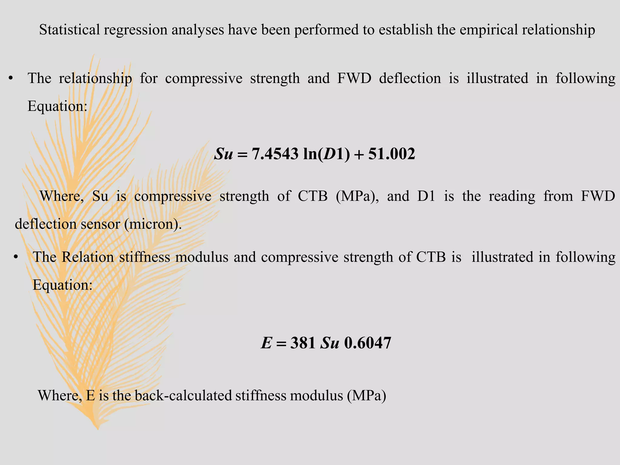
![Figure : Compressive strength and deflection D1 relationship from FWD.
[Source: G. W. K. Chai et al (2005)]](https://image.slidesharecdn.com/soilcementshort-190403110130/75/Overview-of-Soil-Stabilization-Cement-Lime-PPT-18-2048.jpg)
![Figure : Stiffness modulus and compressive strength relationship from field test
[Source: G. W. K. Chai et al (2005)]](https://image.slidesharecdn.com/soilcementshort-190403110130/75/Overview-of-Soil-Stabilization-Cement-Lime-PPT-19-2048.jpg)