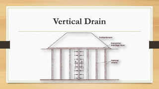
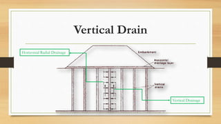
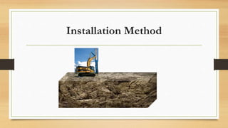
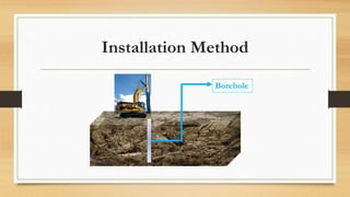
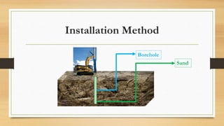
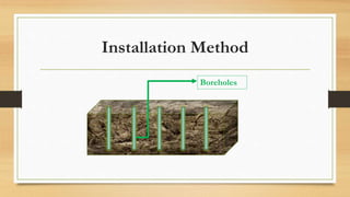
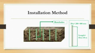
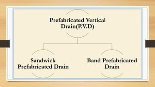
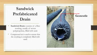
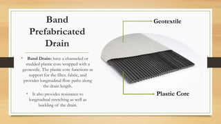
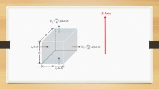
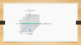
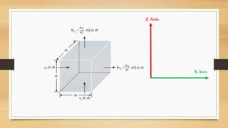
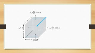
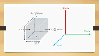
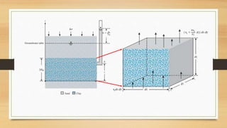
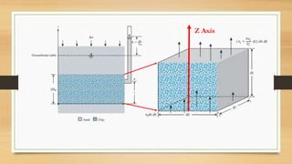
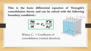
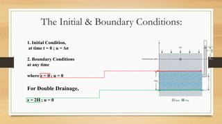
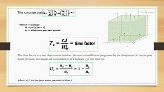
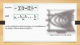
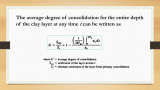
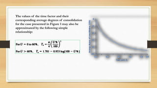
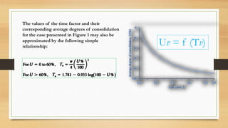
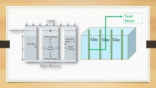
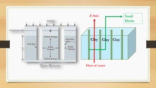
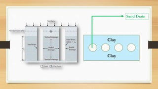
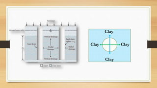
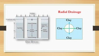
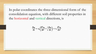
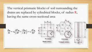
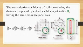
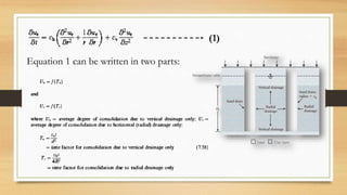
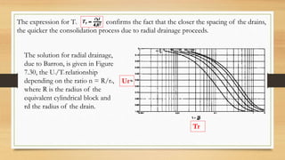
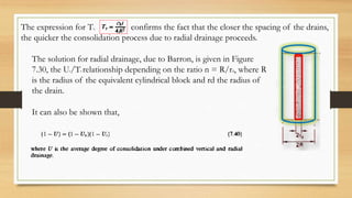
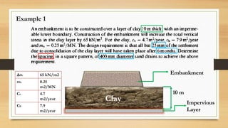
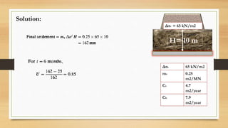
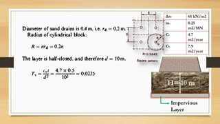
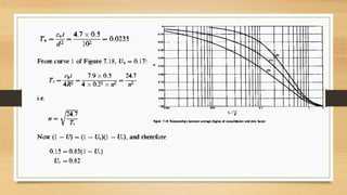
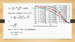
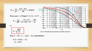
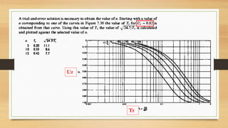
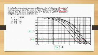
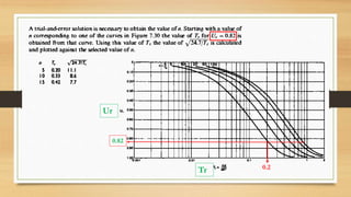
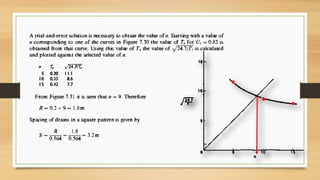
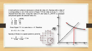
Vertical Drain
By
Sanchari Halder
Contents
• Introduction
• Installation Method
• Prefabricated Vertical Drain(P.V.D)
• Design Consideration
• Mathematical Example
Vertical Drain
The slow rate of consolidation in saturated clays of
low permeability may be accelerated by means of
vertical drains which shorten the drainage path
within the clay.
Vertical Drain
Vertical Drain
Horizontal Radial Drainage
Vertical Drainage
Installation Method
Installation Method
Installation Method
Borehole
Installation Method
Borehole
Sand
Installation Method
Borehole
Sand
Installation Method
Borehole
Sand
Installation Method
Boreholes
Installation Method
Boreholes
Dia= 200~400 mm
Length=
Over 30 m
Prefabricated Vertical Drain(P.V.D)
•Prefabricated drains are now generally
used and tend to be more economic
than backfilled drains for a given area
of treatment
Prefabricated Vertical
Drain(P.V.D)
Sandwick
Prefabricated Drain
Band Prefabricated
Drain
Sandwick
Prefabricated
Drain
• Sandwick Drains consists of a filter
stocking, usually of woven
polypropylene, filled with sand.
• Compressed air is used to ensure that
the stocking is completely filled with
sand.
Geotextile
Band
Prefabricated
Drain
• Band Drains have a channeled or
studded plastic core wrapped with a
geotextile. The plastic core functions as
support for the filter. fabric, and
provides longitudinal flow paths along
the drain length.
• It also provides resistance to
longitudinal stretching as well as
buckling of the drain.
Geotextile
Plastic Core
Design Consideration
• The rate of soil consolidation or settlement is
controlled by how rapidly the pore water can
escape from the soil
• The controlling variables are the spacing between
the drains and the permeability of the soil.
Design Consideration
• By developing a set of design curves of drain
spacing, fill height, and consolidation time, the
most economical drain spacing and height of fill
can be selected to achieve a given degree of
consolidation in a specified time period.
Vertical Drain
Spacing
Drains are
normally installed
in either a square
or a triangular
pattern.
Vertical Drain
Spacing
Drains are
normally installed
in either a square
or a triangular
pattern.
Z Axis
Z Axis
X Axis
Z Axis
X Axis
Y Axis
Z Axis
This is the basic differential equation of Terzaghi’s
consolidation theory and can be solved with the following
boundary conditions :
Where, Cv = Coefficient of
consolidation (vertical direction)
1. Initial Condition,
at time t = 0 ; u = Δσ
2. Boundary Conditions
at any time
where z = 0 ; u = 0
For Double Drainage,
z = 2H ; u = 0
The Initial & Boundary Conditions:
The solution yields,
The time factor is a non dimensional number. Because consolidation progresses by the dissipation of excess pore
water pressure, the degree of consolidation at a distance z at any time t is
where, uz= excess pore water pressure at time t.
Equation
and
can be combined to obtain the degree of consolidation at
any depth z. This is shown in Figure 1.
Figure1: Variation of Uz with
The average degree of consolidation for the entire depth
of the clay layer at any time t can be written as
The values of the time factor and their
corresponding average degrees of consolidation
for the case presented in Figure 1 may also be
approximated by the following simple
relationship:
The values of the time factor and their
corresponding average degrees of consolidation
for the case presented in Figure 1 may also be
approximated by the following simple
relationship: Uv = f (Tv)
Sand
Drain
Clay Clay Clay
Sand
Drain
Clay Clay Clay
Z Axis
Flow of water
Sand Drain
Clay
Clay
Clay
Clay
Clay
Clay
Clay
Clay
Radial Drainage
Clay
Clay
Design Consideration
• It is essential for a successful design that the
coefficients of consolidation in both the horizontal
and the vertical directions (ch and cv, respectively)
are known as accurately as possible. In particular,
the accuracy of ch is the most crucial factor in
design.
In polar coordinates the three-dimensional form of the
consolidation equation, with different soil properties in
the horizontal and vertical directions, is
The vertical prismatic blocks of soil surrounding the
drains are replaced by cylindrical blocks, of radius R,
having the same cross-sectional area
The vertical prismatic blocks of soil surrounding the
drains are replaced by cylindrical blocks, of radius R,
having the same cross-sectional area
c c
cc
c c
Equation 1 can be written in two parts:
(1)
Tr
Ur
The expression for Tr, confirms the fact that the closer the spacing of the drains,
the quicker the consolidation process due to radial drainage proceeds.
The solution for radial drainage,
due to Barron, is given in Figure
7.30, the Ur/Tr relationship
depending on the ratio n = R/rd,
where R is the radius of the
equivalent cylindrical block and
rd the radius of the drain.
The expression for Tr, confirms the fact that the closer the spacing of the drains,
the quicker the consolidation process due to radial drainage proceeds.
The solution for radial drainage, due to Barron, is given in Figure
7.30, the Ur/Tr relationship depending on the ratio n = R/rd, where R
is the radius of the equivalent cylindrical block and rd the radius of
the drain.
It can also be shown that,
Example 1
Embankment
10 m
Clay Impervious
Layer
Δσv 65 kN/m2
mv 0.25
m2/MN
Cv 4.7
m2/year
Ch 7.9
m2/year
Solution:
H= 10 m
Δσv 65 kN/m2
mv 0.25
m2/MN
Cv 4.7
m2/year
Ch 7.9
m2/year
Δσv = 65 kN/m2
H= 10 m
Δσv 65 kN/m2
mv 0.25
m2/MN
Cv 4.7
m2/year
Ch 7.9
m2/year
Impervious
Layer
1
0.17
1
0.17
Tr
Ur
Tr
Ur
0.82
Tr
Ur
0.82
0.2
Reference
• Craig, R. F. (2004), “Craig’s Soil Mechanics”, Spon Press, 29 West 35th Street, New York,
USA, 7th Edition, pp. 268~274.
• Das, B. M. (2009), “Principles of Geotechnical Engineering”, Cengage Learning, Stamford,
USA, 7th Edition, pp. 294~364.
Thank you!
Email: sanchari.halder@yahoo.com

Vertical Drain