Download as PDF, PPTX


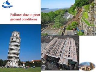
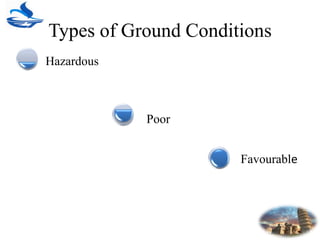
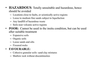
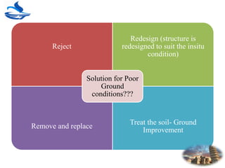
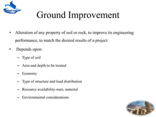
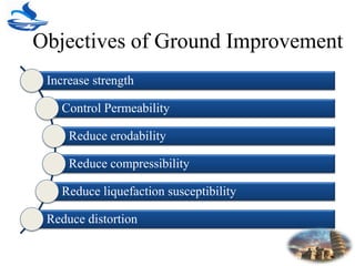
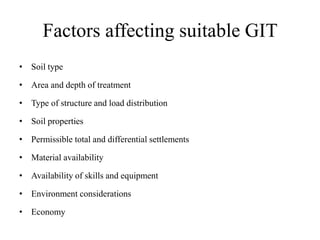
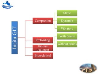
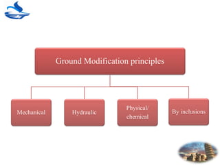
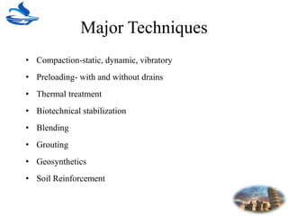
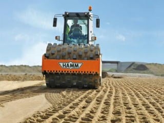
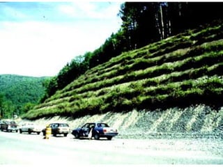
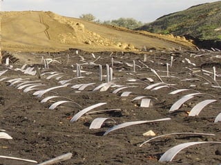
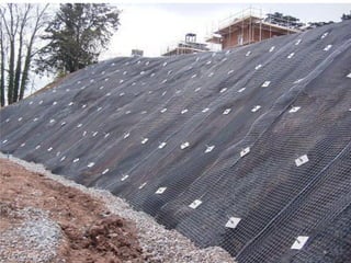
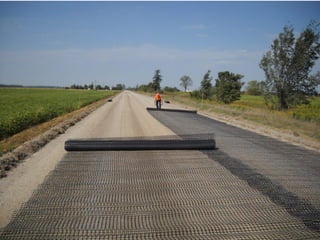
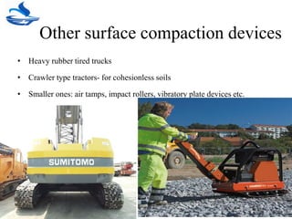
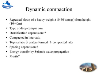
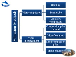
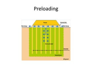
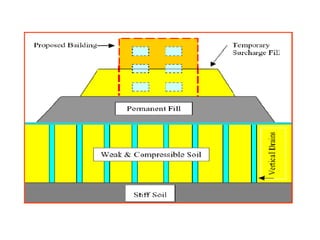
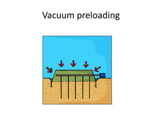
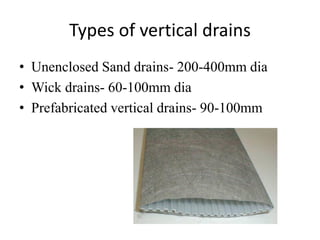
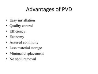
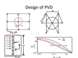
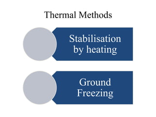
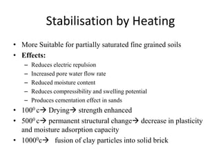
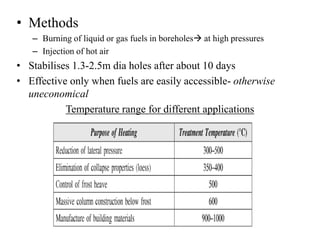
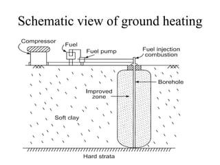
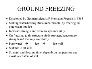


This document discusses various ground improvement techniques used to treat poor ground conditions. It begins by classifying ground conditions as hazardous, poor, or favorable. Poor ground conditions that cannot be used in their insitu state but can be treated include expansive soils, organic soils, loose sands and silts, and fissured rocks. The document then discusses various ground improvement techniques including compaction methods, preloading, grouting, geosynthetics, soil reinforcement, stone columns, and thermal methods. It provides details on techniques like dynamic compaction, vibrocompaction, vibrodisplacement, prefabricated vertical drains, and compaction piles. The objectives, principles, factors affecting selection, and design of various techniques are


