Downloaded 12 times


This document discusses various digital encoding and modulation techniques used for transmitting digital and analog data over transmission channels. It describes: - Digital signaling, where digital data is encoded into a digital signal using techniques like NRZ-L, NRZI, etc. to minimize bandwidth and errors. - Analog signaling, where analog or digital data modulates an analog carrier signal using techniques like ASK, FSK, PSK to transmit over analog lines. - Specific digital modulation techniques like BPSK, QPSK, MFSK that encode digital data onto signal properties like phase, frequency or amplitude to maximize bandwidth efficiency and minimize errors. - How analog modulation techniques like AM, FM, PM encode analog data onto an
Overview of pass band transmission and key encoding/modulation techniques.
Comparison between digital and analog signaling, highlighting modulation methods and encoding examples.
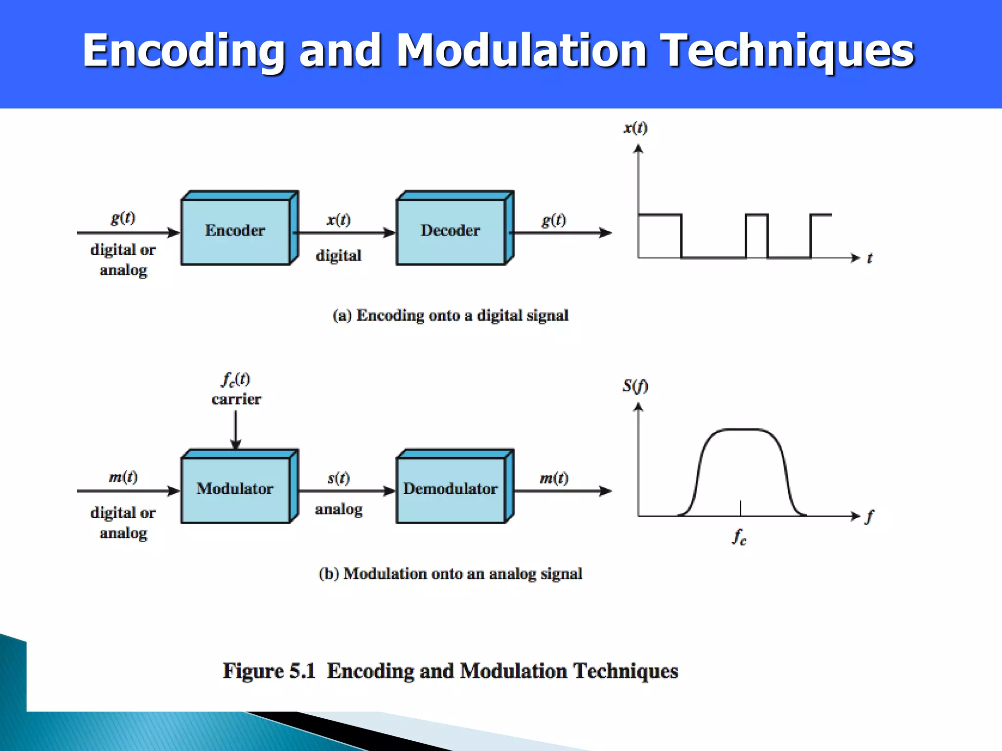
Explanation of digital signals, data rates, and modulation rates including signal elements.
Factors impacting signal interpretation such as timing, signal levels, SNR, and bandwidth.
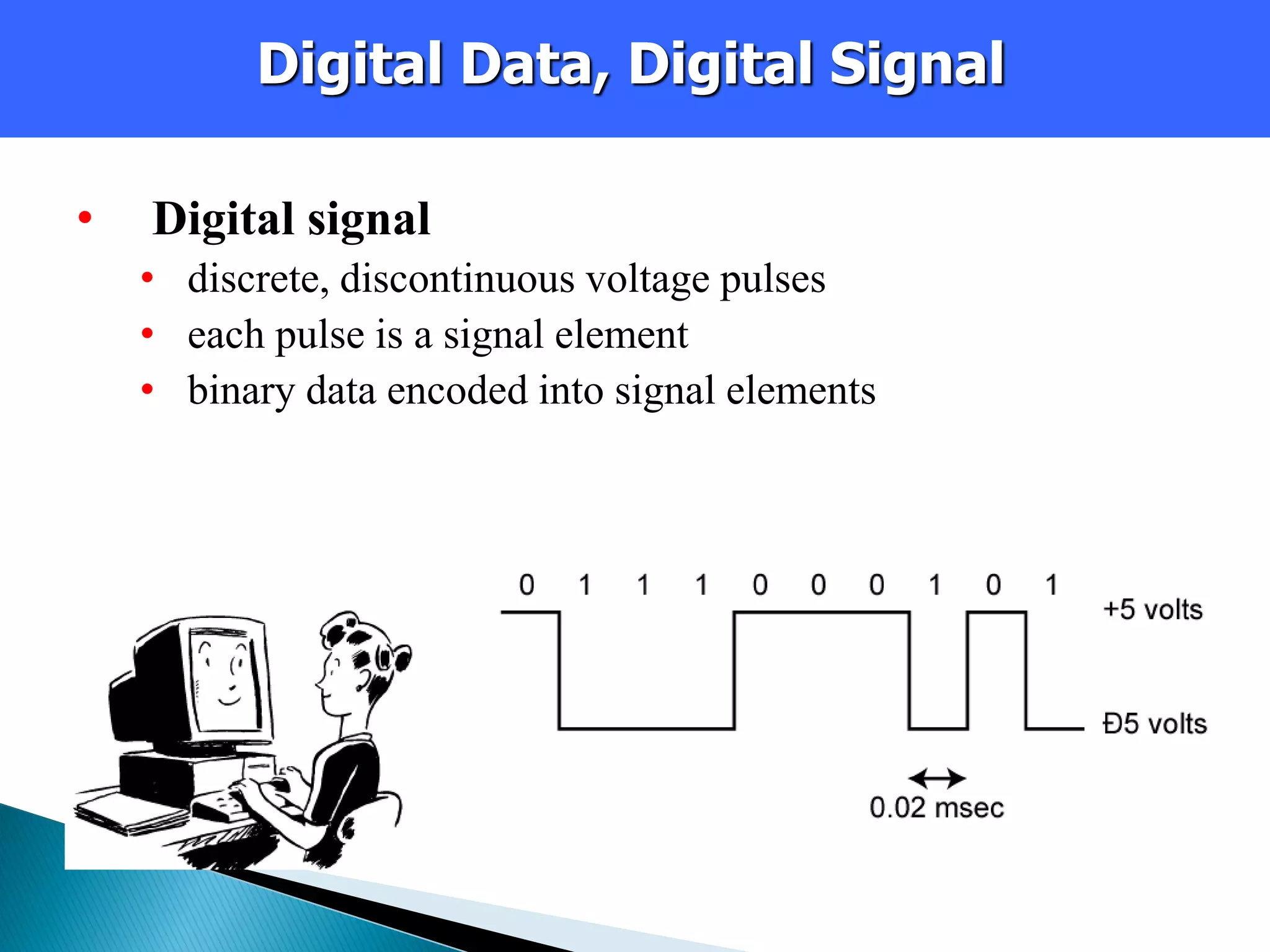
Introduction to various modulation techniques like ASK and their Susceptibility to noise.
Details on BFSK and MFSK, including their efficiency and use in various applications.
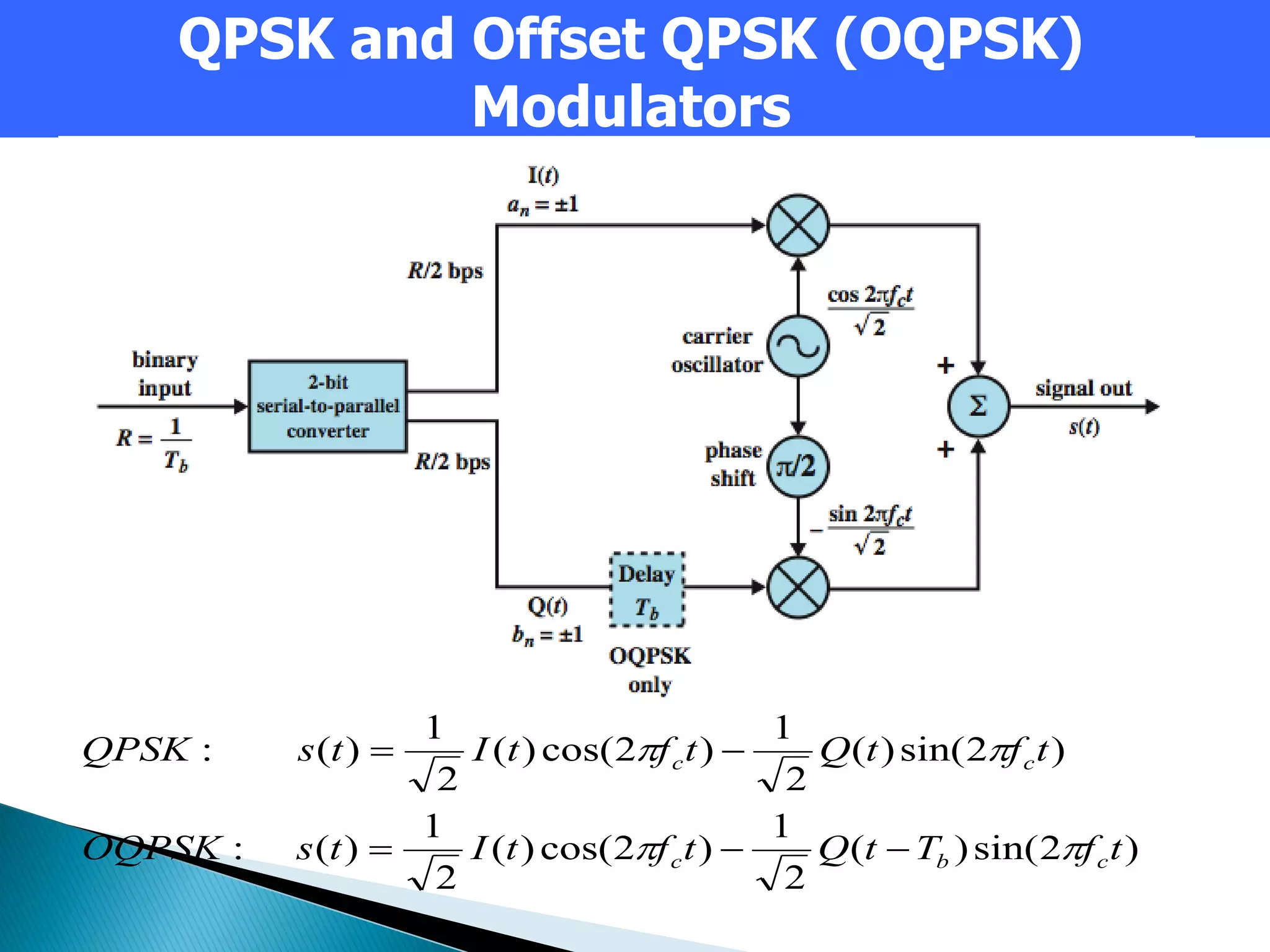
Descriptions of PSK, DPSK, and QPSK, emphasizing their phase shift representations.
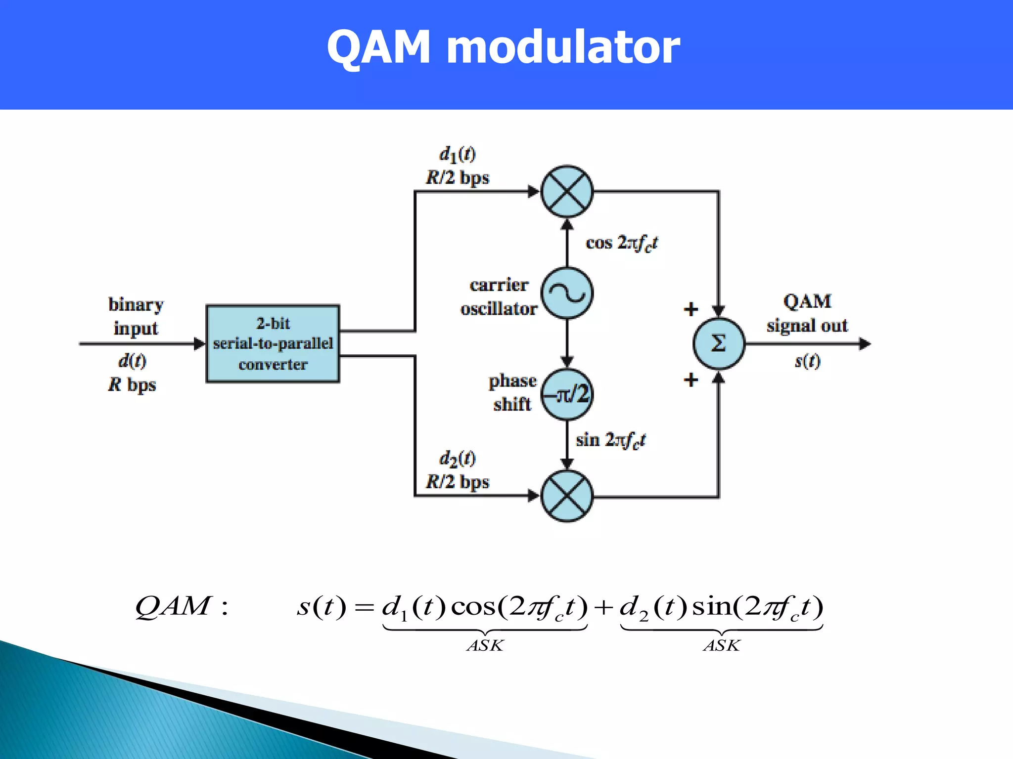
Evaluates bandwidth efficiency and bit error rates of ASK, FSK, PSK, and QAM.Introduction to QAM, its variants, and applications in modern communication systems.