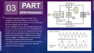
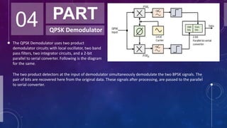
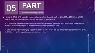
Quadrature Phase Shift Keying (QPSK) is a digital modulation scheme that transmits two bits of information at a time, effectively doubling the data rate compared to Binary Phase Shift Keying (BPSK) while requiring half the bandwidth. QPSK uses four distinct phase shifts to encode data, making it more efficient and robust for various wireless communication standards like GSM, CDMA, and LTE. The document discusses the modulation and demodulation process, technical implementation using MATLAB, and concludes by highlighting QPSK's advantages over BPSK in data transmission.

![06 PART
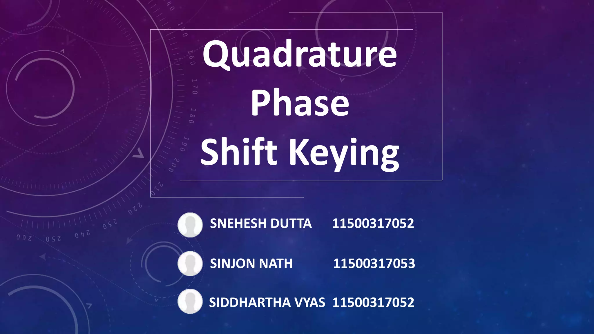
MATLAB Code for QPSK
Modulation and Demodulation
clc;
clear all;
close all;
data=[0 1 0 1 1 1 0 0 1 1]; % information
%Number_of_bit=1024;
%data=randint(Number_of_bit,1);
figure(1)
stem(data, 'linewidth',3), grid on;
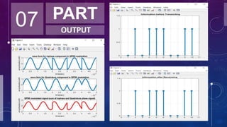
title(' Information before Transmiting ');
axis([ 0 11 0 1.5]);
data_NZR=2*data-1; % Data Represented at NZR form for QPSK modulation
s_p_data=reshape(data_NZR,2,length(data)/2); % S/P convertion of data
br=10.^6; %Let us transmission bit rate 1000000
f=br; % minimum carrier frequency
T=1/br; % bit duration
t=T/99:T/99:T; % Time vector for one bit information
% XXXXXXXXXXXXXXXXXXXXXXX QPSK modulation XXXXXXXXXXXXXXXXXXXXXXXXXXXXXXXXX](https://image.slidesharecdn.com/quadraturephaseshiftkeying-200324143423/85/Quadrature-phase-shift-keying-8-320.jpg)
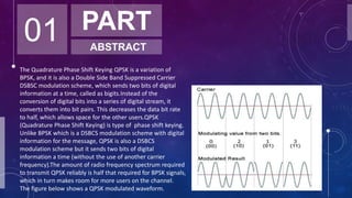
![y=[];
y_in=[];
y_qd=[];
for(i=1:length(data)/2)
y1=s_p_data(1,i)*cos(2*pi*f*t); % inphase component
y2=s_p_data(2,i)*sin(2*pi*f*t) ;% Quadrature component
y_in=[y_in y1]; % inphase signal vector
y_qd=[y_qd y2]; %quadrature signal vector
y=[y y1+y2]; % modulated signal vector
end
Tx_sig=y; % transmitting signal after modulation
tt=T/99:T/99:(T*length(data))/2;
figure(2)
subplot(3,1,1);
plot(tt,y_in,'linewidth',3), grid on;
title(' wave form for inphase component in QPSK modulation ');
xlabel('time(sec)');
ylabel(' amplitude(volt0');
subplot(3,1,2);
plot(tt,y_qd,'linewidth',3), grid on;
title(' wave form for Quadrature component in QPSK modulation ');
xlabel('time(sec)');](https://image.slidesharecdn.com/quadraturephaseshiftkeying-200324143423/85/Quadrature-phase-shift-keying-9-320.jpg)
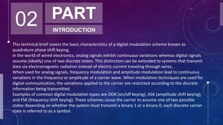
![ylabel(' amplitude(volt0');
subplot(3,1,3);
plot(tt,Tx_sig,'r','linewidth',3), grid on;
title('QPSK modulated signal (sum of inphase and Quadrature phase signal)');
xlabel('time(sec)');
ylabel(' amplitude(volt0');
% XXXXXXXXXXXXXXXXXXXXXXXXXXXX QPSK demodulation XXXXXXXXXXXXXXXXXXXXXXXXXX
Rx_data=[];
Rx_sig=Tx_sig; % Received signal
for(i=1:1:length(data)/2)
%%XXXXXX inphase coherent dector XXXXXXX
Z_in=Rx_sig((i-1)*length(t)+1:i*length(t)).*cos(2*pi*f*t);
% above line indicat multiplication of received & inphase carred signal
Z_in_intg=(trapz(t,Z_in))*(2/T);% integration using trapizodial rull
if(Z_in_intg>0) % Decession Maker
Rx_in_data=1;
else
Rx_in_data=0;
end](https://image.slidesharecdn.com/quadraturephaseshiftkeying-200324143423/85/Quadrature-phase-shift-keying-10-320.jpg)
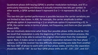
![%%XXXXXX Quadrature coherent dector XXXXXX
Z_qd=Rx_sig((i-1)*length(t)+1:i*length(t)).*sin(2*pi*f*t);
%above line indicat multiplication ofreceived & Quadphase carred signal
Z_qd_intg=(trapz(t,Z_qd))*(2/T);%integration using trapizodial rull
if (Z_qd_intg>0)% Decession Maker
Rx_qd_data=1;
else
Rx_qd_data=0;
end
Rx_data=[Rx_data Rx_in_data Rx_qd_data]; % Received Data vector
end
figure(3)
stem(Rx_data,'linewidth',3)
title('Information after Receiveing ');
axis([ 0 11 0 1.5]), grid on;](https://image.slidesharecdn.com/quadraturephaseshiftkeying-200324143423/85/Quadrature-phase-shift-keying-11-320.jpg)


![[Deck] What's New in Spark-Iceberg Integration via DSV2.pptx](https://cdn.slidesharecdn.com/ss_thumbnails/deckwhatsnewinspark-icebergintegrationviadsv2-260210005337-25955b12-thumbnail.jpg?width=640&height=640&fit=bounds)


