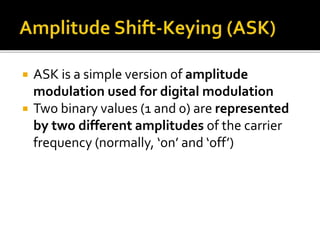
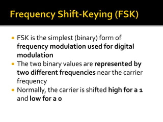
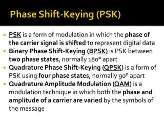
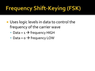
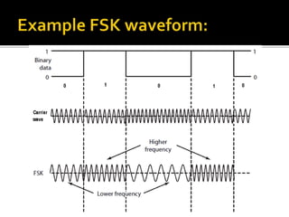
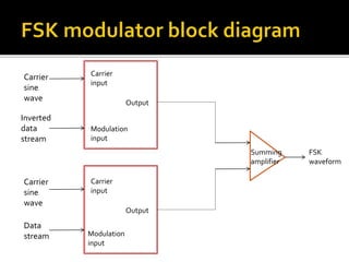
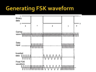
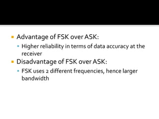
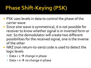
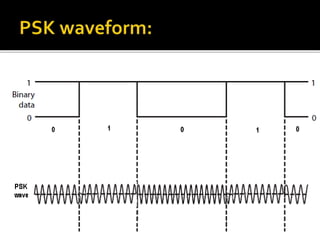
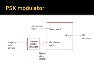
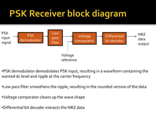
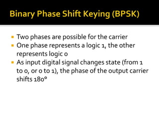
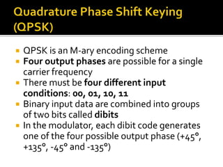
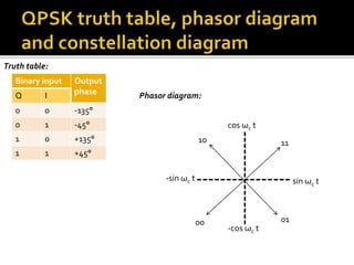
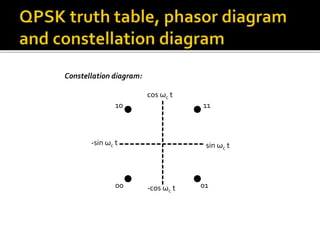
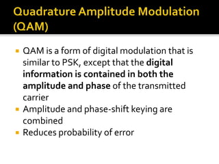
Study on Air-Water & Water-Water Heat Exchange in a Finned Tube Exchanger
Digital communication methods
1.
2. ASK is a simple version of amplitude
modulation used for digital modulation
Two binary values (1 and 0) are represented
by two different amplitudes of the carrier
frequency (normally, ‘on’ and ‘off’)
3. FSK is the simplest (binary) form of
frequency modulation used for digital
modulation
The two binary values are represented by
two different frequencies near the carrier
frequency
Normally, the carrier is shifted high for a 1
and low for a 0
4. PSK is a form of modulation in which the phase of
the carrier signal is shifted to represent digital data
Binary Phase Shift-Keying (BPSK) is PSK between
two phase states, normally 180° apart
Quadrature Phase Shift-Keying (QPSK) is a form of
PSK using four phase states, normally 90° apart
Quadrature Amplitude Modulation (QAM) is a
modulation technique in which both the phase and
amplitude of a carrier are varied by the symbols of
the message
5. M represents a digit that corresponds to the no.
of conditions, levels or combinations possible for
a given no. of binary variables
For example, an M-ary system with M=4 is a
digital signal with four possible conditions
No. of bits necessary to produce a given no. of
conditions is
N M 2 log
Where N = no. of bits
M = no. of conditions/levels/combinations
6. No. of conditions possible:
For example,
M N 2
With one bit, only 21 = 2 conditions possible
With two bits, 22 = 4 conditions possible
With three bits, 23 = 8 conditions possible
and so on…
7. Uses logic levels in the data to control the
amplitude of the carrier wave
Data = 1 Amplitude HIGH (switch ON)
Data = 0 Amplitude LOW (switch OFF)
ASK modulator block diagram:
Carrier input
Modulation
input
Output
Carrier sine
wave
Data
stream
ASK
waveform
8.
9. Rectifier Low pass
filter
Voltage
comparator
Voltage
reference
Binary
data
ASK
waveform
10. Rectifier
Rectifies the input ASK waveform to contain only
positive signal
However, signal still contains unwanted carrier wave
components, and waveform is too rounded and of
unreliable amplitudes
Low pass filter
Remove remnants of carrier wave
Voltage comparator
Signal passes through a voltage level to output a true
copy of the original data stream
11. Uses logic levels in data to control the
frequency of the carrier wave
Data = 1 frequency HIGH
Data = 0 frequency LOW
12.
13. There are many ways to generate an FSK
waveform. One way is to treat it as
combining two different ASK waves
14. Carrier
input
Modulation
input
Carrier
input
Modulation
input
Output
Output
Carrier
sine
wave
Inverted
data
stream
Carrier
sine
wave
Data
stream
Summing
amplifier
FSK
waveform
15.
16. Advantage of FSK over ASK:
Higher reliability in terms of data accuracy at the
receiver
Disadvantage of FSK over ASK:
FSK uses 2 different frequencies, hence larger
bandwidth
17. PSK uses levels in data to control the phase of the
carrier wave
Since sine wave is symmetrical, it is not possible for
receiver to know whether signal is in inverted form or
not. So the demodulator will create two different
possibilities for the received signal, one is the inverse
of the other
NRZ (non return-to-zero) code is used to detect the
logic levels
Data = 1 change in phase
Data = 0 no change in phase
18.
19. Carrier input
Modulation
input
Output
Carrier sine
wave
Bipolar
data
stream
PSK
waveform
Unipolar-bipolar
converter
Unipolar
data
stream
20. PSK
demodulator
Low
pass
filter
Voltage
comparator
PSK
input
signal
Differential
bit decoder
NRZ
data
output
Voltage
reference
•PSK demodulator demodulates PSK input, resulting in a waveform containing the
wanted dc level and ripple at the carrier frequency
•Low pass filter smoothens the ripple, resulting in the rounded version of the data
•Voltage comparator cleans up the wave shape
•Differential bit decoder extracts the NRZ data
21. Two phases are possible for the carrier
One phase represents a logic 1, the other
represents logic 0
As input digital signal changes state (from 1
to 0, or 0 to 1), the phase of the output carrier
shifts 180°
22. Truth table: (+90°)
Binary input Output phase
Logic 0 180°
Logic 1 0°
cos ωc t
(-90°)
-cos ωc t
(0°)
sin ωc t
Logic 1
(180°)
-sin ωc t
Logic 0
180°
Logic 0
0°
Logic 1
cos ωc t
-cos ωc t
Phasor diagram:
Constellation diagram:
23. QPSK is an M-ary encoding scheme
Four output phases are possible for a single
carrier frequency
There must be four different input
conditions: 00, 01, 10, 11
Binary input data are combined into groups
of two bits called dibits
In the modulator, each dibit code generates
one of the four possible output phase (+45°,
+135°, -45° and -135°)
24. Truth table:
Binary input Output
Q I phase
0 0 -135°
0 1 -45°
1 0 +135°
1 1 +45°
cos ωc t
-sin ωc t sin ωc t
-cos ωc t
Phasor diagram:
10
00
11
01
25. cos ωc t
sin ωc -sin ωc t t
-cos ωc t
10
00
11
01
Constellation diagram:
26. QAM is a form of digital modulation that is
similar to PSK, except that the digital
information is contained in both the
amplitude and phase of the transmitted
carrier
Amplitude and phase-shift keying are
combined
Reduces probability of error
27. For example, 8-QAM is an M-ary coding technique
where M = 8
The phasor diagram for 8-QAM is shown below:
cos ωc t
-sin ωc t sin ωc t
-cos ωc t
101
000
011
100 110
111
001
010
28. Constellation diagram for 8-QAM:
cos ωc t
-sin ωc t sin ωc t
-cos ωc t
101
000
011
100 110
111
001
010