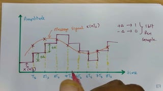
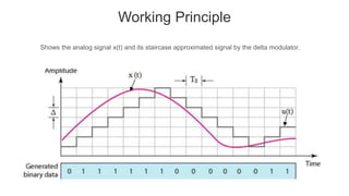
Delta modulation is a modulation technique that transmits only one bit per sample of an analog signal. It works by comparing the present sample value to the previous one and transmitting a bit to indicate if the value increased or decreased. This results in a stepped approximation of the original signal. Only a single bit is needed per sample, allowing delta modulation to have a lower signaling rate and bandwidth than PCM. However, it suffers from slope overload distortion if the input signal changes too quickly for the fixed step size. It also produces granular noise for small input variations due to the large step size. Despite these issues, delta modulation is used for voice transmission systems due to its simple implementation and emphasis on timely delivery over quality.


![Mathematical Expressions
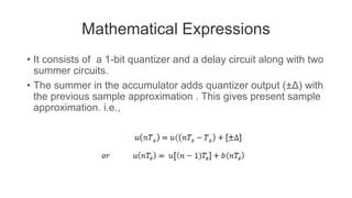
• The previous sample approximation u[(n-1)Ts ] is restored by
delaying one sample period Ts .
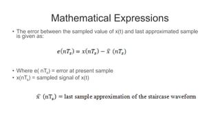
• The samples input signal x(nTs ) and staircase approximated
signal xˆ(nTs ) are subtracted to get error signal e(nTs ).
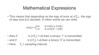
• Thus, depending on the sign of e(nTs ), one bit quantizer
generates an output of +Δ or -Δ .
• If the step size is +Δ, then binary ‘1’ is transmitted and if it is -Δ,
then binary ‘0’ is transmitted .](https://image.slidesharecdn.com/deltamodulation-201205110107/85/Delta-modulation-11-320.jpg)