Downloaded 1,666 times


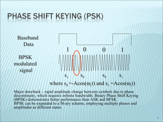
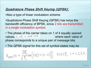
![Carrier: A sin[ωt +ϕ]
A = const
ω = const
ϕ = const
Amplitude modulation (AM)
A = A(t) – carries information
ω = const
ϕ = const
Frequency modulation (FM)
A = const
ω = ω(t)– carries information
ϕ = const
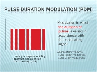
Phase modulation (PM)
A = const
ω = const
ϕ = ϕ(t) – carries information
2](https://image.slidesharecdn.com/digitalmodulation-140808063321-phpapp02/85/Digital-modulation-2-320.jpg)


The document discusses various modulation techniques, including Amplitude Modulation (AM), Frequency Modulation (FM), and Phase Modulation (PM), as well as different digital modulation schemes such as Binary Phase Shift Keying (BPSK), Differential Phase Shift Keying (DPSK), and Quadrature Phase Shift Keying (QPSK). It elaborates on the characteristics and performance of these techniques, including their efficiency in terms of bandwidth and power, and the impact of noise on signal integrity. Additionally, it covers m-ary modulation methods that extend these concepts by transmitting multiple bits per symbol, resulting in improved spectral efficiency.