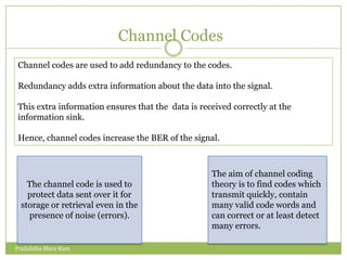


![Maximum –Likelihood decoding:
Viterbi algorithm [Step 1]
Pratishtha Shira Ram](https://image.slidesharecdn.com/convolutioncodes-13323403361394-phpapp02-120321093228-phpapp02/85/Convolution-Codes-19-320.jpg)
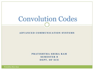
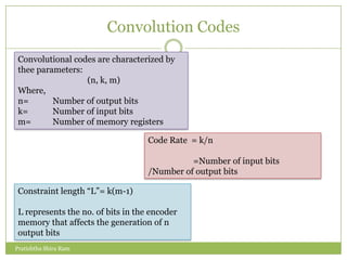
![Maximum –Likelihood decoding:
Viterbi algorithm [Step 2]
Pratishtha Shira Ram](https://image.slidesharecdn.com/convolutioncodes-13323403361394-phpapp02-120321093228-phpapp02/85/Convolution-Codes-20-320.jpg)
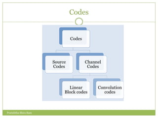
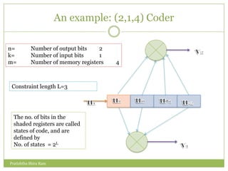
![Maximum –Likelihood decoding:
Viterbi algorithm [Step 3]
Pratishtha Shira Ram](https://image.slidesharecdn.com/convolutioncodes-13323403361394-phpapp02-120321093228-phpapp02/85/Convolution-Codes-21-320.jpg)
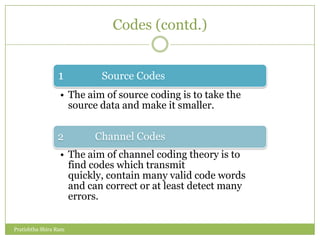
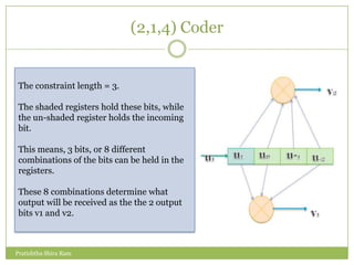
![Maximum –Likelihood decoding:
Viterbi algorithm [Step 4]
Pratishtha Shira Ram](https://image.slidesharecdn.com/convolutioncodes-13323403361394-phpapp02-120321093228-phpapp02/85/Convolution-Codes-22-320.jpg)


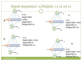
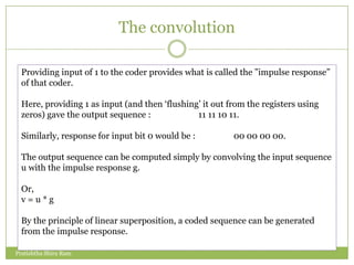
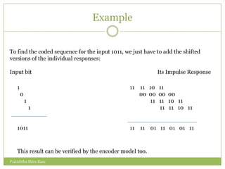
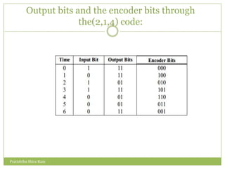
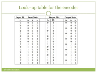
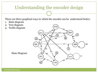
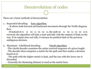
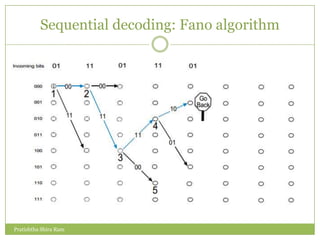
The document discusses convolution codes. It defines convolution codes as having three parameters (n, k, m) where n is the number of output bits, k is the number of input bits, and m is the number of memory registers. Convolutional codes add redundancy to protect data sent over noisy channels and are characterized by their constraint length L, which represents the number of bits in the encoder memory affecting output. The document provides an example of a (2,1,4) convolutional code and illustrates its operation through input sequences, state diagrams, tree diagrams, and trellis diagrams. It also describes methods for decoding convolution codes including sequential decoding using the Fano algorithm and maximum likelihood decoding using the Viterbi algorithm.