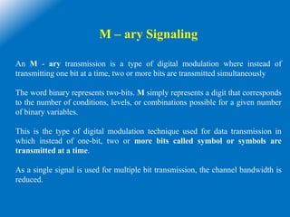
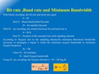
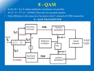
This document discusses M-ary digital modulation techniques. It begins by defining M-ary signaling as a technique where multiple bits are transmitted simultaneously using a single signal, instead of transmitting one bit at a time. It then provides the basic equation for calculating the number of possible conditions (M) based on the number of bits (N).
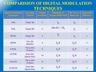
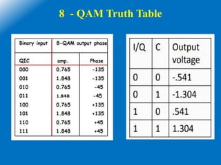
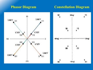
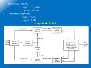
The document goes on to describe several common M-ary modulation techniques including M-ary PSK, M-ary QAM, and their basic principles and equations. It provides examples of 4-PSK, 8-PSK, 16-PSK, 8-QAM and 16-QAM, explaining their modulation/demodulation, constellations, and minimum bandwidth requirements. Finally, it compares several


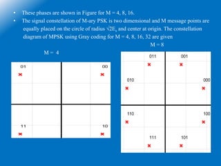


![8 – PSK Output Phase and Amplitude
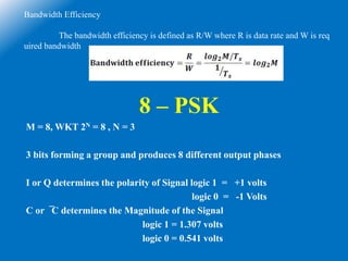
Bandwidth
The Output of the Balanced Modulator
= (V Sinωat)(Sinωct)
Where V = ± 1.307 or ± 0.541
ωat = 2Πfat = 2Πfbt and ωct = 2Πfct
fa = Fundamental frequency = (fb/3)/2 = fb/6
= (V Sin 2Π(fb/6)t)(Sin2Πfct)
= V[1/2(Cos(fc-fb/6) - Cos(fc+fb/6))]
Here (fc + fb/6) – (fc - fb/6) = BW
Band Width = fb/6 + fb/6 = fb/3](https://image.slidesharecdn.com/unit3-marysignaling-200830191642/85/EC-8395-Communication-Engineering-Unit-3-m-ary-signaling-19-320.jpg)
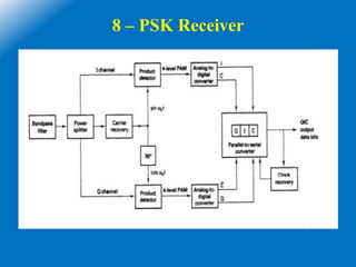


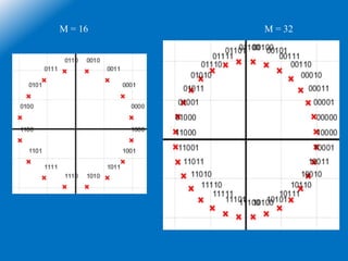
![Output of balanced modulator can be expressed as
= Sinωat x Sinωct
=
where fa = (fb/3)/2 = fb/6
The output frequency spectrum range is from fc-fa to fc+fa
The minimum bandwidth or Nyquist bandwidth
B = (fc+fb/6)-(fc-fb/6)
B = fb/3
Bit rate at I or Q or C channel is = fb/3
The highest fundamental frequency fa = fb/2 (Generally)
= (fb/3)/2
= fb/6
]t)ff(2[Cos
2
1
]t)ff(2[Cos
2
1
acac ](https://image.slidesharecdn.com/unit3-marysignaling-200830191642/85/EC-8395-Communication-Engineering-Unit-3-m-ary-signaling-25-320.jpg)

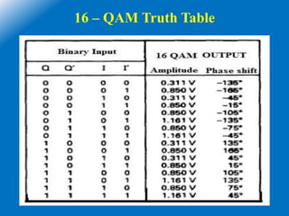
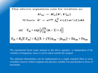
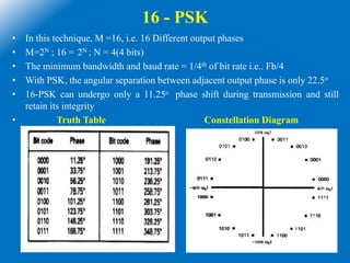
![16 - QAM
• Here M = 16, 16 = 2N,then N=4
• The minimum bandwidth and baud rate = one fourth of the bit rate = fb/4
• The fundamental frequency fa = fb/2 , but fb = fb/4
• fa = (fb/4)/2 = fb/8
• Output of the balanced modulator = Sinωat x Sinωct
=
Where fa = fb/8
• The output frequency spectrum ranges are (fc-fb/8) to (fc+fb/8)
• Minimum bandwidth or Nyquist bandwidth is
B = (fc+fb/8) – (fc-fb/8)
= fb/4
]t)ff(2[Cos
2
1
]t)ff(2[Cos
2
1
acac ](https://image.slidesharecdn.com/unit3-marysignaling-200830191642/85/EC-8395-Communication-Engineering-Unit-3-m-ary-signaling-30-320.jpg)