Downloaded 158 times
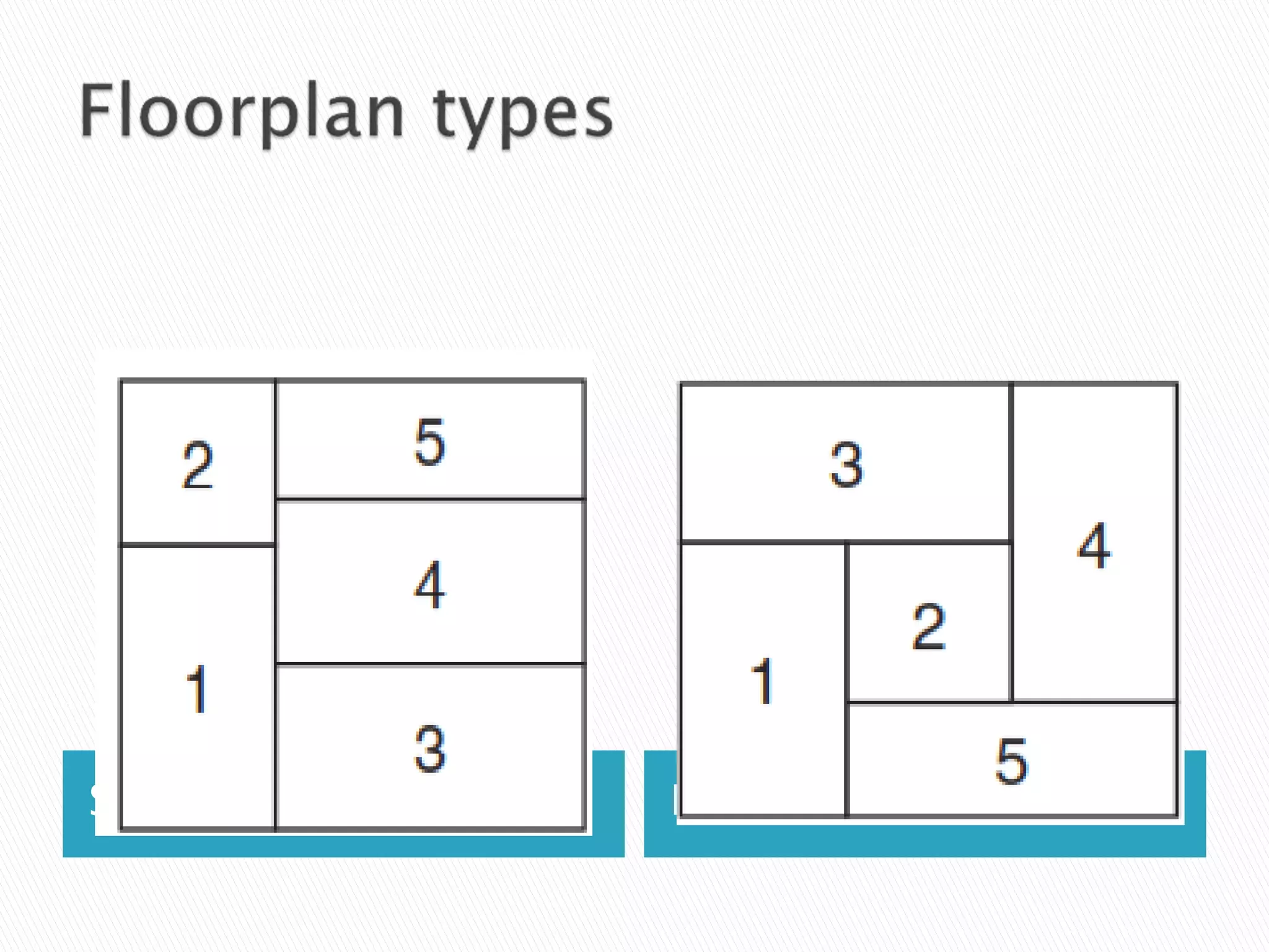

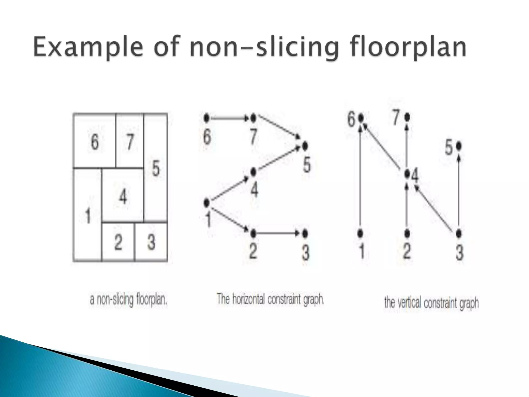
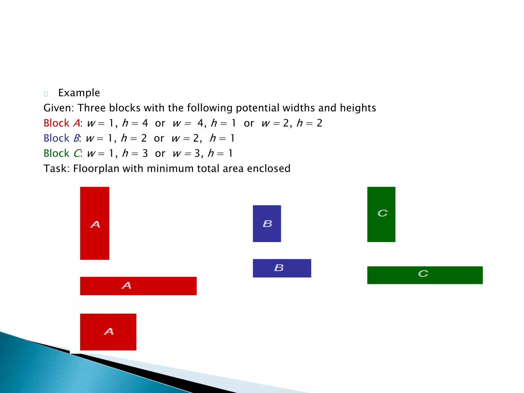


This document discusses floorplanning, which is an important first step in physical design. There are two main approaches to floorplanning: simulated annealing and analytical formulation. Popular representations of geometric relationships used in floorplanning are normalized Polish expression, B*-tree, and sequence pair. The goal of floorplanning is to optimize metrics like area and wire length. Slicing floorplans can be represented by binary trees, while non-slicing floorplans use constraint graphs.