This document outlines the use of a GUI for DRV Fix in ICC2, aimed at simplifying the process of fixing secondary violations. Users need to source the GUI, select appropriate input and output files (either nets or report files), and can perform operations like adding buffers or cloning instances through various steps detailed within the guide. The document includes instructions for file selection, navigation within the GUI, and the procedures for modifying net cells and implementing ECOs.
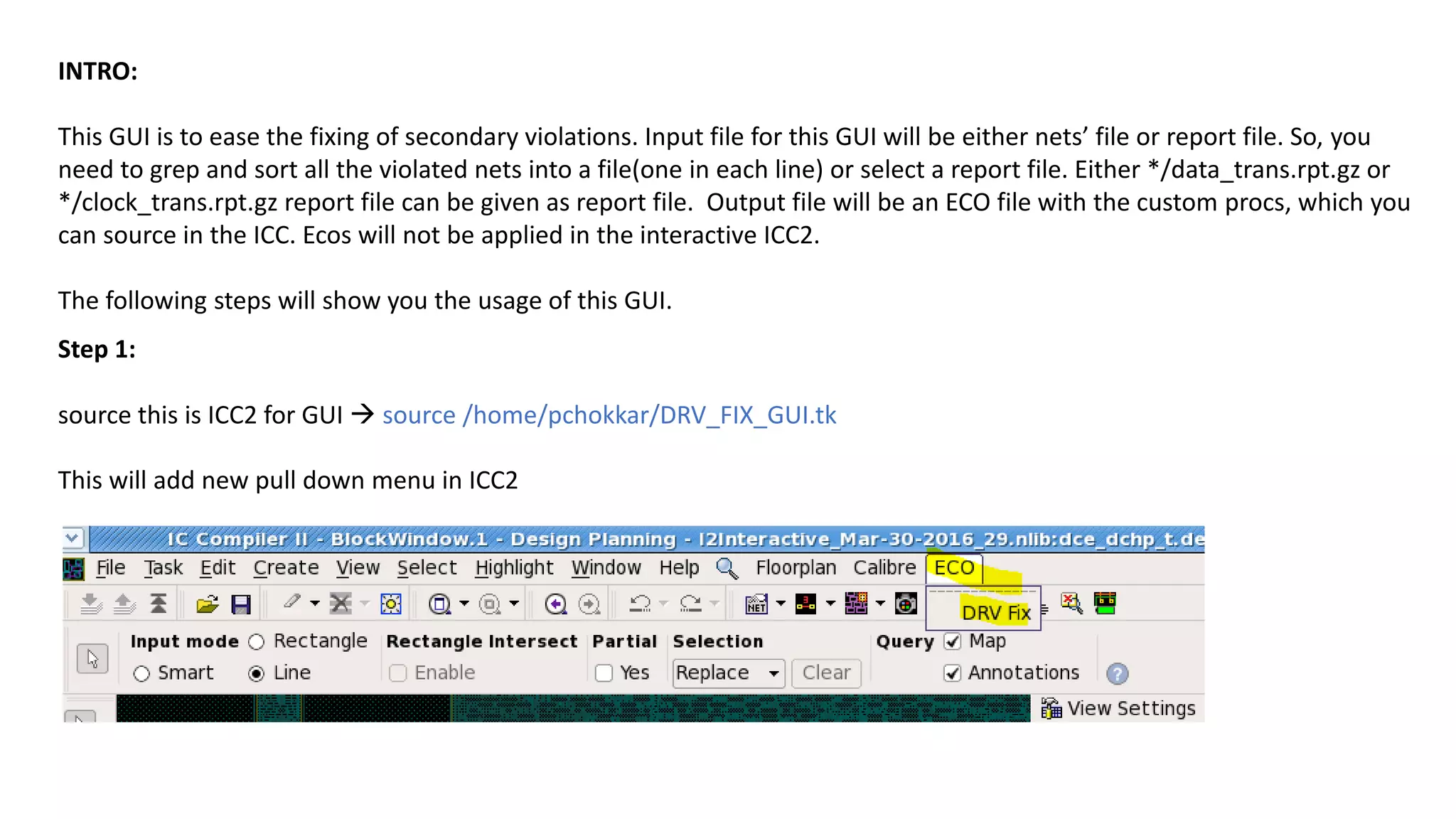
Step 1:
source thisis ICC2 for GUI source /home/pchokkar/DRV_FIX_GUI.tk
This will add new pull down menu in ICC2
INTRO:
This GUI is to ease the fixing of secondary violations. Input file for this GUI will be either nets’ file or report file. So, you
need to grep and sort all the violated nets into a file(one in each line) or select a report file. Either */data_trans.rpt.gz or
*/clock_trans.rpt.gz report file can be given as report file. Output file will be an ECO file with the custom procs, which you
can source in the ICC. Ecos will not be applied in the interactive ICC2.
The following steps will show you the usage of this GUI.
3.
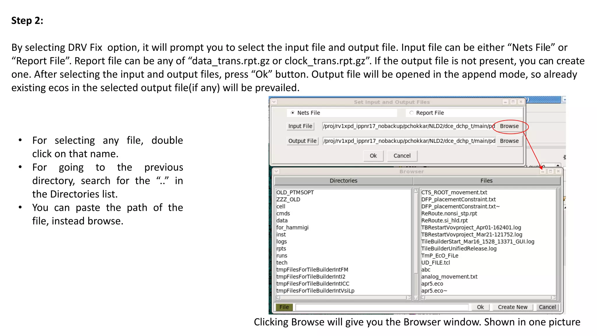
Step 2:
By selectingDRV Fix option, it will prompt you to select the input file and output file. Input file can be either “Nets File” or
“Report File”. Report file can be any of “data_trans.rpt.gz or clock_trans.rpt.gz”. If the output file is not present, you can create
one. After selecting the input and output files, press “Ok” button. Output file will be opened in the append mode, so already
existing ecos in the selected output file(if any) will be prevailed.
Clicking Browse will give you the Browser window. Shown in one picture
• For selecting any file, double
click on that name.
• For going to the previous
directory, search for the “..” in
the Directories list.
• You can paste the path of the
file, instead browse.
4.
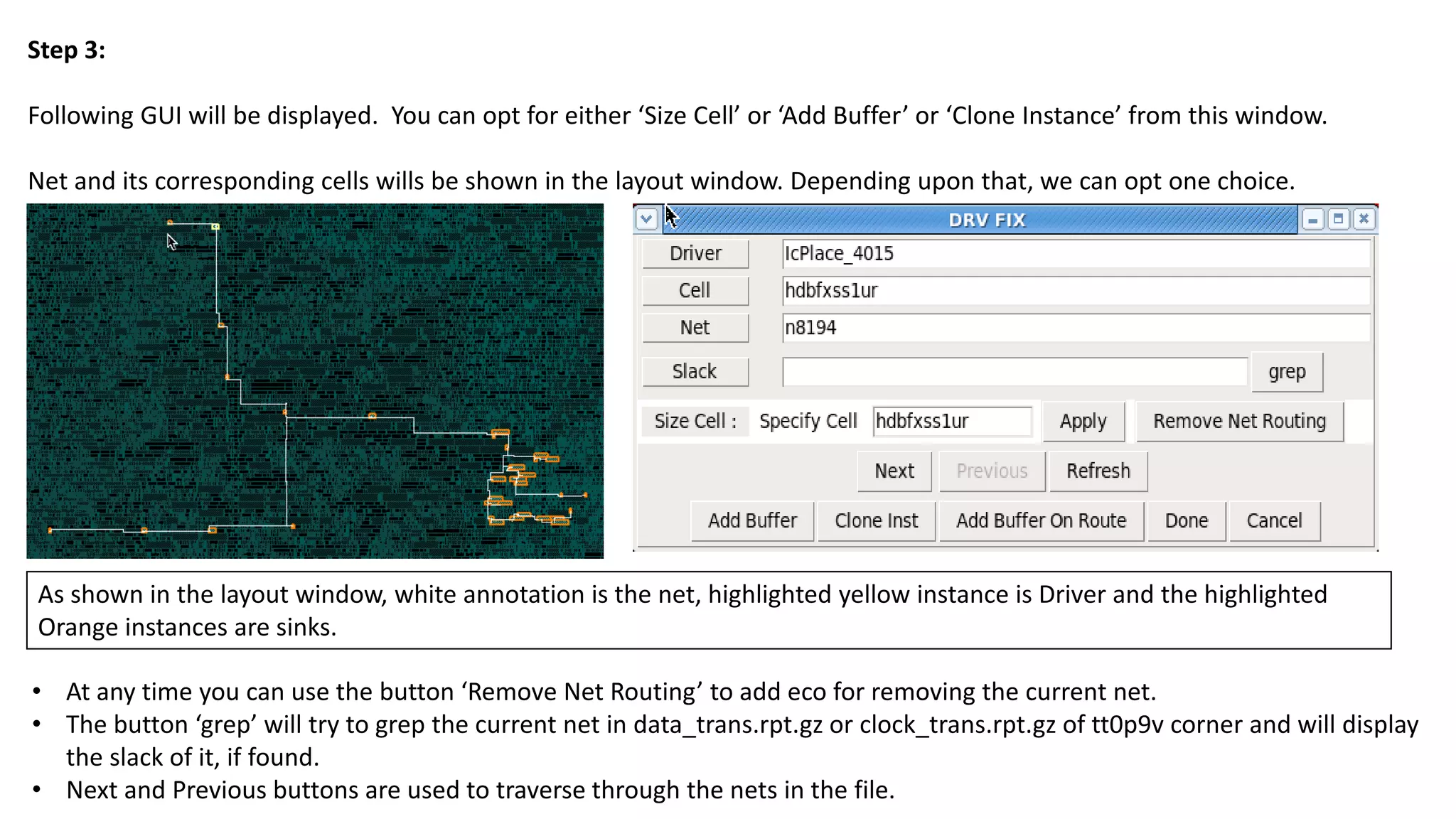
Step 3:
Following GUIwill be displayed. You can opt for either ‘Size Cell’ or ‘Add Buffer’ or ‘Clone Instance’ from this window.
Net and its corresponding cells wills be shown in the layout window. Depending upon that, we can opt one choice.
• At any time you can use the button ‘Remove Net Routing’ to add eco for removing the current net.
• The button ‘grep’ will try to grep the current net in data_trans.rpt.gz or clock_trans.rpt.gz of tt0p9v corner and will display
the slack of it, if found.
• Next and Previous buttons are used to traverse through the nets in the file.
As shown in the layout window, white annotation is the net, highlighted yellow instance is Driver and the highlighted
Orange instances are sinks.
5.
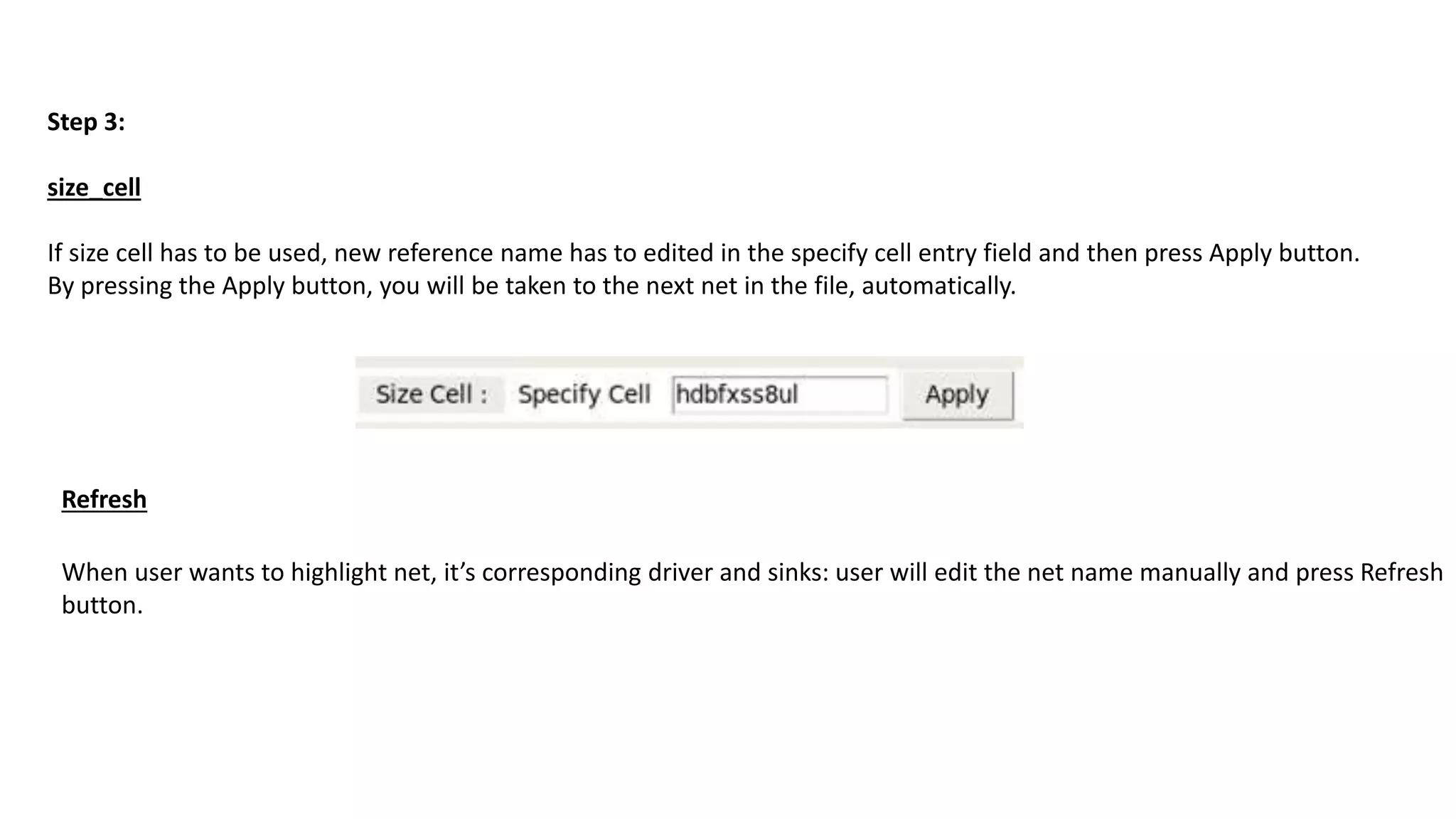
Step 3:
size_cell
If sizecell has to be used, new reference name has to edited in the specify cell entry field and then press Apply button.
By pressing the Apply button, you will be taken to the next net in the file, automatically.
When user wants to highlight net, it’s corresponding driver and sinks: user will edit the net name manually and press Refresh
button.
Refresh
6.
Step 3:
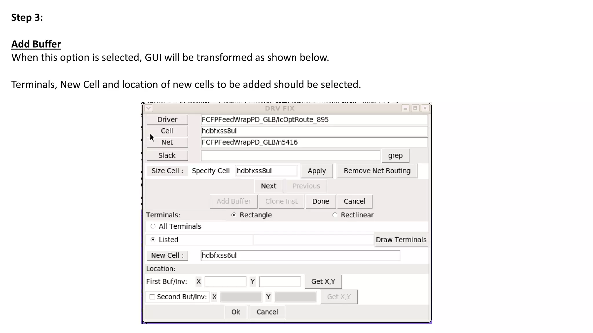
Add Buffer
Whenthis option is selected, GUI will be transformed as shown below.
Terminals, New Cell and location of new cells to be added should be selected.
7.
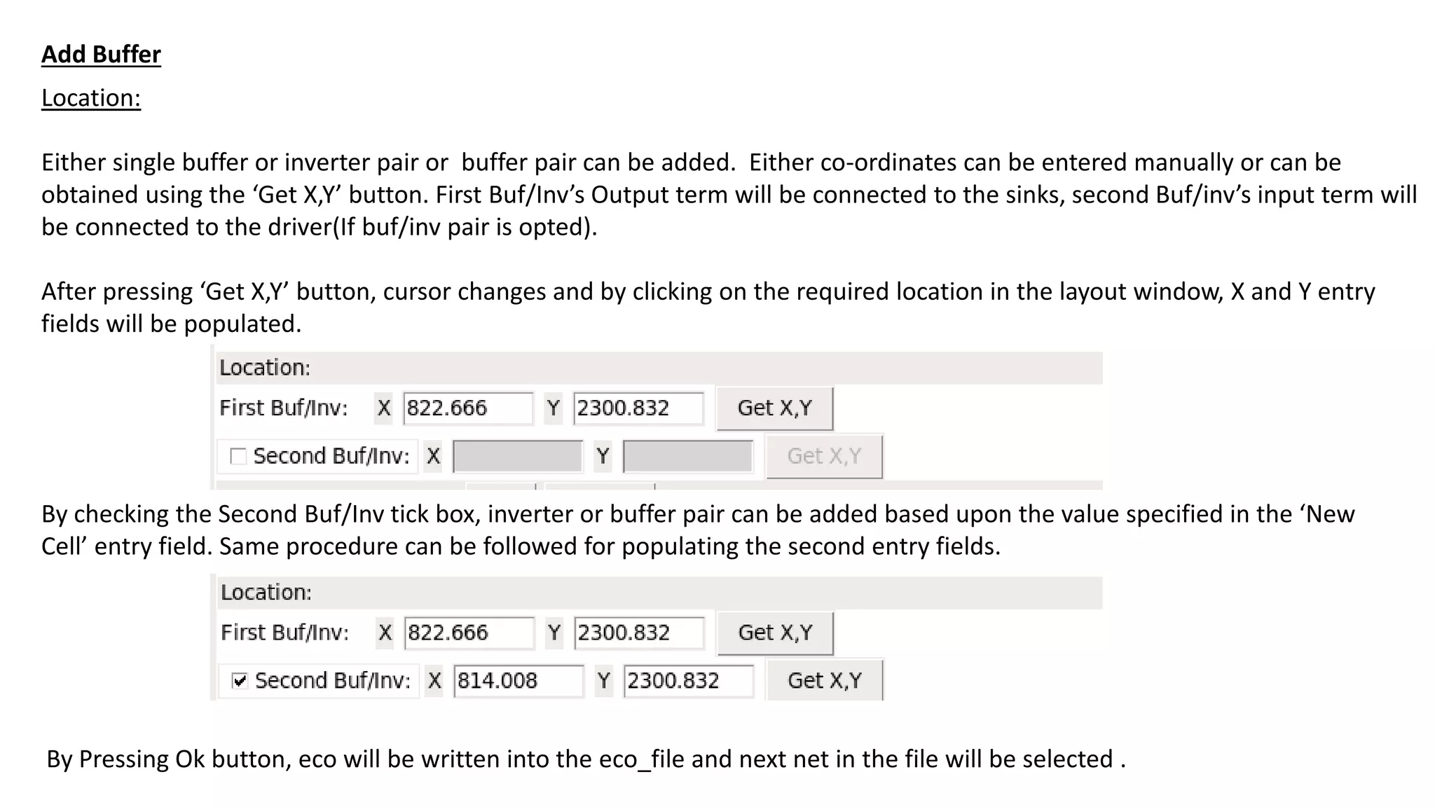
Location:
Either single bufferor inverter pair or buffer pair can be added. Either co-ordinates can be entered manually or can be
obtained using the ‘Get X,Y’ button. First Buf/Inv’s Output term will be connected to the sinks, second Buf/inv’s input term will
be connected to the driver(If buf/inv pair is opted).
After pressing ‘Get X,Y’ button, cursor changes and by clicking on the required location in the layout window, X and Y entry
fields will be populated.
By checking the Second Buf/Inv tick box, inverter or buffer pair can be added based upon the value specified in the ‘New
Cell’ entry field. Same procedure can be followed for populating the second entry fields.
By Pressing Ok button, eco will be written into the eco_file and next net in the file will be selected .
Add Buffer
8.
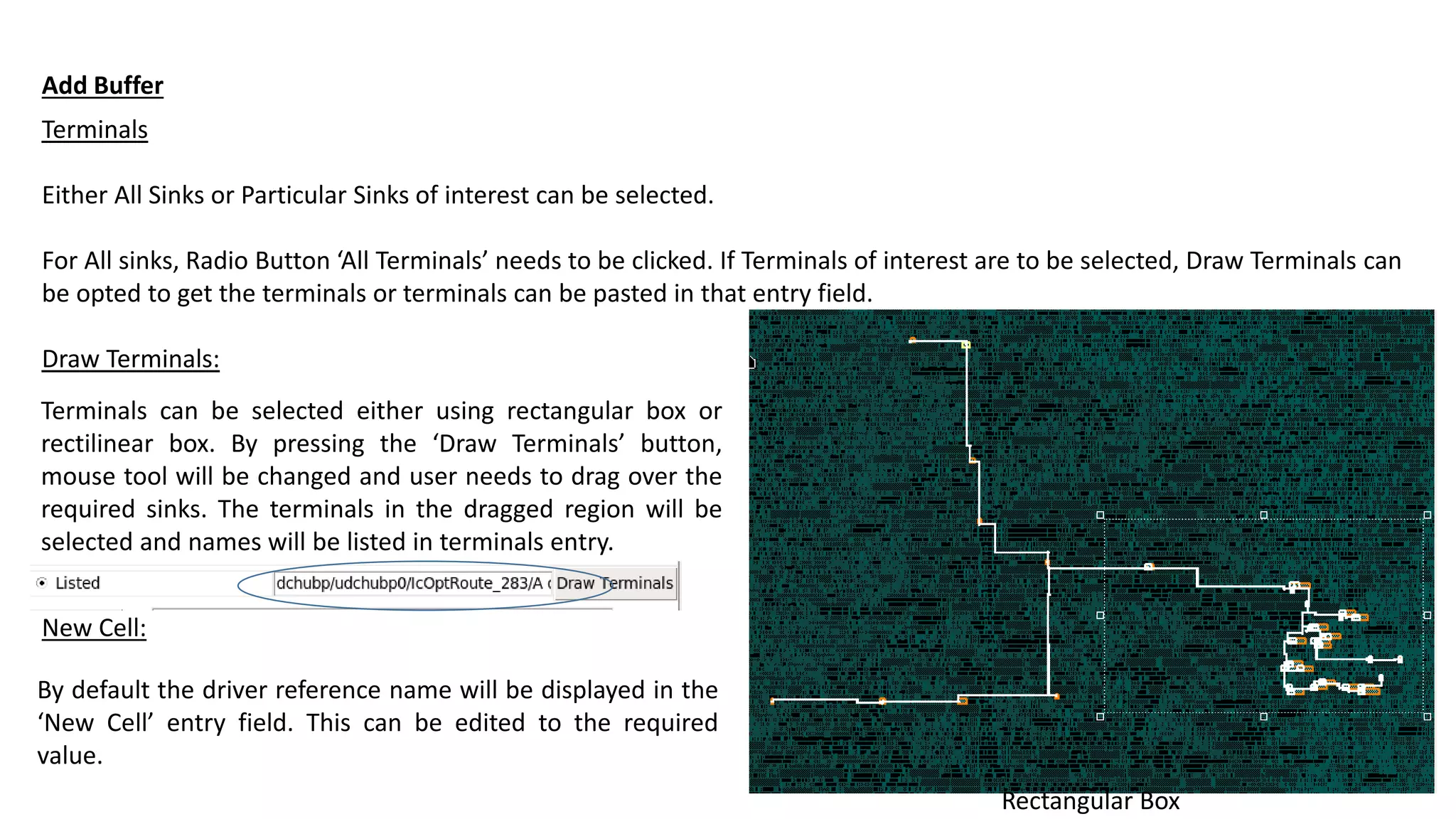
Terminals
Either All Sinksor Particular Sinks of interest can be selected.
For All sinks, Radio Button ‘All Terminals’ needs to be clicked. If Terminals of interest are to be selected, Draw Terminals can
be opted to get the terminals or terminals can be pasted in that entry field.
Draw Terminals:
Add Buffer
Terminals can be selected either using rectangular box or
rectilinear box. By pressing the ‘Draw Terminals’ button,
mouse tool will be changed and user needs to drag over the
required sinks. The terminals in the dragged region will be
selected and names will be listed in terminals entry.
Rectangular Box
New Cell:
By default the driver reference name will be displayed in the
‘New Cell’ entry field. This can be edited to the required
value.
9.
Location:
Either single bufferor inverter pair or buffer pair can be added. Either co-ordinates can be entered manually or can be
obtained using the ‘Get X,Y’ button. First Buf/Inv’s Output term will be connected to the sinks, second Buf/inv’s input term will
be connected to the driver(If buf/inv pair is opted).
After pressing ‘Get X,Y’ button, cursor changes and by clicking on the required location in the layout window, X and Y entry
fields will be populated.
By checking the Second Buf/Inv tick box, inverter or buffer pair can be added based upon the value specified in the ‘New
Cell’ entry field. Same procedure can be followed for populating the second entry fields.
By Pressing Ok button, eco will be written into the eco_file and next net in the file will be selected .
Add Buffer
10.
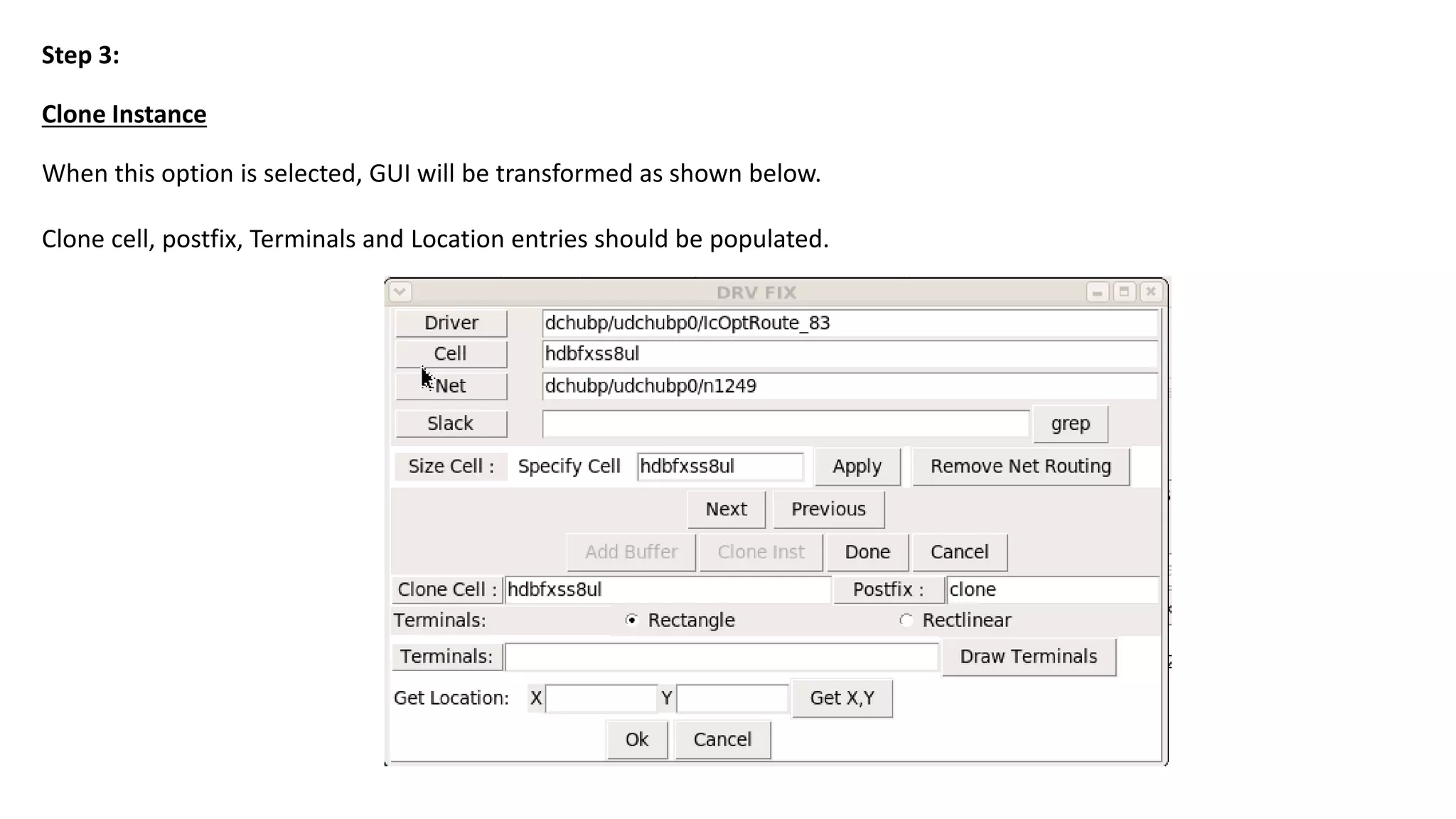
Clone Instance
Step 3:
Whenthis option is selected, GUI will be transformed as shown below.
Clone cell, postfix, Terminals and Location entries should be populated.
11.
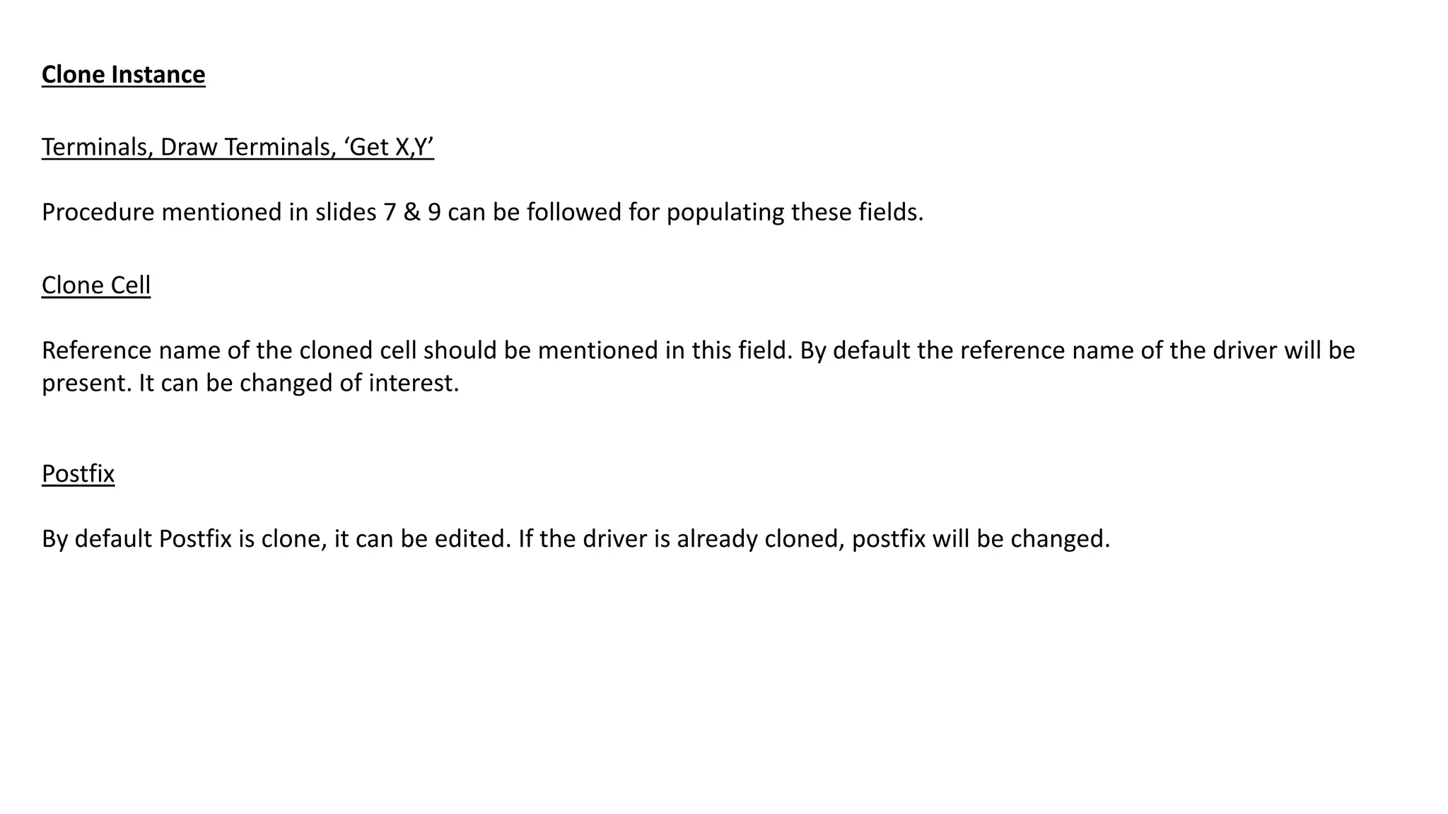
Terminals, Draw Terminals,‘Get X,Y’
Procedure mentioned in slides 7 & 9 can be followed for populating these fields.
Clone Instance
Clone Cell
Reference name of the cloned cell should be mentioned in this field. By default the reference name of the driver will be
present. It can be changed of interest.
Postfix
By default Postfix is clone, it can be edited. If the driver is already cloned, postfix will be changed.
12.
Step 3:
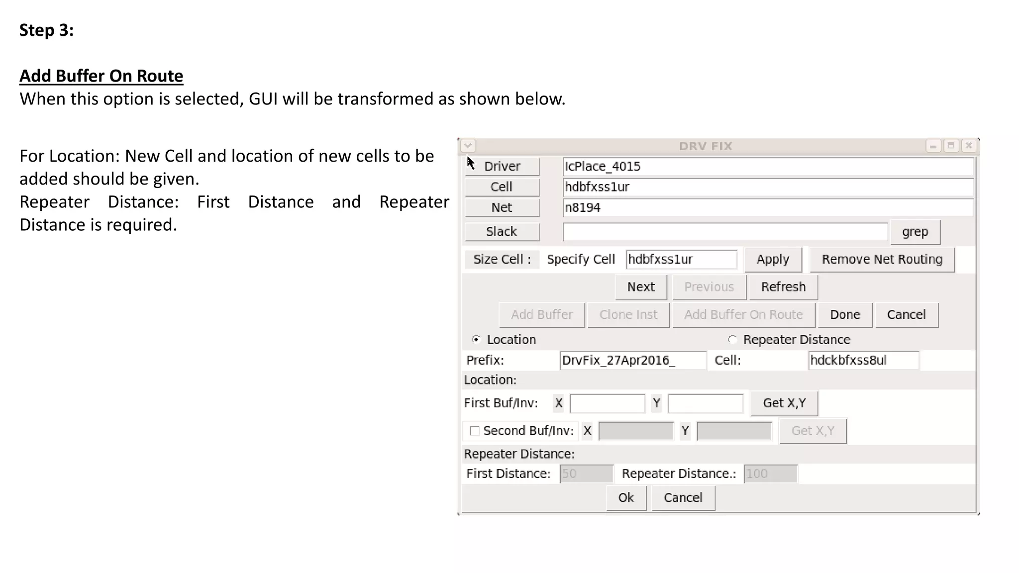
Add BufferOn Route
When this option is selected, GUI will be transformed as shown below.
For Location: New Cell and location of new cells to be
added should be given.
Repeater Distance: First Distance and Repeater
Distance is required.
13.
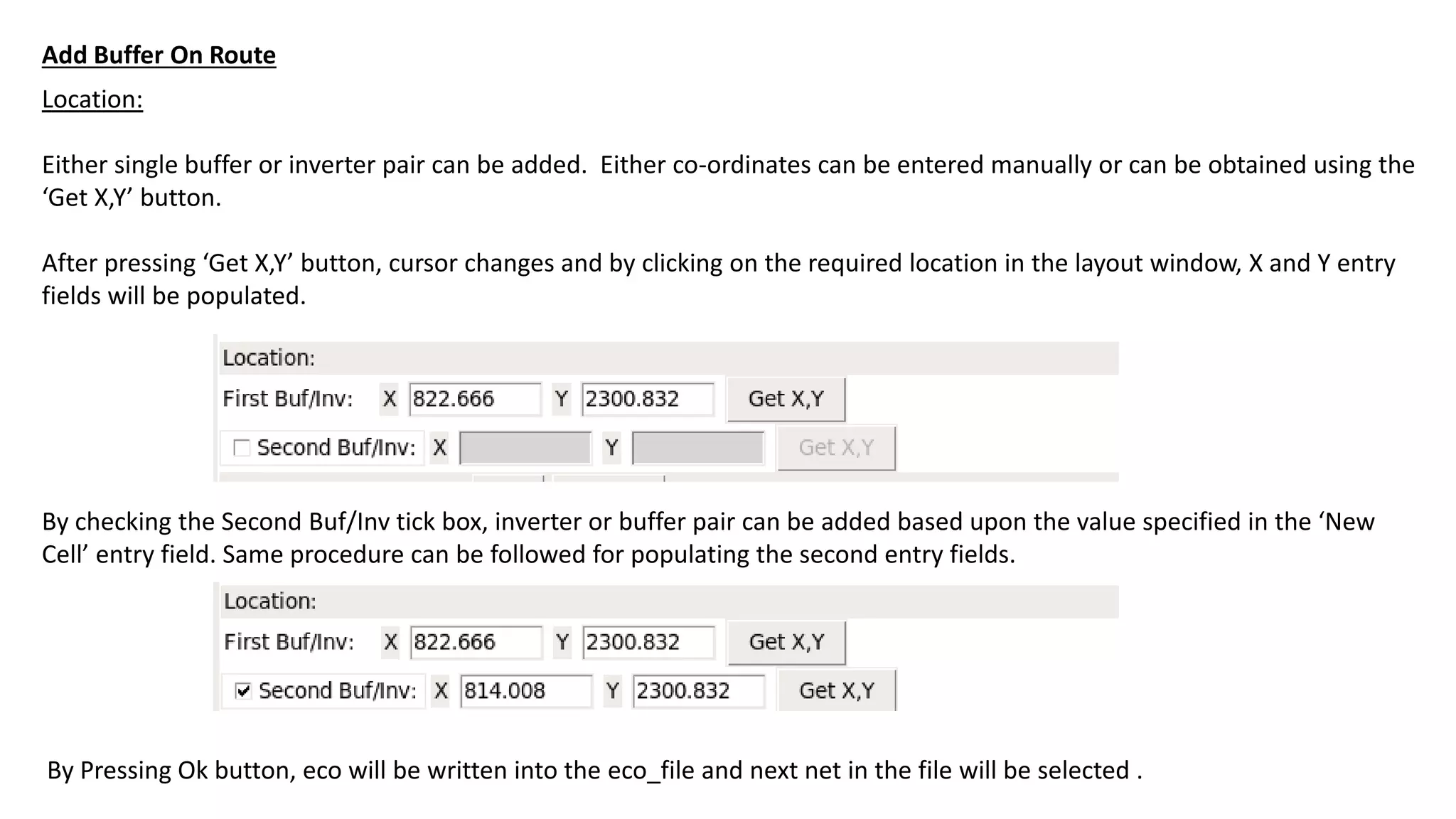
Location:
Either single bufferor inverter pair can be added. Either co-ordinates can be entered manually or can be obtained using the
‘Get X,Y’ button.
After pressing ‘Get X,Y’ button, cursor changes and by clicking on the required location in the layout window, X and Y entry
fields will be populated.
By checking the Second Buf/Inv tick box, inverter or buffer pair can be added based upon the value specified in the ‘New
Cell’ entry field. Same procedure can be followed for populating the second entry fields.
By Pressing Ok button, eco will be written into the eco_file and next net in the file will be selected .
Add Buffer On Route
14.
Repeater Distance:
First Distanceand Repeater Distance should be specified.
Use this carefully. When fanout is single we will face no
issue.
Add Buffer On Route
Prefix
By default Prefix will be DrvFix_[date]_ , it can be
edited.
Cell
New cell added should be given. It should be either
buffer or inverter.


![Repeater Distance:
First Distance and Repeater Distance should be specified.
Use this carefully. When fanout is single we will face no
issue.
Add Buffer On Route
Prefix
By default Prefix will be DrvFix_[date]_ , it can be
edited.
Cell
New cell added should be given. It should be either
buffer or inverter.](https://image.slidesharecdn.com/guifordrvfix-160802204229/75/GUI-for-DRV-fix-in-ICC2-14-2048.jpg)