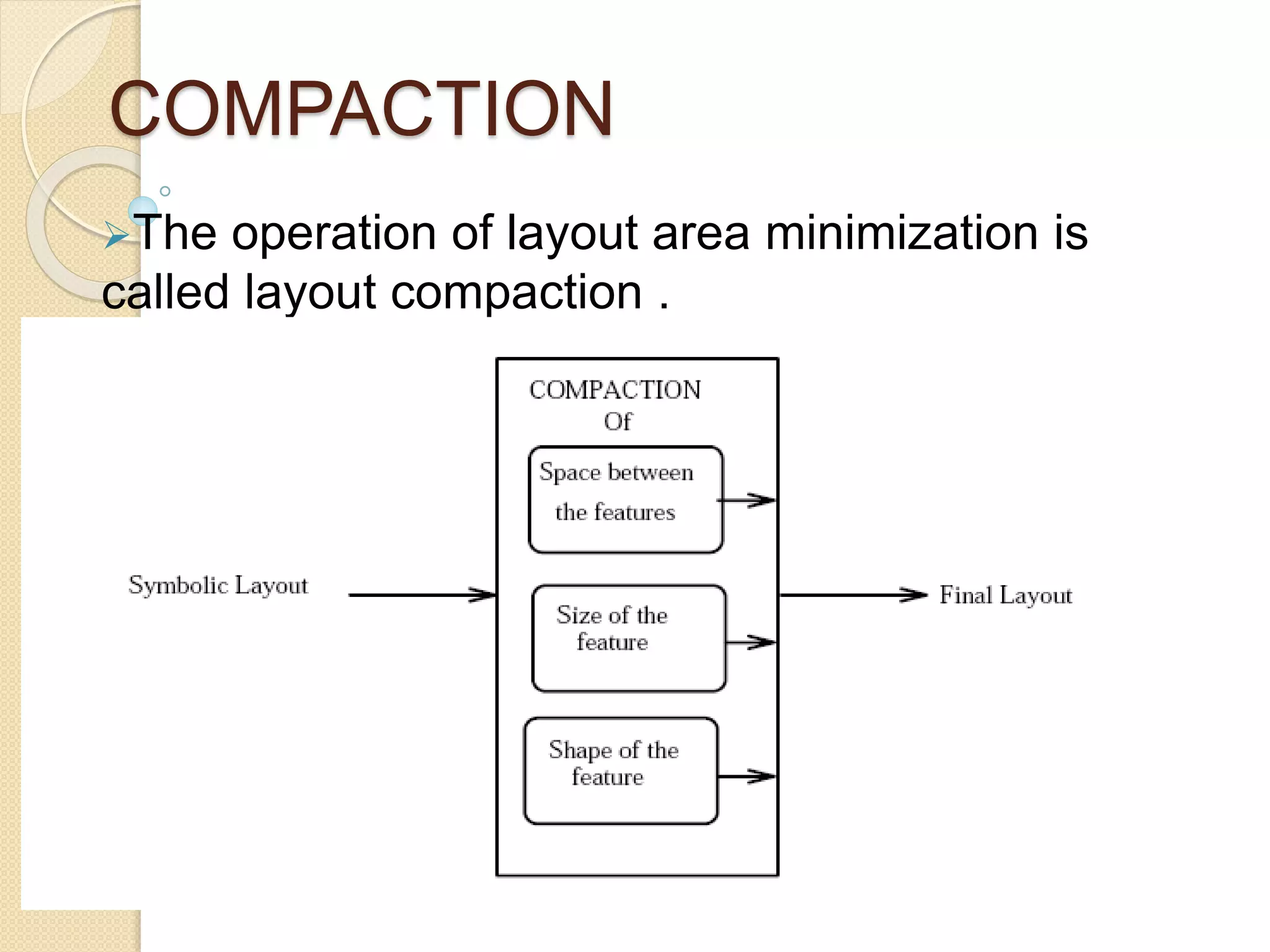
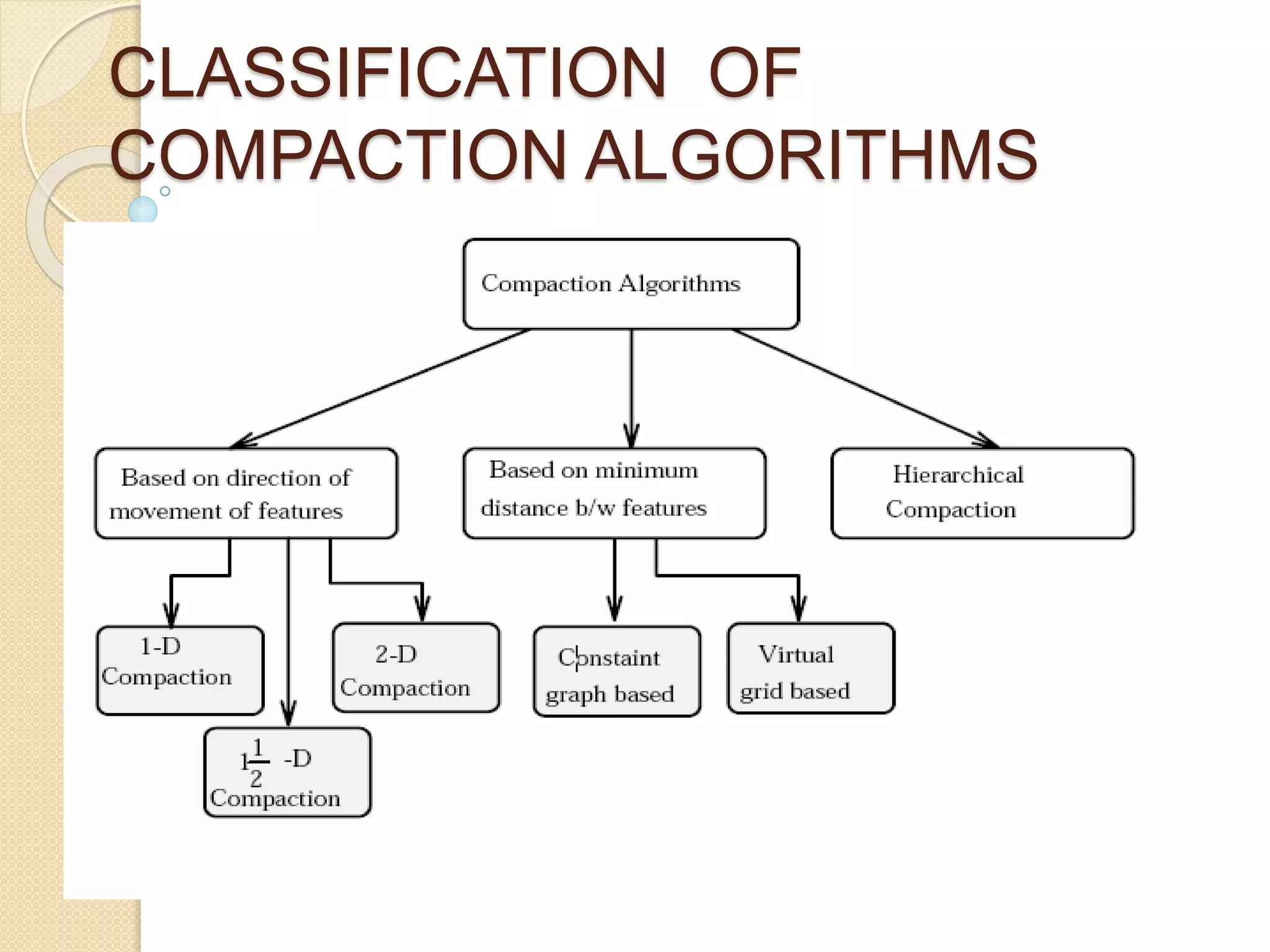
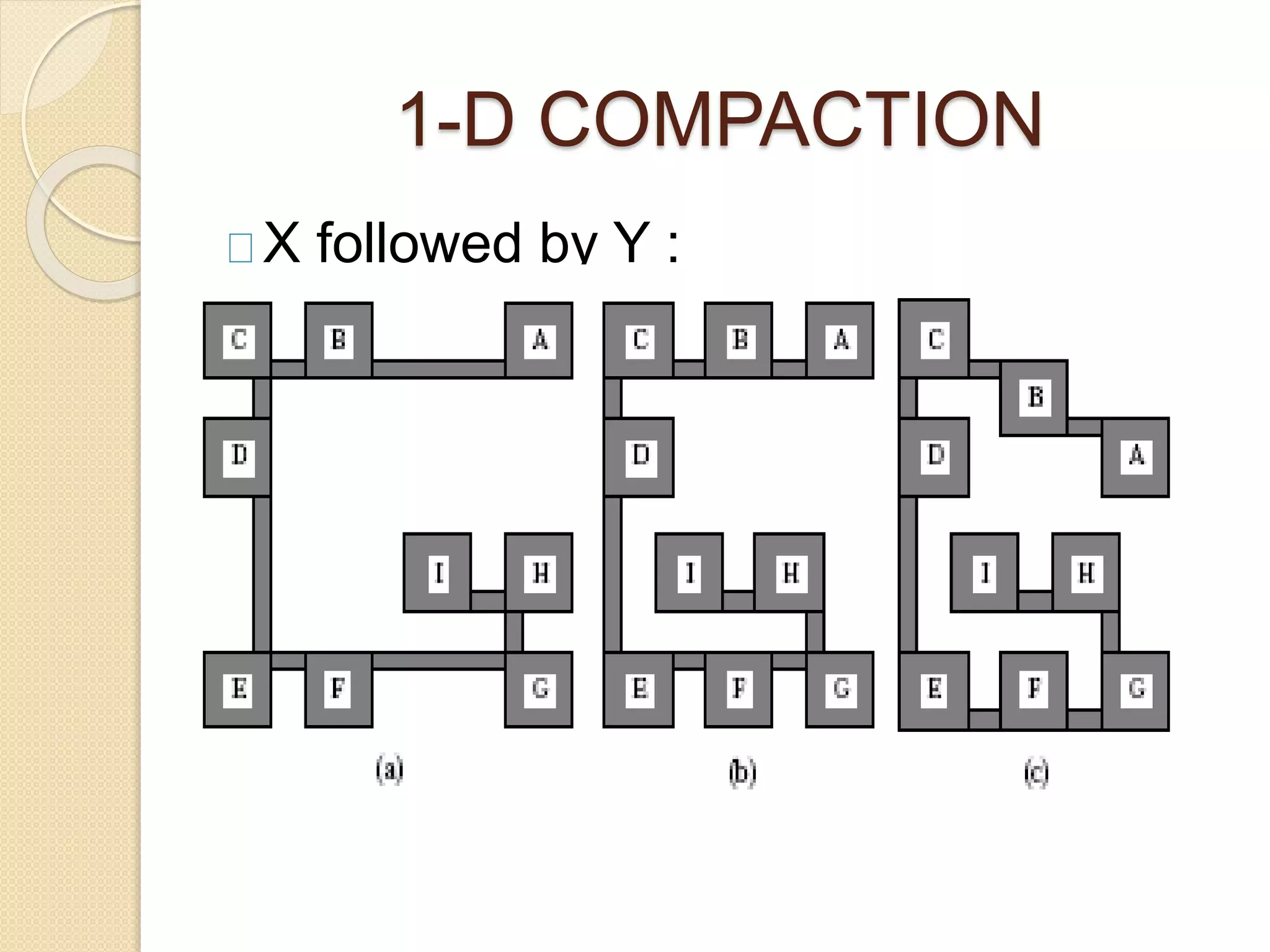
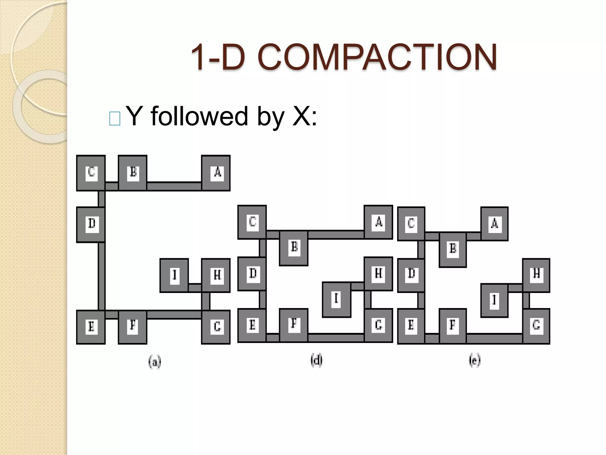
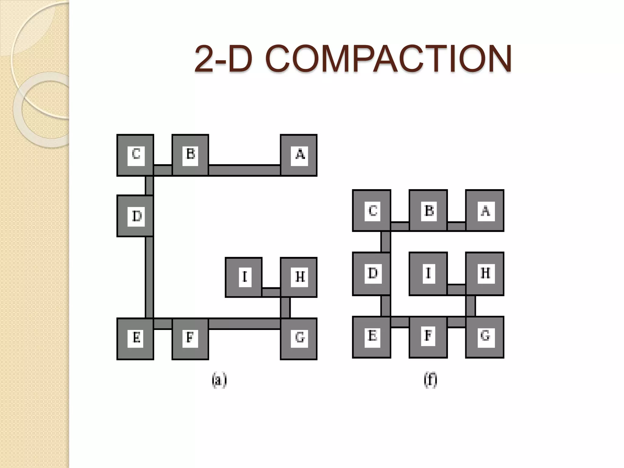
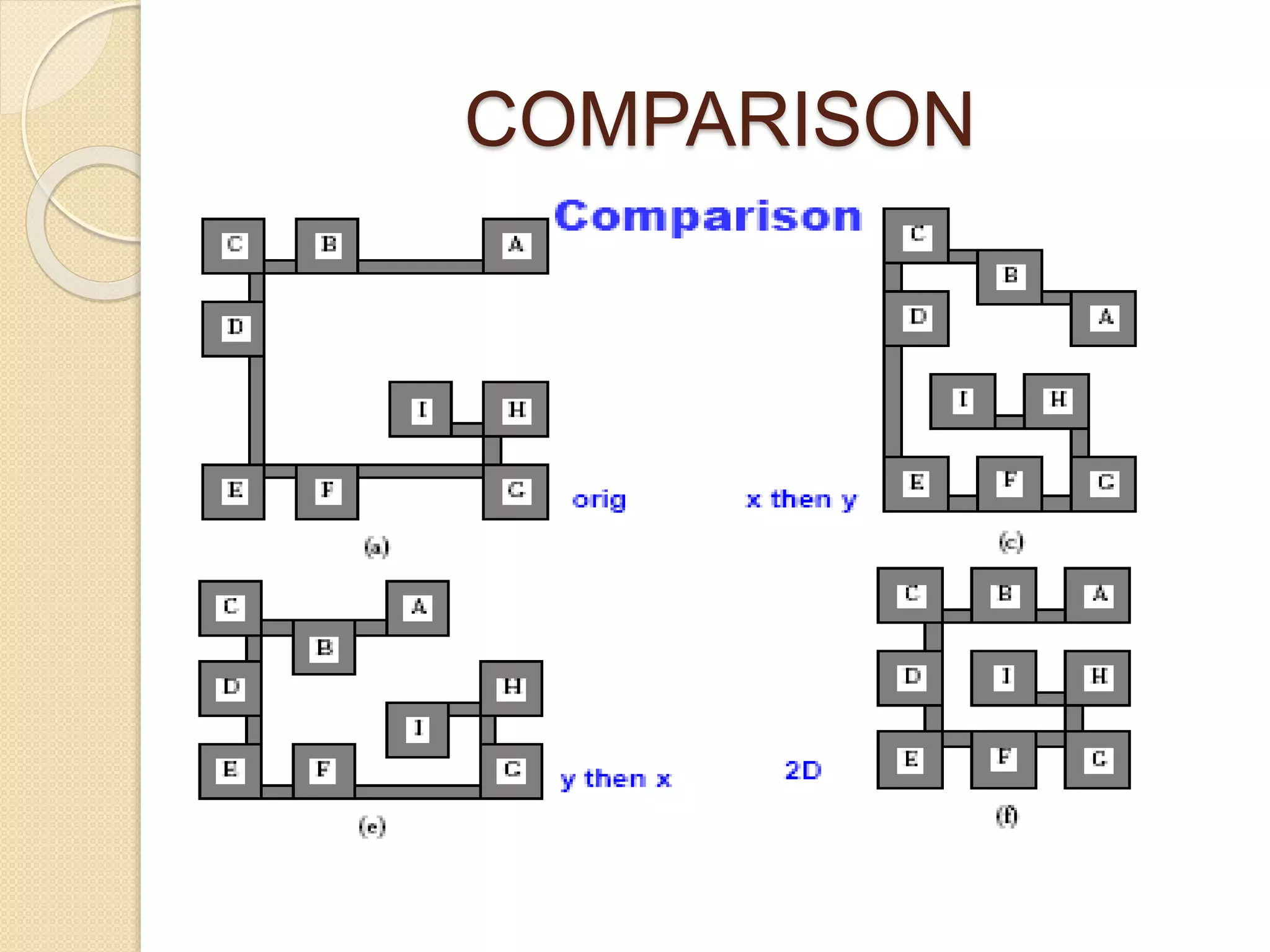
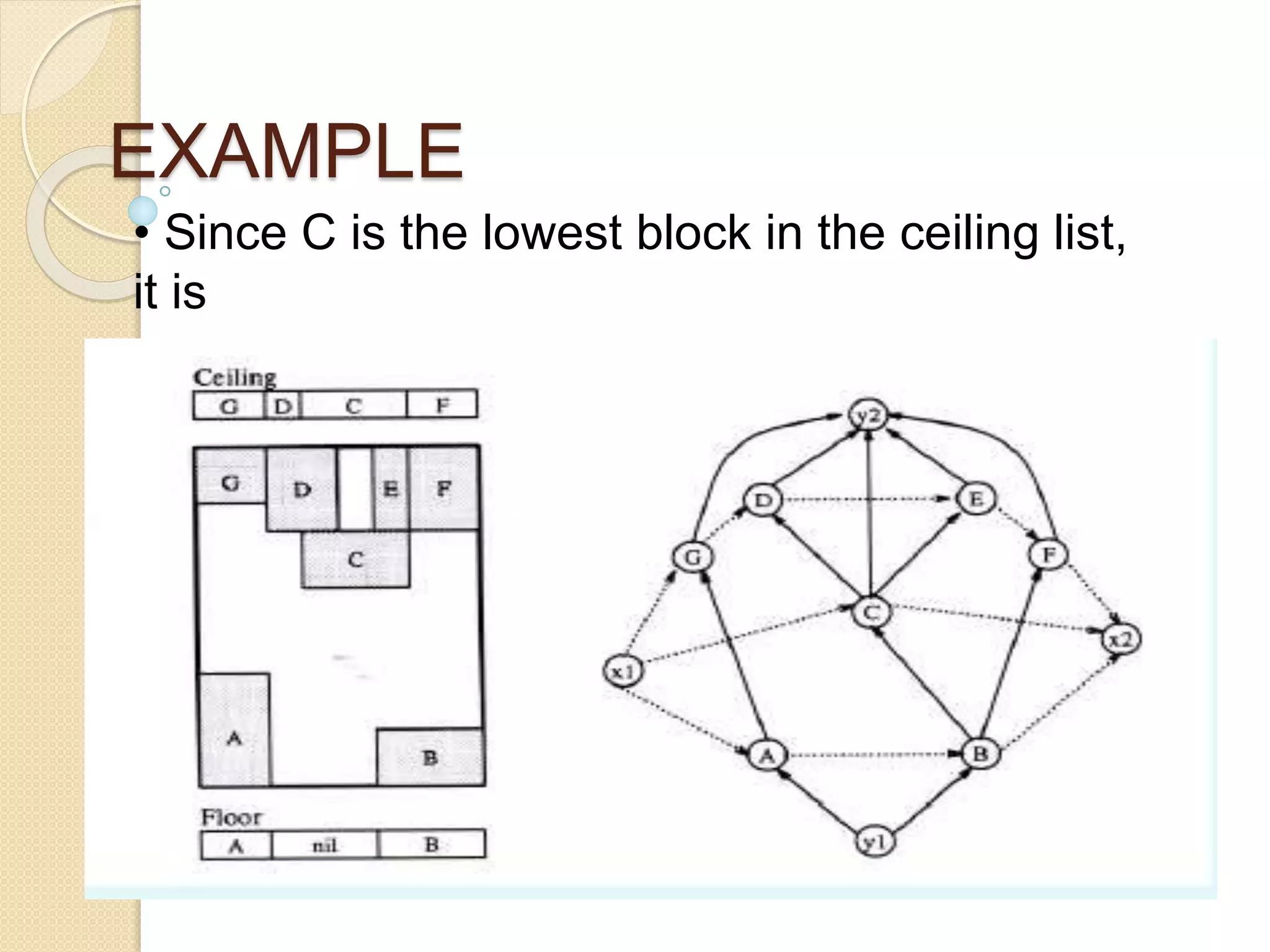
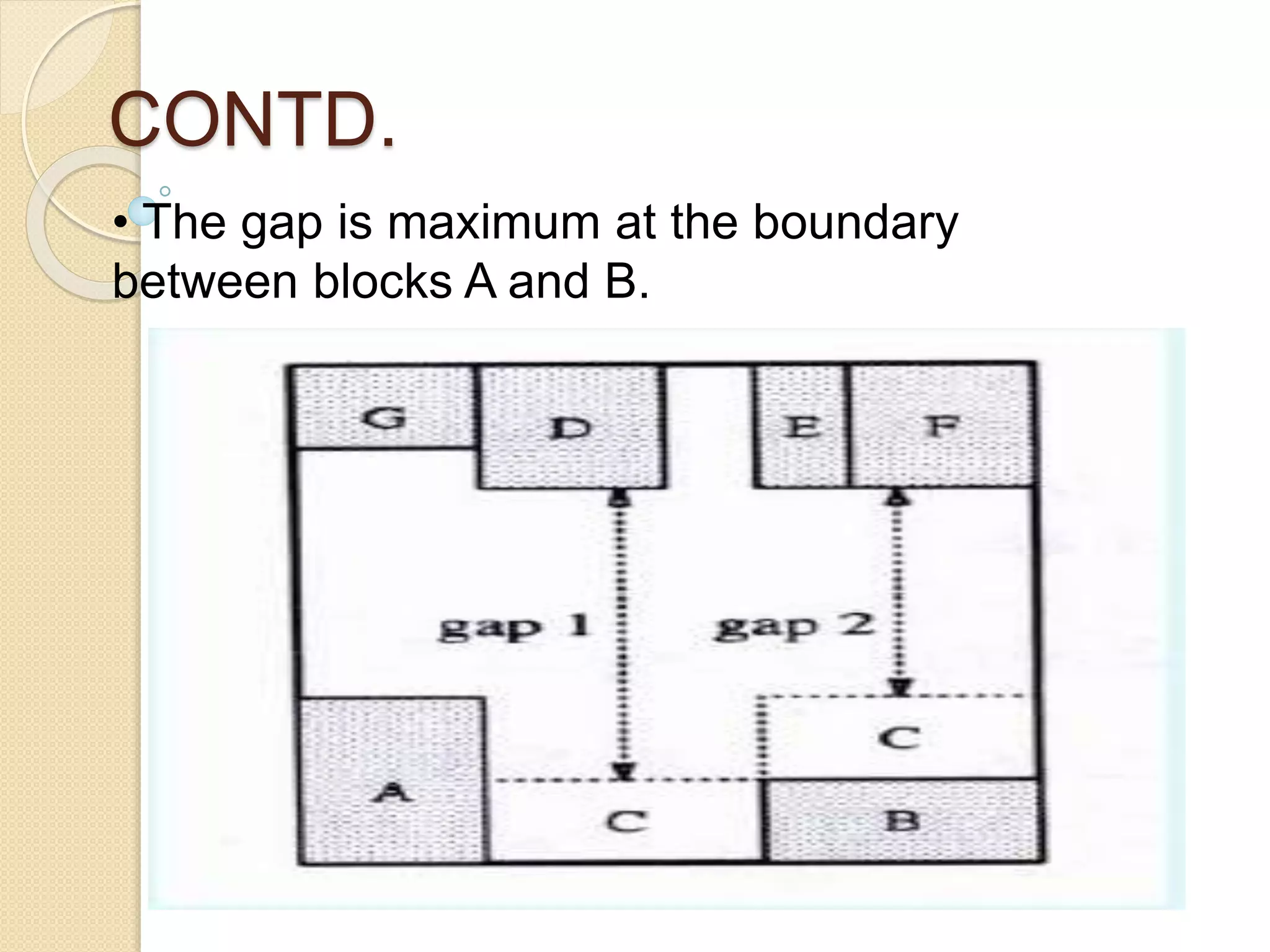
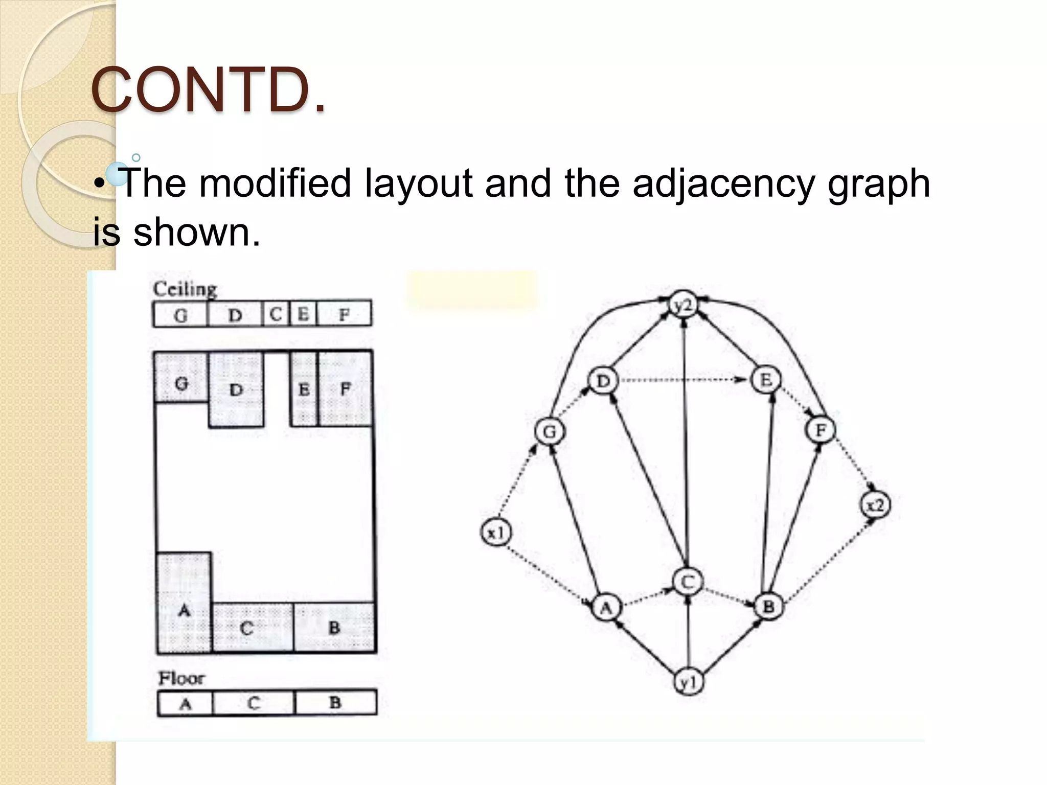
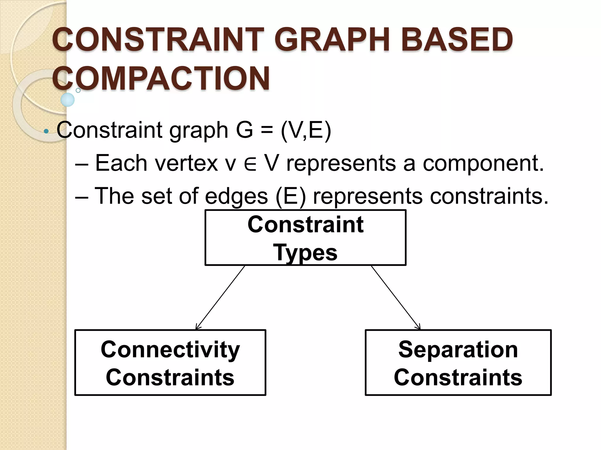
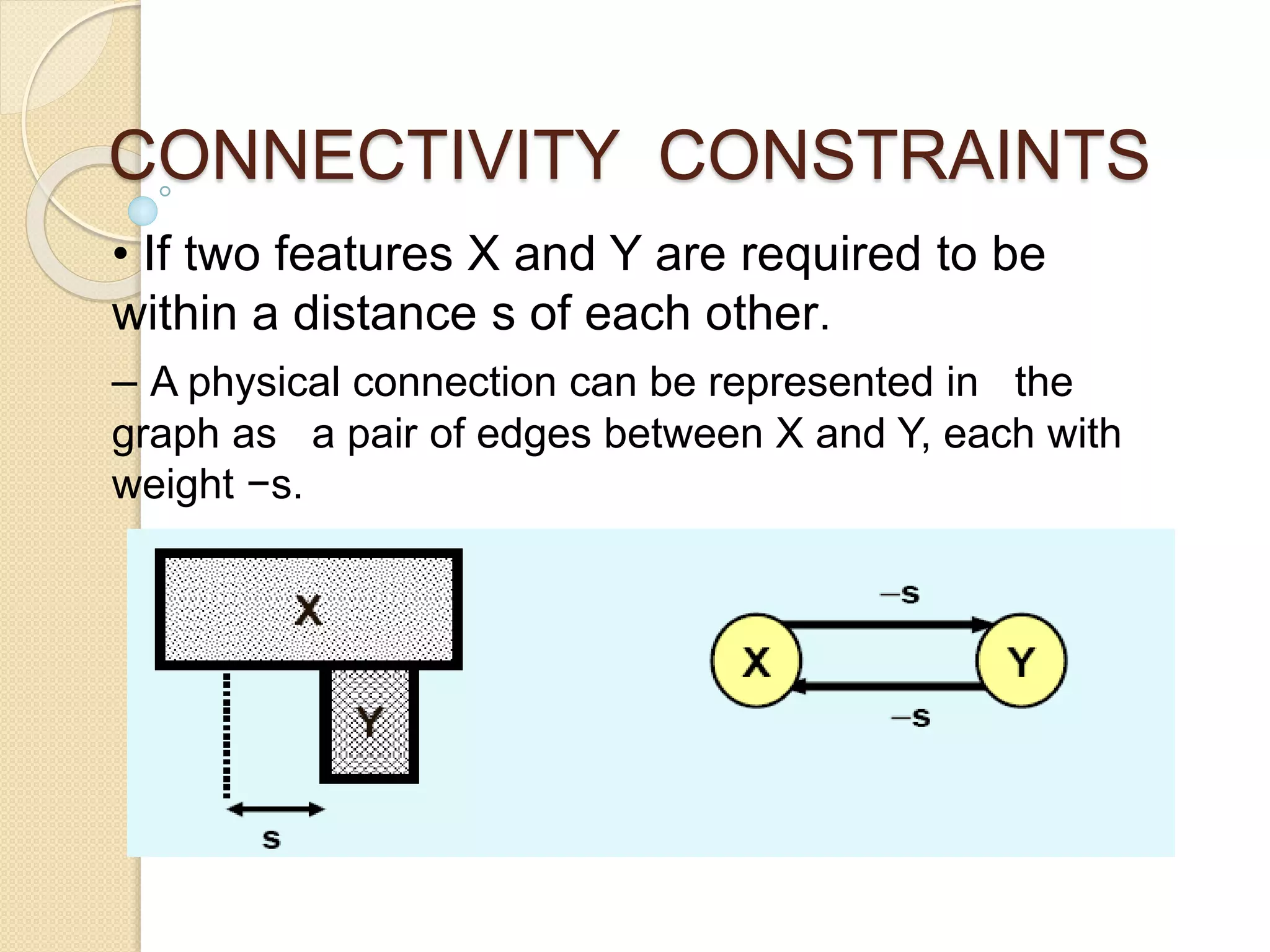
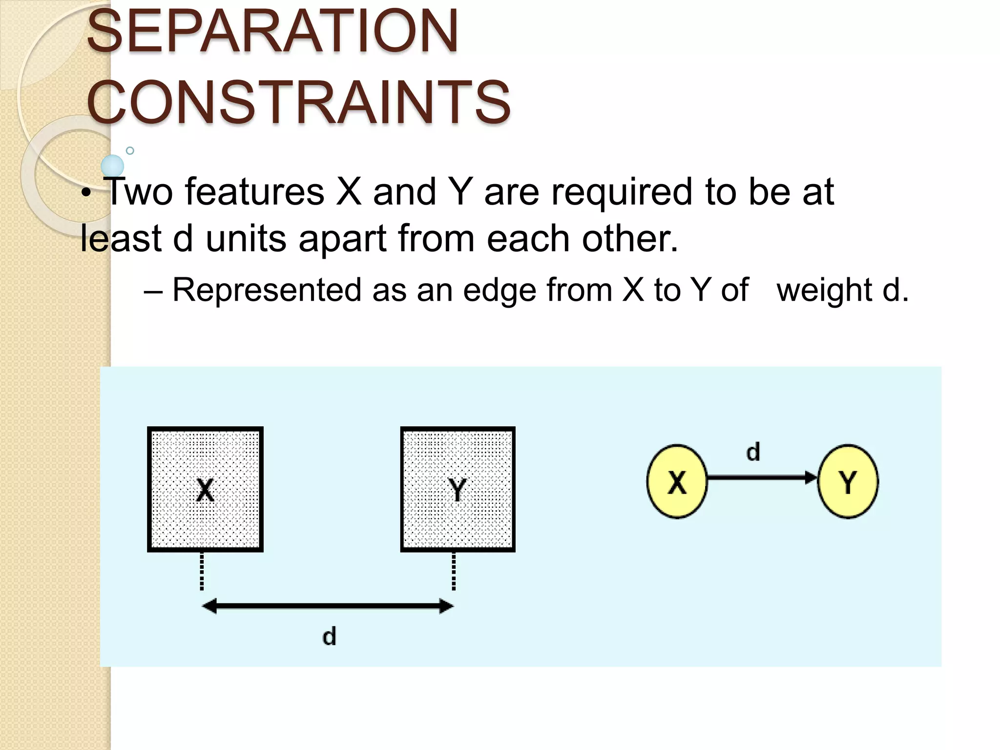
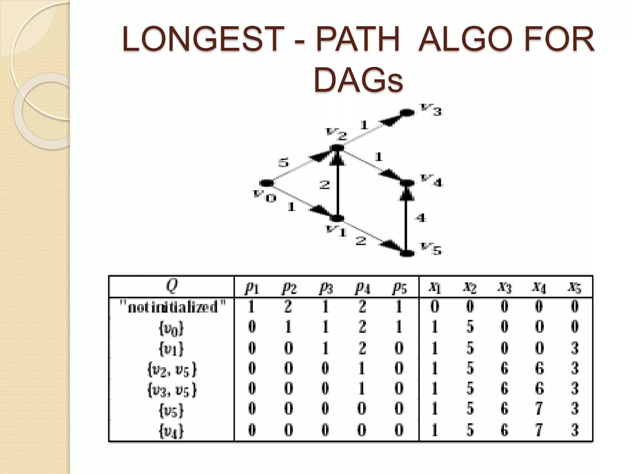
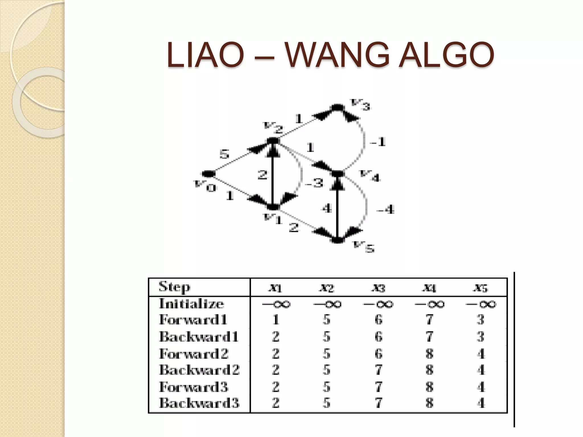
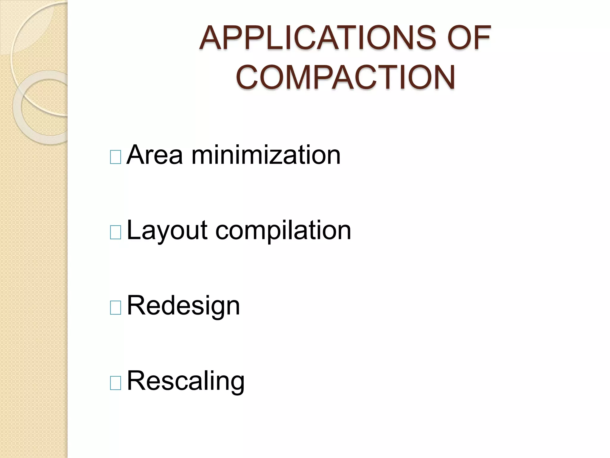
4. PROBLEM FORMULATION
• Given:
– A set of geometric features M = {M1, M2, ….., Mn}.
– The minimum feature size, s(Mi), for all i.
– The minimum separation between features Mi and
Mj,
d(Mi,Mj).
• Objective:
– Minimize the layout such that
size(Mi) ≥ s(Mi)
dist(Mi,Mj) ≥ d(Mi,Mj)
where size(Mi) and dist(Mi,Mj) are size of Mi and
distance
between Mi and Mj after the compaction, where 1 ≤ i,j
≤ n.
7. 2- DIMENSIONAL COMPACTION
• 2-D compaction is in general much better
than
performing 1-D compaction.
• 2-D compaction, if solved optimally, produces
minimum-area layouts.
– It is very time consuming.
– Thus 1½-D compaction techniques have been
proposed.
• Perform x-direction compaction moves while
making small moves in the y-direction.
10. 1½- DIMENSIONAL
COMPACTION
• A deterministic algorithm.
– Key idea is to provide enough lateral
movements to blocks during compaction to
resolve interferences.
• This is called 1½-dimensional compactor, since
the geometry is not as free as in true 2-
dimensional compaction.
11. EXAMPLE
• Since C is the lowest block in the ceiling list,
it is
selected for the move.
12. CONTD.
• The gap is maximum at the boundary
between blocks A and B.
14. CONSTRAINT GRAPH BASED
COMPACTION
• Constraint graph G = (V,E)
– Each vertex v ∈ V represents a component.
– The set of edges (E) represents constraints.
Constraint
Types
Connectivity
Constraints
Separation
Constraints
15. CONNECTIVITY CONSTRAINTS
• If two features X and Y are required to be
within a distance s of each other.
– A physical connection can be represented in the
graph as a pair of edges between X and Y, each with
weight −s.
16. SEPARATION
CONSTRAINTS
• Two features X and Y are required to be at
least d units apart from each other.
– Represented as an edge from X to Y of weight d.
Firstly compaction is done horizontally i.e. in X direction which is followed by vertical compaction i.e. in Y direction.
In 1D compaction ->layout elements only move or shrink in one dimension (x or y). Often sequentially performed first in the x-dimension and then in the y-dimension (or vice versa).
An example showing the layout compaction done by moving c block and placing it at a place to get the optimized layout as shown in the next two slides
P-> in degree of the respective node e.g. p1 shows the in degree of the node v1 ,p2 shows in degree of the node v2 and so on.
(In degree means the no. of edges entering that node ).
X1,x2……x5 shows the longest path from v0 to the node which is being processed .
The path 1->5->6->7->3 is the longest path .
Here we consider the longest forward and backward paths and continue until constant path values is found.