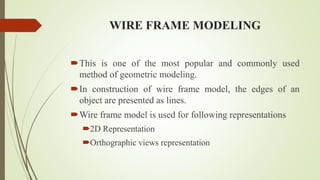
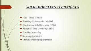
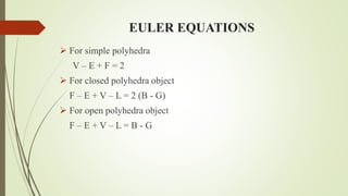
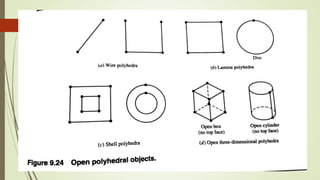
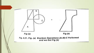
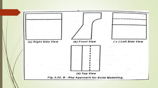
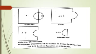
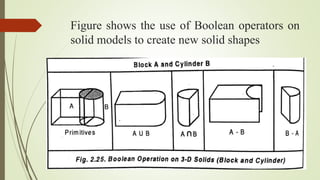
1. GEOMETRIC MODELING
The mathematical description of the geometry of an object
using a software is called as geometric modeling
There are three basic methods
Wire – Frame Modeling
Surface modeling
Solid modeling
2. WIRE FRAME MODELING
This is one of the most popular and commonly used
method of geometric modeling.
In construction of wire frame model, the edges of an
object are presented as lines.
Wire frame model is used for following representations
2D Representation
Orthographic views representation
3. 2D Wire Frame Model 3D Wire Frame Model
The co-ordinate system is 2D co-ordinate
system i.e. x and y co-ordinates only
3D co-ordinate system is used for
representing objects; x, y and z
coordinates are used
3 Dimensional wire frame system
generation is difficult
Both 2D and 3D wire frame
generation is possible
Hidden lines may not complicate the
figure
Difficult for the viewer to interpret the
figure unless the hidden lines are
removed
Curved surfaces are indicated by circles,
arcs and ellipses
Curved surfaces are represented by
spaced generators.
4. DRAWBACK OF WIRE FRAME MODEL
Lack of clarity
When part geometry is complex and in case of 3D wire
frame systems, the hidden lines causes the image to be
confusing to the viewer.
During the surface definition, there might be confusing.
By eliminating hidden lines, some clarity can be obtained.
5. SURFACE MODELING
The techniques of representation of objects (or) components by
surface is called surface modeling.
Objects can be clearly interpreted by the user.
Main draw back here is that, no data is available about the
interior of solid.
Application is modeling car bodies, ships, aerospace structure,
dies, etc.
6. TECHNIQUES AVAILABLE FOR SURFACE
MODELING
Surface patch
Coons patch
Bicubic patch
Bezier surfaces
B-spline surfaces
NURBS (Non-Uniform Rational B-Splines)
7. SURFACE PATCH
The building blocks of the surfaces are known as surface patch
Generally u and v are two variables used for representing a patch.
0 ≤ 𝑈 ≤ 1 𝑎𝑛𝑑 0 ≤ 𝑉 ≤ 1
8.
9. COONS PATCH
Coons surface batch is a form of “transfinite interpolation”,
which indicates that the coons scheme interpolates to an
infinite number of data points.
Coons patch is particularly useful in blending four prescribed
intersecting curves which forms a closed boundary.
In practice, coons surface can be used to create windshield
designs for cars and skyline windows for houses.
10.
11. BEZIER SURFACE
Bezier surface is an extension of the Bezier curve in two parametric
directions u and v.
An orderly set of data or control points is used to build a topologically
rectangular surface as shown in figure.
The surface equation can be written as
𝑃 𝑢, 𝑣 =
𝑖=0
𝑛
𝑗=0
𝑚
𝑃𝑖𝑗𝐵𝑖,𝑛 𝑢 𝐵𝑗,𝑚 𝑣 , 0 ≤ 𝑢 ≤ 1, 0 ≤ 𝑣 ≤ 1
where,P(u,v) is any point on the surface
𝑃𝑖𝑗 are the control points
12.
13. B-SPLINE SURFACE
B - Spline surface is an extension of the B - Spline curve. A
rectangle set of data points creates the surface.
A B – Spline surface can approximate or interpolate the
vertices of the polyhedron as shown in figure.
B – Spline surface equation is defined by
𝑃 𝑢, 𝑣 =
𝑖=0
𝑛
𝑗=0
𝑚
𝑃𝑖𝑗 𝑁𝑖,𝑘 𝑢 𝑁𝑗,𝑙 𝑣 , 0 ≤ 𝑢 ≤ 1, 0 ≤ 𝑣 ≤ 1
where,P(u,v) is any point on the surface
𝑃𝑖𝑗 are the control points
14.
15.
16. SOLID MODELING
Solid modeling is one of the most effective geometric
modeling method. In this approach, models are displayed as
solids to viewer, there by eliminating any chance of
misinterpretation.
In solid modeling , to make the object more realistic.
18. Boundary representation Method
Boundary representation is one of the most popular and widely
used schemes to create solid models of physical objects.
In this method, front view, top view, bottom view, side view of
an object is sketched and connected by means of lines to create
a relationship.
22. EULER EQUATIONS
For simple polyhedra
V – E + F = 2
For closed polyhedra object
F – E + V – L = 2 (B - G)
For open polyhedra object
F – E + V – L = B - G
23.
24.
25.
26. ADVANTAGES OF B-rep
This method is very powerful for creating complex shapes
solid models.
B-rep model can be easily converted into wire frame model
system.
B-rep system stores an explicit definition of the model
boundaries.
B-rep system is very much compatible with other systems.
27. DISADVANTAGES OF B-rep
This requires more storage space.
This concept cannot be applied for tool path generation.
28. CONSTRUCTIVE SOLID GEOMETRY (CSG)
This method is also known as C-rep. In this method, solid
graphic primitives are employed for constructing the model.
The solid primitives include cubes, spheres, cylinders,
rectangle blocks and pyramids.
29.
30. Figure shows the use of Boolean operators on
solid models to create new solid shapes
31. CSG MODEL
The constructive solid model uses building block approach
The physical objects can be divided into set of elements and
combined in order to form an object.
32. ADVANTAGES OF CSG
This requires less storage space
This method is advantageous in the initial creation of solid
models. Using Boolean operations, it is easy to construct solid
models precisely.
33. DISADVANTAGES OF CSG
This method involves more computational work for creating a
solid model
For complicated solid geometry, in this method is not
appropriate