This document contains homework assignments for a reinforced concrete structures course at Aalto University. It includes 5 assignments related to analyzing and designing column-supported slabs and reinforced concrete elements. The first 3 assignments involve forming calculation models, analyzing internal forces, and designing flexural reinforcement for column-supported slabs. The 4th assignment involves checking the capacity of a semi-circular cross-section under biaxial bending and normal force. The 5th assignment provides a problem to design a pile cap foundation using a strut-and-tie model, including forming the model, calculating design forces, sizing reinforcement, and providing a reinforced drawing. Solutions and guidance are provided for each problem.
Spring 2016 problems for the course Rak-43.3110 Prestressed and precast concrete. Problems include
-Working stress design
-Ultimate strength design
-Loadbalancing
-Prestress losses
-Composite structures
Spring 2014 problems for the course Rak-43.3110 Prestressed and precast concrete structures, Aalto University, Department of Civil and Structural Engineering. European standards EN 1990 and EN 1992-1-1 has been applied in the problems.
TALAT Lecture 2711: Design of a Helicopter DeckCORE-Materials
This lecture presents design of the main structural parts of an aluminium alloy helicopter deck. The design of a bolted connection on the supporting structure is also presented.
Spring 2015 problems for the course Rak-43.3110 Prestressed and precast concrete structures, Aalto University, Department of Civil and Structural Engineering. European standards EN 1990 and EN 1992-1-1 has been applied in the problems.
Sheryar Bismil
Student of Mirpur University of Science & Technology(MUST).
Student of Final Year Civil Engineering Department Main campus Mirpur.
Here we Gonna to learn about the basic to depth wise study of Plan Reinforced Concrete-i.
From basis terminology to wide information about the analysis and design of Concrete member like column,Beam,Slab,etc.
Abstract (Dutch)
Samengestelde betonnen liggers vervaardigd van prefab voorgespannen- en/of gewapende elementen zijn zeer populair in de huidige praktijk van de civiele techniek. Twee betonnen, samengestelde delen van de ligger worden gestort op verschillende tijdstippen. Verschillende elasticiteitsmoduli, opeenvolgende belastingaanbrenging, en verschillend krimp en kruip veroorzaken een herverdeling van de normaalspanning en ongelijke rekken en spanningen in twee aansluitende vezels in het aansluitvlak.
Dit seminar richt zich op de berekening volgens de EN 1992-1-1 en EN 1992-2. De aannames met betrekking tot de berekening en de controle van de gewapende en/of voorgespannen samengestelde liggers en doorsnedes zal worden toegelicht.
Ook wordt er ingegaan op:
• De spanning/rek respons van de doorsnede belast door normaalkracht en buigende momenten,
• De principes van het gebruik van de “initiële toestand” in berekeningen van de uiterste grenstoestand en de bruikbaarheidsgrenstoestand,
• De controle van dwarskracht en wringing,
• De interactie tussen alle snedekrachten,
• De principes van de controles van de spanningbeperking,
• De achtergrond van de scheurwijdtecontrole
Speciale aandacht zal er worden gegeven aan de berekening van de schuifspanning in het aansluitvlak, en de beschouwing van de invloed van de verschillende leeftijd van de betonnen delen met betrekking tot de schuifspanningen. Een alternatieve berekeningsmethode ten opzichte van de Eurocode 2 zal worden voorgesteld en worden getest.
De praktische voorbeelden volgens de Eurocode 2 zullen worden uitgevoerd met behulp van de IDEA StatiCa software.
Reinforced concrete Course Assignments, 2023.
Educational material for the RCS course. Design examples for reinforced concrete structures regarding beams and mast columns.
Fire Resistance of Materials & Structures - Analysing the Steel StructureArshia Mousavi
A library room, whose structural steel members are to be checked in fire conditions (in terms of bearing capacity, R criterion).
The aims of this project are as follows:
1. Design of the beam and the column at room temperature
a) design the beam capacity at the ULS and the check the deflection at the SLS (d ≤ L1/250 in the rare combination) b) design the column for its buckling resistance.
2. Design the beam fire protection (boards) for the required fire resistance under the quasi-permanent load
the combination and assuming a three-sided exposure (concrete deck on top)
suggested steps: design load under fire
ultimate load of the beam at time = 0
ductility class
global failure or just a critical section?
increased capacity of the critical sections by the adaptation factors degree of utilization of the structure (or the critical section)
critical temperature.
protection design & final check.
3. Design the column fire protection
for the required fire resistance under the quasi- permanent load combination (optional: accounting for the effect of the thermal elongation of the beam).
suggested steps: design load under fire
thermal elongation of the beam assessment of the equivalent. uniform moment critical temperature (spreadsheet file)
protection design & final check
If needed, the member cross-sections designed at room temperature may be adjusted in order to meet the required fire resistance (parts 2 and 3)
Economic Concrete Frame Elements to Eurocode 2Yusuf Yıldız
Eurocode 2'ye göre betonarme çerçeve elemanlarının ekonomik tasarımlarını ele alan dokümanın içerisinde yerinde dökülen, prekast, kompozit, ardgerme kolonlar, kirişler, döşemeler, perdeler ve merdivenlerin tasarımlarına dair bilgiler yer almakta.
Similar to Reinforced concrete Course assignments, 2019 (20)
Welcome to TechSoup New Member Orientation and Q&A (May 2024).pdfTechSoup
In this webinar you will learn how your organization can access TechSoup's wide variety of product discount and donation programs. From hardware to software, we'll give you a tour of the tools available to help your nonprofit with productivity, collaboration, financial management, donor tracking, security, and more.
How to Make a Field invisible in Odoo 17Celine George
It is possible to hide or invisible some fields in odoo. Commonly using “invisible” attribute in the field definition to invisible the fields. This slide will show how to make a field invisible in odoo 17.
Introduction to AI for Nonprofits with Tapp NetworkTechSoup
Dive into the world of AI! Experts Jon Hill and Tareq Monaur will guide you through AI's role in enhancing nonprofit websites and basic marketing strategies, making it easy to understand and apply.
2024.06.01 Introducing a competency framework for languag learning materials ...Sandy Millin
http://sandymillin.wordpress.com/iateflwebinar2024
Published classroom materials form the basis of syllabuses, drive teacher professional development, and have a potentially huge influence on learners, teachers and education systems. All teachers also create their own materials, whether a few sentences on a blackboard, a highly-structured fully-realised online course, or anything in between. Despite this, the knowledge and skills needed to create effective language learning materials are rarely part of teacher training, and are mostly learnt by trial and error.
Knowledge and skills frameworks, generally called competency frameworks, for ELT teachers, trainers and managers have existed for a few years now. However, until I created one for my MA dissertation, there wasn’t one drawing together what we need to know and do to be able to effectively produce language learning materials.
This webinar will introduce you to my framework, highlighting the key competencies I identified from my research. It will also show how anybody involved in language teaching (any language, not just English!), teacher training, managing schools or developing language learning materials can benefit from using the framework.
June 3, 2024 Anti-Semitism Letter Sent to MIT President Kornbluth and MIT Cor...Levi Shapiro
Letter from the Congress of the United States regarding Anti-Semitism sent June 3rd to MIT President Sally Kornbluth, MIT Corp Chair, Mark Gorenberg
Dear Dr. Kornbluth and Mr. Gorenberg,
The US House of Representatives is deeply concerned by ongoing and pervasive acts of antisemitic
harassment and intimidation at the Massachusetts Institute of Technology (MIT). Failing to act decisively to ensure a safe learning environment for all students would be a grave dereliction of your responsibilities as President of MIT and Chair of the MIT Corporation.
This Congress will not stand idly by and allow an environment hostile to Jewish students to persist. The House believes that your institution is in violation of Title VI of the Civil Rights Act, and the inability or
unwillingness to rectify this violation through action requires accountability.
Postsecondary education is a unique opportunity for students to learn and have their ideas and beliefs challenged. However, universities receiving hundreds of millions of federal funds annually have denied
students that opportunity and have been hijacked to become venues for the promotion of terrorism, antisemitic harassment and intimidation, unlawful encampments, and in some cases, assaults and riots.
The House of Representatives will not countenance the use of federal funds to indoctrinate students into hateful, antisemitic, anti-American supporters of terrorism. Investigations into campus antisemitism by the Committee on Education and the Workforce and the Committee on Ways and Means have been expanded into a Congress-wide probe across all relevant jurisdictions to address this national crisis. The undersigned Committees will conduct oversight into the use of federal funds at MIT and its learning environment under authorities granted to each Committee.
• The Committee on Education and the Workforce has been investigating your institution since December 7, 2023. The Committee has broad jurisdiction over postsecondary education, including its compliance with Title VI of the Civil Rights Act, campus safety concerns over disruptions to the learning environment, and the awarding of federal student aid under the Higher Education Act.
• The Committee on Oversight and Accountability is investigating the sources of funding and other support flowing to groups espousing pro-Hamas propaganda and engaged in antisemitic harassment and intimidation of students. The Committee on Oversight and Accountability is the principal oversight committee of the US House of Representatives and has broad authority to investigate “any matter” at “any time” under House Rule X.
• The Committee on Ways and Means has been investigating several universities since November 15, 2023, when the Committee held a hearing entitled From Ivory Towers to Dark Corners: Investigating the Nexus Between Antisemitism, Tax-Exempt Universities, and Terror Financing. The Committee followed the hearing with letters to those institutions on January 10, 202
A Strategic Approach: GenAI in EducationPeter Windle
Artificial Intelligence (AI) technologies such as Generative AI, Image Generators and Large Language Models have had a dramatic impact on teaching, learning and assessment over the past 18 months. The most immediate threat AI posed was to Academic Integrity with Higher Education Institutes (HEIs) focusing their efforts on combating the use of GenAI in assessment. Guidelines were developed for staff and students, policies put in place too. Innovative educators have forged paths in the use of Generative AI for teaching, learning and assessments leading to pockets of transformation springing up across HEIs, often with little or no top-down guidance, support or direction.
This Gasta posits a strategic approach to integrating AI into HEIs to prepare staff, students and the curriculum for an evolving world and workplace. We will highlight the advantages of working with these technologies beyond the realm of teaching, learning and assessment by considering prompt engineering skills, industry impact, curriculum changes, and the need for staff upskilling. In contrast, not engaging strategically with Generative AI poses risks, including falling behind peers, missed opportunities and failing to ensure our graduates remain employable. The rapid evolution of AI technologies necessitates a proactive and strategic approach if we are to remain relevant.
Honest Reviews of Tim Han LMA Course Program.pptxtimhan337
Personal development courses are widely available today, with each one promising life-changing outcomes. Tim Han’s Life Mastery Achievers (LMA) Course has drawn a lot of interest. In addition to offering my frank assessment of Success Insider’s LMA Course, this piece examines the course’s effects via a variety of Tim Han LMA course reviews and Success Insider comments.
1. Aalto University Janne Hanka
CIV-E4040 Reinforced Concrete Structures 5-Feb-19
Homework assignments and solutions, 2019
All rights reserved by the author.
Foreword:
This educational material includes assignments of the course named CIV-E4040 Reinforced
Concrete Structures from the spring term 2018. Course is part of the Master’s degree programme
of Structural Engineering and Building Technology in Aalto University.
Each assignment has a description of the problem and the model solution by the author. Description
of the problems and the solutions are in English. European standards EN 1990 and EN 1992-1-1 are
applied in the problems.
Questions or comments about the assignments or the model solutions can be sent to the author.
Author: MSc. Janne Hanka
janne.hanka@aalto.fi / janne.hanka@alumni.aalto.fi
Place: Finland
Year: 2019
Table of contents:
Homework 1. Principles, column supported slab
Homework 2. Design of column-supported flat slab in ULS
Homework 3. Analysis of column-supported flat slab in SLS
Homework 4. Design of semi-circular cross section for biaxial bending and normal force in ULS
Homework 5. Pile-cap design in ULS using Strut and tie models
2. Aalto University Janne Hanka
CIV-E4040 Reinforced Concrete Structures 2019 11.1.2019
Homework 1, Principles. Column supported slab 1(1)
Return to MyCourses in PDF-format.
Goal of this assignment is to form simplified calculation models for a column supported two-way slab.
Information:
- Slab geometry: L1=6m ; L2=7m - Slab thickness hL=300mm
- Concrete: C35/45, XC1 - Loads: gk=1 kN/m2 ; qk=5 kN/m2 ; CC2
- Connection between the columns and the slab can be assumed hinged.
- Effect of lateral forces can be neglected
a) Form the calculation model for the slab design strip at MOD C/1-5 *
b) Calculate the effect of actions (Bending moment and Shear force in Ultimate Limit State) at critical
sections for the MOD C/1-5 slab strip*
c) Form the calculation model for the slab design at MOD C/A-F *
d) Calculate the effect of actions (Bending moment and Shear force in Ultimate Limit State) at critical
sections for the MOD 3/A-F slab strip
e) Sketch a principle drawing (plan and sections) showing the placement of tensile reinforcement in
the slab strip MOD C/1-5 (see fig. 2)
f) Sketch a principle drawing (plan and sections) showing the placement of tensile reinforcement in
the slab strip MOD 3/A-F (see fig. 2)
Figure 1. Plan view and section of the column supported slab.
*TIP: How to form simplified model of two-way slab using design strips or the method as known as
“Simplre-frame-method”:
http://www.adaptsoft.com/resources/Structural_Modeling_Slabs_CI_Dec2005.pdf
3. Aalto University Janne Hanka
CIV-E4040 Reinforced Concrete Structures 2019 18.1.2019
Homework 2, Design of reinforced column-supported slab in ULS 1(2)
Return to MyCourses in PDF-format.
You are designing a cast-on-situ column-supported-slab (figure 1). Slab thickness is hL=300mm. Slab is
supported by piles that have diameter D400. Connection between the columns and slab is assumed to be
hinged.
- Concrete strength at final condition: C35/45
- Exposure classes XC1. Design working life: 50 years. Consequence class CC2
- Rebar fyk=500MPa, Es=200GPa
- Slab geometry: L1=6m ; L2=7m
- Superimposed dead load: gsDL= 1 kN/m2. Concrete selfweight ρc=25kN/m3.
- Liveload qLL=5 kN/m2. Combination factors: ψ0=0,7; ψ1=0,5; ψ2=0,3 (EN 1990 Class G, garages)
- Concrete cover to rebar is c=35mm
- Connection between the columns and the slab can be assumed hinged.
- Effect of lateral forces can be neglected
a) Form the calculation model for the slab strip at MOD C/1-5 and slab strip at MOD C/A-F. Calculate the
effect of actions due to Bending moment in Ultimate Limit State at critical sections. Consider BOTH
NEGATIVE AND POSITIVE BENDING MOMENT.
b) Design the required amount of flexural reinforcement over the column at MOD C/3 in the X-direction
c) Design the required amount of flexural reinforcement over the column at MOD C/3 in the Y-direction
d) Design the required amount of flexural reinforcement between columns (=midspan) at MOD A-B/3 in X-
direction
e) Design the required amount of flexural reinforcement between columns (=midspan) at MOD C/1-2 in
the Y-direction
f) Draw schematic drawings (plan view and cross sections) showing the reinforcement designed in b-e.
4. Aalto University Janne Hanka
CIV-E4040 Reinforced Concrete Structures 2019 18.1.2019
Homework 2, Design of reinforced column-supported slab in ULS 2(2)
Return to MyCourses in PDF-format.
Figure 1. Plan view and section of a pile supported slab (paalulaatta). TS=Construction joint. LS=Movement joint.
*TIP: How to form simplified model of two-way slab using design strips or the method as known as
“Simplre-frame-method”:
http://www.adaptsoft.com/resources/Structural_Modeling_Slabs_CI_Dec2005.pdf
5. Aalto University Janne Hanka
CIV-E4040 Reinforced Concrete Structures 2019 30.1.2019
Homework 3, Analysis column supported slab in SLS 1(2)
Return to MyCourses in PDF-format.
You are designing a cast-on-situ column-supported-slab (figure 1). Slab thickness is hL=300mm. Slab is
supported by columns that have diameter D400. Connection between the columns and slab is assumed to
be hinged. Goal of this assignment is to calculate the crack width of the slab over the support.
- Concrete strength at final condition: C35/45
- Exposure classes XC1. Design working life: 50 years. Consequence class CC2
- Rebar fyk=500MPa, Es=200GPa
- Slab geometry: L1=6m ; L2=7m
- Superimposed dead load: gsDL= 1 kN/m2. Concrete selfweight ρc=25kN/m3.
- Liveload qLL=5 kN/m2. Combination factors: ψ0=0,7; ψ1=0,5; ψ2=0,3 (EN 1990 Class G, garages)
- Concrete cover to rebar is c=35mm
- Connection between the columns and the slab can be assumed hinged.
- Effect of lateral forces can be neglected
a) Form the calculation model for the slab strip at slab strip at MOD 3/A-F. Calculate the effect of actions
due to Bending moment for quasi-permanent combination (Mqp) in SLS over the support C/3.
b) Calculate the cross-section properties used in the analysis (Use transformed cross section properties): *
- Moment of inertia for uncracked section IUC
- Cracking moment section MCr
- Moment of inertia for cracked section ICR
Check the SLS conditions for the beam critical section:
c) Does the maximum bending moment (for characteristic combination) exceed the cracking moment?
d) Calculate the concrete stress in the compressed part the of section for quasi-permanent combination.
e) Calculate the stress in tensile reinforcement for quasi-permanent combination.
f) Calculate the crack width at tensile reinforcement for quasi-permanent combination.
Condition # Combination EN1990 Limitation EC2 Clause
Final
I Max concrete compression Characteristic σcc.c < 0,6*fck 7.2(2)
I Max rebar tension Characteristic σs.c < 0,8*fyk 7.2(2)
II Max concrete compression Quasi-permanent σcc.c < 0,45*fck 7.2(3)
III Max deflection Quasi-permanent
Creep factor = 2
Δ < Span / 250 7.4.1(4)
IV Max crack width Quasi-permanent wk.max < 0,3mm 7.3.1(5)
*You can use the same rebar chosen in HW1-2. Or you can use the following:
Rebar over support: 20T16-c/c100 in one row
6. Aalto University Janne Hanka
CIV-E4040 Reinforced Concrete Structures 2019 30.1.2019
Homework 3, Analysis column supported slab in SLS 2(2)
Return to MyCourses in PDF-format.
Figure 1. Plan view and section of a pile supported slab (paalulaatta). TS=Construction joint. LS=Movement joint.
*TIP: How to form simplified model of two-way slab using design strips or the method as known as
“Simplre-frame-method”:
http://www.adaptsoft.com/resources/Structural_Modeling_Slabs_CI_Dec2005.pdf
7. Aalto University Janne Hanka
CIV-E4040 Reinforced Concrete Structures 2019 20.1.2019
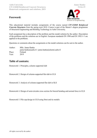
Homework 5, Design for biaxial bending and normal force in ULS 1(2)
Return to MyCourses in PDF-format.
Goal of the assignment is to check is the resistance of the given cross section (figure 1) and reinforcement adequate
against biaxial bending and normal force. Cross section is affected by eccentric normal force.
- Column concrete class: C50/60, semi-circular column
- Reinforcement fyk=500MPa, 24pcs of 32mm diameter bars placed according to FIG 1.
- Loads affecting the column: Normal force NEd=13100kN
Eccentricities: eX = 100mm, eY=400mm *
*Note: imperfections and 2nd
order effects has already been considered in the given
loads
a) Calculate the effects of action in ultimate limit state around (X-X) and (Y-Y)-axis: MEd.X and MEd.Y
b) Calculate the simplified N-M interaction (capacity) diagram of the cross section about (X-X) axis. Use at least 3
points for the interaction diagrams:
1. Pure tensile failure: Tensile strain of ɛs=1% in top and bottom reinforcement.
2. Balanced failure: Tensile strain of ɛs=fyd/Es in bottom reinforcement and ultimate compressive strain
ɛc=-0,35% in top of concrete section.
4. Pure compression failure: Uniform strain of ɛc=-0,20% in bottom and top of section.
c) Calculate the simplified N-M interaction (capacity) diagram of the cross section about (Y-Y) axis.
d) Place the calculated effects of action from (a) to the N-M interaction diagram calculated in (b). Determine the
bending moment capacity of the cross section MRd.X and MRd.Y
e) Check the capacity of the cross section against bi-axial bending using to EC2 equation (5.39)
f) Is the capacity of the cross section adequate against biaxial bending and normal force? If not, how could it be
improved?
Figure 1. Cross section and side view of the column
8. Aalto University Janne Hanka
CIV-E4040 Reinforced Concrete Structures 2019 20.1.2019
Homework 5, Design for biaxial bending and normal force in ULS 2(2)
Return to MyCourses in PDF-format.
Tip: Simplified N-M interaction diagram of the cross section can be calculated using the following strain
distributions of the cross section according (refer to EC2 figure 6.1):
1. Pure tensile failure: Tensile strain of ɛs=1% in top and bottom reinforcement.
2. Balanced failure: Tensile strain of ɛs=fyk/Es in bottom reinforcement
and ultimate compressive strain ɛc=-0,35% at the top of concrete section.
3. Ultimate compressive strain ɛc=-0,35% at the top of concrete section and compressive strain of ɛc=-0,20% at
the centroid of the cross section.
4. Pure compression failure: Uniform strain of ɛc=-0,20% in bottom and top of cross section.
Tip c: How to evaluate bending moment capacity MRd for the given normal force NEd from the N-M diagram:
Tip (d): Resistance of the cross section against biaxial bending and normal force can be checked using the
following criterion: [EN 1992-1-1 5.8.9(4) equation (5.39)]
1
.
.
.
.
a
zRd
zEd
a
yRd
yEd
M
M
M
M
MEd z/y = design moment around the respective axis
MRd z/y = moment resistance in the respective direction
a = exponent for rectangular cross sections with linear interpolation for intermediate values:
NEd/NRd = 0,1 0,7 1,0
a = 1,0 1,5 2,0
NEd = design value of axial force
NRd = Acfcd + Asfyd, is the design axial resistance of section.
Ac = area of the concrete section As = area of longitudinal reinforcement
Tip: Design bending moment and moments due to imperfection and second order effects can be estimated with
the following equations (According to RakMK B4 §2.2.5.4)* :
Design bending moment: MEd = MEd.0 + Mi + M2
Moment due to actions (hor. force etc) MEd.0
Moment due to imperfections Mi = D/20 + L0/500
Moment due to 2nd
order effects M2 = (λ/145)2
D*NEd
NEd = Design normal force
D = Diameter of circular column or height of rectangular column
L0 = L*μ = Buckling length of column
λ = 4L0/D = Slenderness ratio for circular columns
λ = 3,464*L0/D = Slenderness ratio for rectangular columns
μ = Buckling factor. μ=2 for mast columns. μ=1 for braced columns
* RakMK method can be used in exercise because, EC2 calculation method for 2nd order effects is rather cumbersome. RakMK is yields generally
more conservative results, thus the design on the safe side. Detailed design method acc. to EC2 has been shown in:
http://www.elementtisuunnittelu.fi/fi/runkorakenteet/pilarit/nurjahduspituus
http://eurocodes.fi/1992/paasivu1992/sahkoinen1992/Leaflet_5_Pilarit.pdf
9. Aalto University Janne Hanka
CIV-E4040 Reinforced Concrete Structures 2019 27.1.2019
Homework 5, Strut and tie design of pilecap 1(2)
Return to MyCourses in PDF-format.
You are designing a pilecap foundation. Goal of the task is to form a strut-and-tie model of the structure and
calculate the required rebar.
-Concrete strength at final condition: C30/37 Consequence class CC2
-Rebar fyk=500MPa, Es=200GPa
-Design load in ULS: NEd=3000kN
-Minimum concrete cover to rebar is c=40mm
-Foundation dimensions: L1=L3=500mm ; L2=1400mm ; L4=1400mm ; H=900mm
a=100mm (embedment depth of piles)
D=400mm (diameter of the column on top of the foundation)
-Rectangular piles: Dimensions: 400x400. Length of piles=20m. Concrete used in the piles is C30/37
a) Form the strut-and-tie model of the pile-cap foundation.
b) Calculate the design forces in the struts and ties.
c) Calculate the required amounts of reinforcements in the tensile struts.
d) Check is the allowable compressive stress in concrete exceeded in any struts?
e) Choose the actual amount of reinforcements and place them to the structure. Draw a drawing of the structure
with the reinforcement. Pay attention to detailing and anchoring of tensile struts!
Figure 1. Pland and section of the pile-cap-foundation. 1=Pile. 2=Pilecap foundation. 3=Column above
10. Aalto University Janne Hanka
CIV-E4040 Reinforced Concrete Structures 2019 27.1.2019
Homework 5, Strut and tie design of pilecap 2(2)
Return to MyCourses in PDF-format.
Tips regarding strut-and-ties in EC2:
Allowable stress for a concrete strut may be calculated using equation:
σRd.max = fcd (with compressive transverse stress or without transverse stress, EC2 fig.6.23)
σRd.max= 0,6 (1 – fck/250) fcd (with tensile transverse stress, EC2 fig.6.23)
Allowable stress for a node may be calculated using equation:
σRd.max = k v’ fcd where:
k= 1 (compression node without tensile ties, EC2 fig.6.26)
k=0,85 (compression-tension node with reinforcement from one direction, EC2 fig.6.27)
k=0,75 (compression-tension node with reinforcement provided in two directions, EC2 fig.6.28)
Figure 6.26: Compression node
without ties.
Figure 6.27: Compression tension
node with reinforcement provided
in one direction.
Figure 6.28: Compression
tension node with
reinforcement provided in
two directions.