This document compares the economical aspects of long span flat slabs and grid slabs. Flat slabs are modeled using the direct design method, while grid slabs are modeled using plate theory. The cost is calculated based on the quantity of steel, concrete volume, and formwork costs. For spans ranging from 5-13 meters, the cost per square meter is determined for different slab designs. The results show that flat slabs are more economical for smaller spans, but grid slabs become more economical for longer spans above 9 meters.

![III. GRID SLAB
A. Analysis of Grid Floors
Analysis of grid floors can be carried out by three different
methods which are
Approximate methods
Plate theory method
Stiffness matrix method using computer
In present work the analysis and design of grid slab is
carried by plate theory method. Different span slab form are
selected and designed for span ranging from 5 to 13 meters.
Total 5 slab forms are designed with span 5X5, 7x7, 9x9,
11x11, and 13x13 m
B. Atomization of Design.
For the analysis and design procedure excel worksheet are
prepared. In this work sheet only certain essential data are to
be supplied and all the calculations are done on its own.
In the worksheet red colour text denotes the data to be
supplied and blue colour text denotes the results through
calculations.
Input data at the starting of the excel worksheet are as
under
1. Length of beam Lx, Ly (m)
2. Number of beams Nx, Ny (No’s)
3. Spacing of ribs (m)
4. Depth of beam (mm)
5. Width of beam (mm)
6. Width of flange (mm)
7. Grade of concrete and steel (N/mm2
)
8. Dead load (kN/m2
)
9. Live load (kN/m2
)
10. Floor finish (kN/m2
)
From the above supplied data we will get the total dead
load of slab, beams in X and Y direction from this load per
square meter is calculated. The following are the output
parameters which are obtained using developed excel sheet.
1. Moment of inertia (mm4
)
2. Flexural rigidity of ribs
3. Modulus of shear (kN/m2
)
4. Torsional constants (cu-m)
5. Torsional rigidity
6. Central deflection check (mm)
7. Long term deflection (mm)
8. Span/deflection (mm)
9. Maximum bending moments (kN.m)
10. Maximum torsional moments (kN.m)
11. Shear forces (kN)
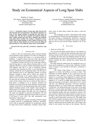
The design of slab is carried out to satisfy strength and
serviceability criteria. The quantity assessment is carried out
for designed slab and rate analysis is performed. Cost in terms
of per meter2
are derived of various slab forms for span
ranging from 5 to 13 m as per table 2
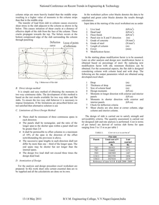
TABLE II. COST OF GRID SLAB PER M
2
Fig. 2 Cost comparison of flat and grid slab
IV. CONCLUSIONS
From the graph of costing, it can be concluded that
1. In flat slab as the span range increases, there is steady
increase in the unit cost.
2. In grid slab as the span range increases, the increase in
the unit cost is not significant.
3. Flat slab with smaller spans are proved to be economical
but as the span range increases the grid slab becomes
economical
4. Thus Grid slab is proved to be more economical for long
span slab in comparison to Flat slab
REFERENCES
[1] N. Krishnaraju., “Advanced Reinforced Concrete Design” S.I.Units
[2] H.J. Shah., “Reinforced concrete Vol II”.
[3] S.N. Sinha., “Reinforced concrete Design”.
[4] V.P. Lunjha., “Computer Aided Analysis Design and drafting of R.C.C
Flat Slab”, -Thesis.
[5] IS : 456 – 2000 “Plain And Reinforced Concrete - Code Of Practice” (
Fourth Revision )
[6] SP- 16., “Design Aids for Reinforced Concrete to IS : 456 – 1978”
[7] SOR : 2008-09, “R&B Department, Govt of Gujarat”
Grid slab
Panels Total cost of 9
panels
Unit
cost/m2
Rs Rs
5 X 5 339744 1510
7 X 7 683518 1550
10 X 10 1143353 1568
11 X 11 1742564 1600
13 X 13 2579744 1696
Reference of rates S.O.R .R &B 2008 -2009
13-14 May 2011 B.V.M. Engineering College, V.V.Nagar,Gujarat,India
National Conference on Recent Trends in Engineering & Technology](https://image.slidesharecdn.com/101079-slab-150601063604-lva1-app6891/85/slab-3-320.jpg)