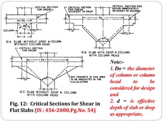
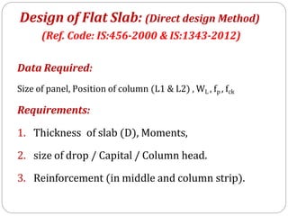
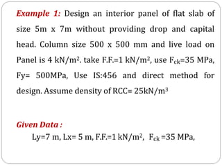
1. The panel size is 5m x 7m without drop or column head.
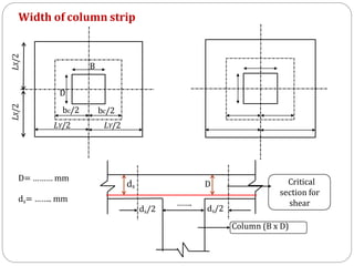
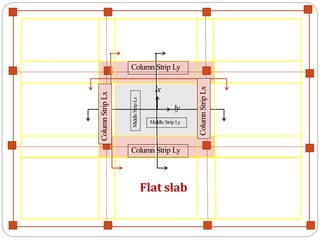
2. The width of the column strip is calculated as 0.25x7m = 1.75m on each side of the column.
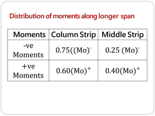
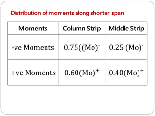
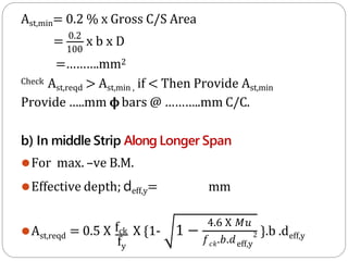
3. The required reinforcement is calculated for bending moments in the column strip and middle strip along the longer and shorter spans based on the loading and design parameters. The reinforcement details are shown in diagrams.

![Clause. No.:- 31.1.1 pg. 53 [IS:456-2000]
For the purpose of this clause, the following definitions shall apply:
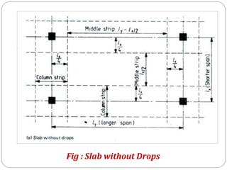
a) Column strip:- Column strip means a design strip
having a width = 0.25 l2 ,but It should not be
greater than 0.25 l1 on each side of the column
centre line,
Where,
l1, - Span in the direction moments are being
determined (measured centre to centre of supports).
l2 - Span transverse to l1,
(measured centre to centre of supports).](https://image.slidesharecdn.com/dacsunit-3-rccflatslabarp-240130052356-9495e5e3/85/DACS_UNIT-3-RCC-Flat-slab-ARP-pptx-10-320.jpg)
![1] Width of column strip (Along longer span):
(Cl. No. 31.1.1, P.No.53, IS 456-2000)
Width of column strip (2 bc)
bc = Width on either side of Column centre line
= 0.25L1 or 0.25 L2 which ever is less
⚫Width of column strip = 2bc
⚫Width of middle strip along longer span = L1-2bc
⚫Width of middle strip along shorter span =L2-2bc](https://image.slidesharecdn.com/dacsunit-3-rccflatslabarp-240130052356-9495e5e3/85/DACS_UNIT-3-RCC-Flat-slab-ARP-pptx-21-320.jpg)
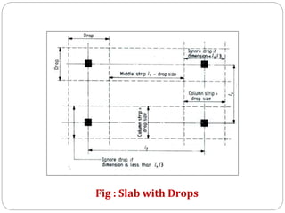
![2] Thickness of slab (D) : Cl. No. 31.2.1 P.No. 53
a) If Drop is not provided to slab
D = ≥ 125 mm
b) If Drop is provided
D = ≥ 125 mm](https://image.slidesharecdn.com/dacsunit-3-rccflatslabarp-240130052356-9495e5e3/85/DACS_UNIT-3-RCC-Flat-slab-ARP-pptx-22-320.jpg)
![3] Size of Drop (Cl. No.31.2.1 Pg.No.53)
⚫Size of Drop = (For interior panel)
⚫Size of Drop = (For exterior panel)
⚫Thickness of drop = (D = thickness of slab)](https://image.slidesharecdn.com/dacsunit-3-rccflatslabarp-240130052356-9495e5e3/85/DACS_UNIT-3-RCC-Flat-slab-ARP-pptx-23-320.jpg)
![4] Size of column heador Capital
(cl. No.31.2.1 Pg. No.53, 54, fig. no. 12)
⚫Diameter of column head =
⚫Where ,
L - Average span length in mm.](https://image.slidesharecdn.com/dacsunit-3-rccflatslabarp-240130052356-9495e5e3/85/DACS_UNIT-3-RCC-Flat-slab-ARP-pptx-24-320.jpg)
![5] Load on Slab:-
⚫D.L. = Wd = 25 x D
F.F.L = Wf = Assume 1 to 2 kN/m2 if not given
L.L. = WL = Given ORAs per the IS: 875 Part-II
Total Load = WT
Design Load = Wu = 1.5 WT](https://image.slidesharecdn.com/dacsunit-3-rccflatslabarp-240130052356-9495e5e3/85/DACS_UNIT-3-RCC-Flat-slab-ARP-pptx-25-320.jpg)
![6] Tofind BendingMoment:
A) Along longer span (take L1 = Ly, L2 =Lx)
⚫Clear span = (Ln) = L1 – Dc > 0.64 L1
⚫Load on Panel =(Wo) = Wu.Ln.L2
⚫Total moment = Mo = kN.m
⚫Total - ve moment = (Mo)- =0.65 (Mo)
⚫Total + ve moment = (Mo)+ = 0.35(Mo)](https://image.slidesharecdn.com/dacsunit-3-rccflatslabarp-240130052356-9495e5e3/85/DACS_UNIT-3-RCC-Flat-slab-ARP-pptx-26-320.jpg)
![6] Tofind bending Moment
B) Along shorter span (L1 = Lx, L2 =Ly)
⚫Clear span = (Ln) = L1 – Dc > 0.64 L1
⚫ Load on Panel =(Wo) = Wu.Ln.L2
⚫Total moment = Mo = kNm/m width
-
⚫Total -ve moment = (Mo) = 0.65 (Mo)
+
⚫Total + ve moment = (Mo) = 0.35(Mo)](https://image.slidesharecdn.com/dacsunit-3-rccflatslabarp-240130052356-9495e5e3/85/DACS_UNIT-3-RCC-Flat-slab-ARP-pptx-28-320.jpg)
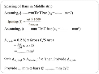
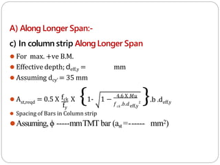
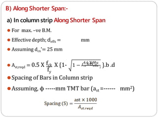
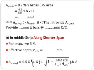
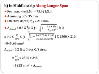
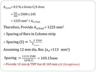
![7] Design of Reinforcement
A) Along Longer Span:-
a) In column strip Along Longer Span
⚫ For max. –ve B.M.
mm
⚫ Effective depth; deff,y =
⚫ Assuming dcy’ = 35 mm
st,reqd
fy
4.6 X 𝑀𝑢
𝑐𝑘
𝑓 .𝑏.𝑑eff,y
2
⚫ A = 0.5 X fck X {1- 1 − }.b .deff,y
⚫ Spacing of Bars in Column strip
⚫Assuming,ϕ -----mmTMT bar (ast =------ mm2)](https://image.slidesharecdn.com/dacsunit-3-rccflatslabarp-240130052356-9495e5e3/85/DACS_UNIT-3-RCC-Flat-slab-ARP-pptx-30-320.jpg)
![8] Reinforcement details:
Fig : Slab without Drops](https://image.slidesharecdn.com/dacsunit-3-rccflatslabarp-240130052356-9495e5e3/85/DACS_UNIT-3-RCC-Flat-slab-ARP-pptx-36-320.jpg)
![12] Details of Main & SecondaryReinforcement in Columnstrip
Reinf. details along
short span (direction) c
Span= Lx = ……. m
Span= Ly = ………… m
Reinf. details along
Long span (direction)
Provide …….mm dia. bar @......mm C/C at top in both
Directions as non-tension reinforcement. (straight)
Ds=…….mm
Ds=…….mm
dey=…….mm
dex=…….mm
c
Provide …….mm dia. bar @......mm C/C at top in both
Directions as non-tension reinforcement. (straight)
Provide …….mm dia. Alt. Bent up bar @......mm C/C in column strip.
Provide …….mm dia. Alt. Bent up bar @......mm C/C in column strip.](https://image.slidesharecdn.com/dacsunit-3-rccflatslabarp-240130052356-9495e5e3/85/DACS_UNIT-3-RCC-Flat-slab-ARP-pptx-39-320.jpg)
![12] Details of Main & Secondary Reinforcement in Middlestrip
Reinf. details along
short span (direction) c
Span= Lx = ……. m
Span= Ly = ………… m
Reinf. details along
Long span (direction)
Provide …….mm dia. bar @......mm C/C at top in both
Directions as non-tension reinforcement. (straight)
Ds=…….mm
Ds=…….mm
dey=…….mm
dex=…….mm
c
Provide …….mm dia. bar @......mm C/C at top in both
Directions as non-tension reinforcement. (straight)
Provide …….mm dia. Alt. Bent up bar @......mm C/C in Middle strip.
Provide …….mm dia. Alt. Bent up bar @......mm C/C in Middle strip.](https://image.slidesharecdn.com/dacsunit-3-rccflatslabarp-240130052356-9495e5e3/85/DACS_UNIT-3-RCC-Flat-slab-ARP-pptx-40-320.jpg)
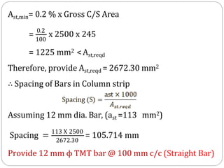
![1] Thickness of slab (D) : (Cl. No.31.2.1 Pg. No.53)
a) If Drop is not provided then
D = ≥ 125 mm
Say, D= 245 mm
Assuming effective cover = 35 mm
Therefore, effective depth of slab(d);
d = 245 – 35=210 mm](https://image.slidesharecdn.com/dacsunit-3-rccflatslabarp-240130052356-9495e5e3/85/DACS_UNIT-3-RCC-Flat-slab-ARP-pptx-42-320.jpg)
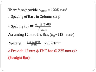
![Say, bc = Width on either side of Column centre line
bc = 0.25L1 or 0.25 L2 which ever is less
bc = 0.25 x L1 = 0.25 x 7 = 1.75 m
OR
bc =0.25 x L2 = 0.25 x 5 = 1.25 m
Provide bc = 1.25 m
Total Width of column strip = 2bc = 2 x 1.25 =2.5 m
Width of middle strip along longer span = L1- 2bc = 7-2x1.25 = 4.5 m
Width of middle strip along shorter span =L2- 2bc = 5-2x1.25= 2.5 m
2] Width of column strip (2bc) (Along longer span):
(Cl. No. 31.1.1, P.No.53, IS 456-2000)](https://image.slidesharecdn.com/dacsunit-3-rccflatslabarp-240130052356-9495e5e3/85/DACS_UNIT-3-RCC-Flat-slab-ARP-pptx-43-320.jpg)
![3] Load calculations:-
i) D.L. = 0.245 x 24 = 5.88 kN/m2
ii) L.L. =
iii) F.F. =
= 4.00 kN/m2
= 1.00 kN/m2
WT = 10.88 kN/m2
Therefore, Ultimate load = 1.5 x WT = 16.32 kN/m2
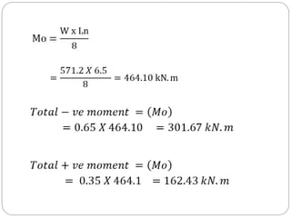
4] To Find B.M.(maxi)
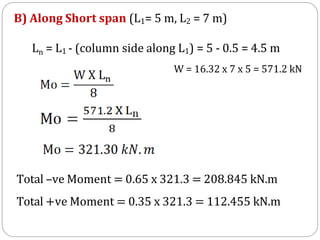
A) Along long span (L1= 7 m, L2 = 5 m)
Ln = L1 – (column side along L1) = 7- 0.5 = 6.5 m
Total design moment Mo =
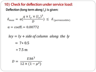
W = 16.32 x 7 x 5 = 571.2 kN](https://image.slidesharecdn.com/dacsunit-3-rccflatslabarp-240130052356-9495e5e3/85/DACS_UNIT-3-RCC-Flat-slab-ARP-pptx-44-320.jpg)
![5] Distribution of Moments:- (Along long span )
Moments Column Strip Middle Strip
-ve Moments
= 0.75 x (Mo) -
= 0.75 x 301.67
= 226.25 kN.m
= 0.25 x (Mo) -
= 0.25 x 301.67
= 75.42 kN.m
+ve Moments
=0.60 x (Mo)+
=0.60 x 162.43
= 97.46 kN.m
=0.40 x (Mo)+
=0.40 x 162.43
= 64.97 kN.m](https://image.slidesharecdn.com/dacsunit-3-rccflatslabarp-240130052356-9495e5e3/85/DACS_UNIT-3-RCC-Flat-slab-ARP-pptx-46-320.jpg)
![Moments Column Strip Middle Strip
-ve Moments
= 0.75 x (Mo) -
= 0.75 x 208.845
= 156.63 kN.m
= 0.25 x (Mo) -
= 0.25 x 208.845
= 52.211 kN.m
+ve Moments
=0.60 x (Mo)+
=0.60 x 112
= 67.20 kN.m
=0.40 x (Mo)+
=0.40 x 112
= 44.80 kN.m
6] Distribution of Moments:- Along short span](https://image.slidesharecdn.com/dacsunit-3-rccflatslabarp-240130052356-9495e5e3/85/DACS_UNIT-3-RCC-Flat-slab-ARP-pptx-48-320.jpg)
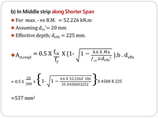
![7] Design of Reinforcement
A) Along Longer Span:-
a) In column strip Along Longer Span
⚫ For max. –ve B.M. = 226.25 kN.m
⚫ Assuming dcy’= 35 mm
⚫ Effective depth; dyeff = 210 mm.
st,reqd
fy
⚫ A = 0.5 X fck X {1- 1 −
4.6 X 𝑀𝑢
𝑐𝑘
𝑓 .𝑏.dyeff
2
}.b .dyeff
= 0.5 X
35
500
x {1- 1 −
4.6 X 226.25 𝑋 106
35 𝑋2500𝑋2102
}X 2500 X 210
=2672.30mm2](https://image.slidesharecdn.com/dacsunit-3-rccflatslabarp-240130052356-9495e5e3/85/DACS_UNIT-3-RCC-Flat-slab-ARP-pptx-49-320.jpg)


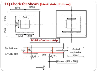
![Shear resistance = load from slab to column
(Shear stress x shear area) = (load x shaded area)
1480x [4 x (0.5 + ds) x ds] =16.32 x [(7x5)-(0.5+ds)2]
1480x[4 x (0.5ds + ds2)]=16.32 x [35-(0.25+1ds+ds2)]
5936.32 ds2+2976.32ds-567.12=0
ds=0.147 m = 147 mm < dprovided =210 mm
Therefore, section is safe in shear.](https://image.slidesharecdn.com/dacsunit-3-rccflatslabarp-240130052356-9495e5e3/85/DACS_UNIT-3-RCC-Flat-slab-ARP-pptx-71-320.jpg)
![12] Reinforcement Detailing :
layout of column and middle strips](https://image.slidesharecdn.com/dacsunit-3-rccflatslabarp-240130052356-9495e5e3/85/DACS_UNIT-3-RCC-Flat-slab-ARP-pptx-72-320.jpg)
![12 A] Details of Main & SecondaryReinforcement in Columnstrip
Reinf. details along
short span (direction) c
Span= Lx = ……. m
Span= Ly = ………… m
Reinf. details along
Long span (direction)
Provide …….mm dia. bar @......mm C/C at top in both
Directions as non-tension reinforcement. (straight)
Ds=…….mm
Ds=…….mm
dey=…….mm
dex=…….mm
c
Provide …….mm dia. bar @......mm C/C at top in both
Directions as non-tension reinforcement. (straight)
Provide …….mm dia. Alt. Bent up bar @......mm C/C in column strip.
Provide …….mm dia. Alt. Bent up bar @......mm C/C in column strip.](https://image.slidesharecdn.com/dacsunit-3-rccflatslabarp-240130052356-9495e5e3/85/DACS_UNIT-3-RCC-Flat-slab-ARP-pptx-74-320.jpg)
![12 B] Details of Main & SecondaryReinforcement in Middlestrip
Reinf. details along
short span (direction) c
Span= Lx = ……. m
Span= Ly = ………… m
Reinf. details along
Long span (direction)
Provide …….mm dia. bar @......mm C/C at top in both
Directions as non-tension reinforcement. (straight)
Ds=…….mm
Ds=…….mm
dey=…….mm
dex=…….mm
c
Provide …….mm dia. bar @......mm C/C at top in both
Directions as non-tension reinforcement. (straight)
Provide …….mm dia. Alt. Bent up bar @......mm C/C in Middle strip.
Provide …….mm dia. Alt. Bent up bar @......mm C/C in Middle strip.](https://image.slidesharecdn.com/dacsunit-3-rccflatslabarp-240130052356-9495e5e3/85/DACS_UNIT-3-RCC-Flat-slab-ARP-pptx-75-320.jpg)