This document summarizes the key aspects of flat slab construction and design according to Indian code IS 456-2000. It defines flat slabs as slabs that are directly supported by columns without beams, and describes four common types based on whether drops and column heads are used. The main topics covered include guidelines for proportioning slabs and drops, methods for determining bending moments and shear forces, requirements for slab reinforcement, and an example problem demonstrating the design of an interior flat slab panel.
DESIGN AND ANALYSIS OF G+3 RESIDENTIAL BUILDING BY S.MAHAMMAD FROM RAJIV GAND...Mahammad2251
Structural design is the primary aspect of civil engineering. The foremost basic in
structural engineering is the design of simple basic components and members of a building viz., Slabs,
Beams, Columns and Footings. In order to design them, it is important to first obtain the plan of the
particular building. Thereby depending on the suitability; plan layout of beams and the position of
columns are fixed.
information on types of beams, different methods to calculate beam stress, design for shear, analysis for SRB flexure, design for flexure, Design procedure for doubly reinforced beam,
Design of water tank (RCC design) By Working Stress Method as per Indian Standards.
Useful for Practicing Civil Engineers & Students of B.Tech & B.E in civil
This resource material is exclusively for the purpose of knowledge dissemination for the use of Civil engineering Fraternity, professionals & students.
This file contains state of art techniques adopted & practiced as per IS456 code provisions for analysis design & detailing of flat slab structural systems.
The presentation aims to provide clear,concise, technical details of flat slabs design.
The presentation deals with structural actions & behavior of flat slabs with visual representations obtained through finite element analysis.
The knowledge gained can be used for designing building structures frequently encountered in construction.
The presentation covers an important feature of slab systems supported on rigid & flexible support & clearly demarcates the minimum beam dimensions required to consider the supports to be either rigid or flexible.
The presentation alsoincludes clear technical drawings to highlight the importance of detailing w.r.t. rebar lay out - positioning & curtailment. Typical section drawing through middle & column strips are also included for visualizing rebar patterns in 3 -d views.
This presentation is an outcome of series of lectures for undergrad & grad students studying in civil engineering.
My next presentation would be on Analysis & design of deep beams.
Kindly mail me ( vvietcivil@gmail.com) your questions & valuable feedback.
Growing of Precast construction system has given emphasis on improving work zone safety, reducing construction time and environmental impact, while maintaining the quality. The connections are the most important part of precast construction systems, being the general behavior of the precast structures related to their design, construction and performance. In this civil engineering project a trial to compare the strength of three types of portal frames viz. Monolithic Portal Frame, Portal Frame with corbel and Portal Frame without corbel and their deflections at various loads were observed and derived conclusion which one is efficient among all frames designed and cast.
A hollow core slab refers to a precast slab that is prepared using prestressed concrete. It is generally used in the construction of floors for high-rise apartments or multistorey buildings.
Welcome to WIPAC Monthly the magazine brought to you by the LinkedIn Group Water Industry Process Automation & Control.
In this month's edition, along with this month's industry news to celebrate the 13 years since the group was created we have articles including
A case study of the used of Advanced Process Control at the Wastewater Treatment works at Lleida in Spain
A look back on an article on smart wastewater networks in order to see how the industry has measured up in the interim around the adoption of Digital Transformation in the Water Industry.
Automobile Management System Project Report.pdfKamal Acharya
The proposed project is developed to manage the automobile in the automobile dealer company. The main module in this project is login, automobile management, customer management, sales, complaints and reports. The first module is the login. The automobile showroom owner should login to the project for usage. The username and password are verified and if it is correct, next form opens. If the username and password are not correct, it shows the error message.
When a customer search for a automobile, if the automobile is available, they will be taken to a page that shows the details of the automobile including automobile name, automobile ID, quantity, price etc. “Automobile Management System” is useful for maintaining automobiles, customers effectively and hence helps for establishing good relation between customer and automobile organization. It contains various customized modules for effectively maintaining automobiles and stock information accurately and safely.
When the automobile is sold to the customer, stock will be reduced automatically. When a new purchase is made, stock will be increased automatically. While selecting automobiles for sale, the proposed software will automatically check for total number of available stock of that particular item, if the total stock of that particular item is less than 5, software will notify the user to purchase the particular item.
Also when the user tries to sale items which are not in stock, the system will prompt the user that the stock is not enough. Customers of this system can search for a automobile; can purchase a automobile easily by selecting fast. On the other hand the stock of automobiles can be maintained perfectly by the automobile shop manager overcoming the drawbacks of existing system.
Event Management System Vb Net Project Report.pdfKamal Acharya
In present era, the scopes of information technology growing with a very fast .We do not see any are untouched from this industry. The scope of information technology has become wider includes: Business and industry. Household Business, Communication, Education, Entertainment, Science, Medicine, Engineering, Distance Learning, Weather Forecasting. Carrier Searching and so on.
My project named “Event Management System” is software that store and maintained all events coordinated in college. It also helpful to print related reports. My project will help to record the events coordinated by faculties with their Name, Event subject, date & details in an efficient & effective ways.
In my system we have to make a system by which a user can record all events coordinated by a particular faculty. In our proposed system some more featured are added which differs it from the existing system such as security.
About
Indigenized remote control interface card suitable for MAFI system CCR equipment. Compatible for IDM8000 CCR. Backplane mounted serial and TCP/Ethernet communication module for CCR remote access. IDM 8000 CCR remote control on serial and TCP protocol.
• Remote control: Parallel or serial interface.
• Compatible with MAFI CCR system.
• Compatible with IDM8000 CCR.
• Compatible with Backplane mount serial communication.
• Compatible with commercial and Defence aviation CCR system.
• Remote control system for accessing CCR and allied system over serial or TCP.
• Indigenized local Support/presence in India.
• Easy in configuration using DIP switches.
Technical Specifications
Indigenized remote control interface card suitable for MAFI system CCR equipment. Compatible for IDM8000 CCR. Backplane mounted serial and TCP/Ethernet communication module for CCR remote access. IDM 8000 CCR remote control on serial and TCP protocol.
Key Features
Indigenized remote control interface card suitable for MAFI system CCR equipment. Compatible for IDM8000 CCR. Backplane mounted serial and TCP/Ethernet communication module for CCR remote access. IDM 8000 CCR remote control on serial and TCP protocol.
• Remote control: Parallel or serial interface
• Compatible with MAFI CCR system
• Copatiable with IDM8000 CCR
• Compatible with Backplane mount serial communication.
• Compatible with commercial and Defence aviation CCR system.
• Remote control system for accessing CCR and allied system over serial or TCP.
• Indigenized local Support/presence in India.
Application
• Remote control: Parallel or serial interface.
• Compatible with MAFI CCR system.
• Compatible with IDM8000 CCR.
• Compatible with Backplane mount serial communication.
• Compatible with commercial and Defence aviation CCR system.
• Remote control system for accessing CCR and allied system over serial or TCP.
• Indigenized local Support/presence in India.
• Easy in configuration using DIP switches.
Courier management system project report.pdfKamal Acharya
It is now-a-days very important for the people to send or receive articles like imported furniture, electronic items, gifts, business goods and the like. People depend vastly on different transport systems which mostly use the manual way of receiving and delivering the articles. There is no way to track the articles till they are received and there is no way to let the customer know what happened in transit, once he booked some articles. In such a situation, we need a system which completely computerizes the cargo activities including time to time tracking of the articles sent. This need is fulfilled by Courier Management System software which is online software for the cargo management people that enables them to receive the goods from a source and send them to a required destination and track their status from time to time.
Forklift Classes Overview by Intella PartsIntella Parts
Discover the different forklift classes and their specific applications. Learn how to choose the right forklift for your needs to ensure safety, efficiency, and compliance in your operations.
For more technical information, visit our website https://intellaparts.com
Cosmetic shop management system project report.pdfKamal Acharya
Buying new cosmetic products is difficult. It can even be scary for those who have sensitive skin and are prone to skin trouble. The information needed to alleviate this problem is on the back of each product, but it's thought to interpret those ingredient lists unless you have a background in chemistry.
Instead of buying and hoping for the best, we can use data science to help us predict which products may be good fits for us. It includes various function programs to do the above mentioned tasks.
Data file handling has been effectively used in the program.
The automated cosmetic shop management system should deal with the automation of general workflow and administration process of the shop. The main processes of the system focus on customer's request where the system is able to search the most appropriate products and deliver it to the customers. It should help the employees to quickly identify the list of cosmetic product that have reached the minimum quantity and also keep a track of expired date for each cosmetic product. It should help the employees to find the rack number in which the product is placed.It is also Faster and more efficient way.
Hybrid optimization of pumped hydro system and solar- Engr. Abdul-Azeez.pdffxintegritypublishin
Advancements in technology unveil a myriad of electrical and electronic breakthroughs geared towards efficiently harnessing limited resources to meet human energy demands. The optimization of hybrid solar PV panels and pumped hydro energy supply systems plays a pivotal role in utilizing natural resources effectively. This initiative not only benefits humanity but also fosters environmental sustainability. The study investigated the design optimization of these hybrid systems, focusing on understanding solar radiation patterns, identifying geographical influences on solar radiation, formulating a mathematical model for system optimization, and determining the optimal configuration of PV panels and pumped hydro storage. Through a comparative analysis approach and eight weeks of data collection, the study addressed key research questions related to solar radiation patterns and optimal system design. The findings highlighted regions with heightened solar radiation levels, showcasing substantial potential for power generation and emphasizing the system's efficiency. Optimizing system design significantly boosted power generation, promoted renewable energy utilization, and enhanced energy storage capacity. The study underscored the benefits of optimizing hybrid solar PV panels and pumped hydro energy supply systems for sustainable energy usage. Optimizing the design of solar PV panels and pumped hydro energy supply systems as examined across diverse climatic conditions in a developing country, not only enhances power generation but also improves the integration of renewable energy sources and boosts energy storage capacities, particularly beneficial for less economically prosperous regions. Additionally, the study provides valuable insights for advancing energy research in economically viable areas. Recommendations included conducting site-specific assessments, utilizing advanced modeling tools, implementing regular maintenance protocols, and enhancing communication among system components.
Hybrid optimization of pumped hydro system and solar- Engr. Abdul-Azeez.pdf
DESIGN OF FLAT SLABS
1. 1.1 INTRODUCTION
Common practice of design and construction is to support the slabs by beams and support the beams
by columns. This may be called as beam-slab construction. The beams reduce the available net clear
ceiling height. Hence in warehouses, offices and public halls some times beams are avoided and slabs
are directly supported by columns. This types of construction is aesthetically appealing also. These
slabs which are directly supported by columns are called Flat Slabs. Fig. 1.1 shows a typical flat slab.
d
2
Critical section for shear
Fig. 1.1 A typical flat slab (without drop and column head)
The column head is some times widened so as to reduce the punching shear in the slab. The
widened portions are called column heads. The column heads may be provided with any angle from
the consideration of architecture but for the design, concrete in the portion at 45º on either side of
vertical only is considered as effective for the design [Ref. Fig. 1.2].
d
2
Critical section for shear
Concrete in this area is
neglected for calculation
90°
Fig. 1.2 Slab without drop and column with column head
1
Flat Slabs
CHAPTER
2. 2 Advanced R.C.C. Design
Moments in the slabs are more near the column. Hence the slab is thickened near the columns by
providing the drops as shown in Fig. 1.3. Sometimes the drops are called as capital of the column.
Thus we have the following types of flat slabs:
Critical section for shear
d
2
d
2
Critical section
for shear
Fig. 1.3 Slab with drop and column without column head
(i) Slabs without drop and column head (Fig. 1.1).
(ii) Slabs without drop and column with column head (Fig. 1.2).
(iii) Slabs with drop and column without column head (Fig. 1.3).
(iv) Slabs with drop and column head as shown in Fig. 1.4.
Critical section
for shear
45° 45°
d
2
Fig. 1.4 Slab with drop and column with column head
The portion of flat slab that is bound on each of its four sides by centre lines of adjacent columns is
called a panel. The panel shown in Fig. 1.5 has size L1 ´ L2. A panel may be divided into column strips
and middle strips. Column Strip means a design strip having a width of 0.25L1 or 0.25L2,
whichever is less. The remaining middle portion which is bound by the column strips is called middle
strip. Fig. 1.5 shows the division of flat slab panel into column and middle strips in the direction y.
3. Flat Slabs 3
L2a L2b
C of panel A C of panel B
Middle stripMiddle strip
Column strip
L2a
4
L2b
4
Column strip Column strip
y
xo
L1
but
L
< 1
4
but
L
< 1
4
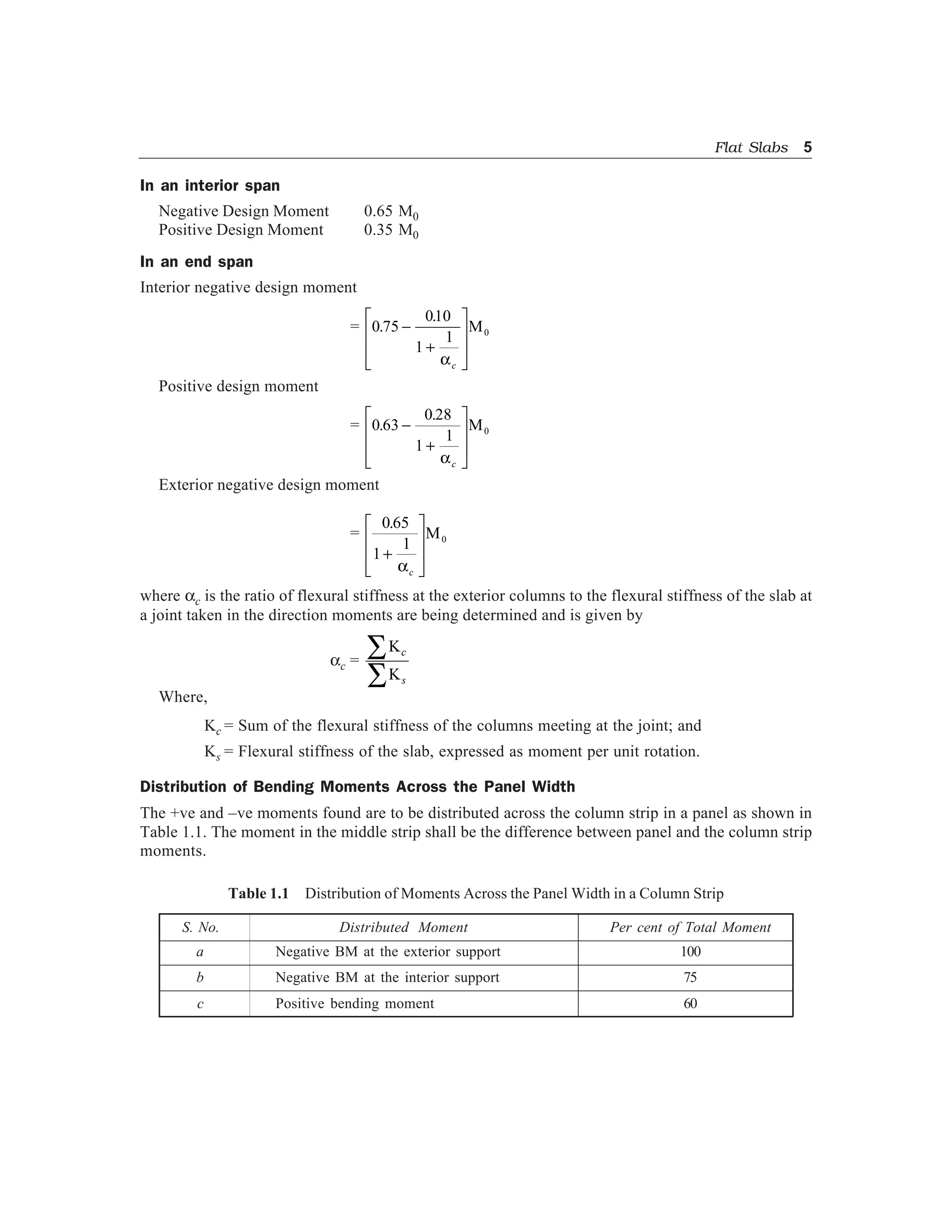
Fig. 1.5 Panels, column strips and middle strips is y-direction
1.2 PROPORTIONING OF FLAT SLABS
IS 456-2000 [Clause 31.2] gives the following guidelines for proportioning.
1.2.1 Drops
The drops when provided shall be rectangular in plan, and have a length in each direction not less than
one third of the panel in that direction. For exterior panels, the width of drops at right angles to the non
continuous edge and measured from the centre-line of the columns shall be equal to one half of the
width of drop for interior panels.
1.2.2 Column Heads
Where column heads are provided, that portion of the column head which lies within the largest right
circular cone or pyramid entirely within the outlines of the column and the column head, shall be
considered for design purpose as shown in Figs. 1.2 and 1.4.
1.2.3 Thickness of Flat Slab
From the consideration of deflection control IS 456-2000 specifies minimum thickness in terms of
span to effective depth ratio. For this purpose larger span is to be considered. If drop as specified in
1.2.1 is provided, then the maximum value of ratio of larger span to thickness shall be
= 40, if mild steel is used
= 32, if Fe 415 or Fe 500 steel is used
If drops are not provided or size of drops do not satisfy the specification 1.2.1, then the ratio shall
not exceed 0.9 times the value specified above i.e.,
= 40 ´ 0.9 = 36, if mild steel is used.
= 32 ´ 0.9 = 28.8, if HYSD bars are used
It is also specified that in no case, the thickness of flat slab shall be less than 125 mm.
4. 4 Advanced R.C.C. Design
1.3 DETERMINATION OF BENDING MOMENT AND SHEAR FORCE
For this IS 456-2000 permits use of any one of the following two methods:
(a) The Direct Design Method
(b) The Equivalent Frame Method
1.4 THE DIRECT DESIGN METHOD
This method has the limitation that it can be used only if the following conditions are fulfilled:
(a) There shall be minimum of three continuous spans in each directions.
(b) The panels shall be rectangular and the ratio of the longer span to the shorter span within a panel
shall not be greater than 2.
(c) The successive span length in each direction shall not differ by more than one-third of longer
span.
(d) The design live load shall not exceed three times the design dead load.
(e) The end span must be shorter but not greater than the interior span.
(f) It shall be permissible to offset columns a maximum of 10 percent of the span in the direction
of the offset not withstanding the provision in (b).
Total Design Moment
The absolute sum of the positive and negative moment in each direction is given by
M0 =
WL
8
n
Where,
M0 = Total moment
W = Design load on the area L2 ´ Ln
Ln = Clear span extending from face to face of columns, capitals, brackets or walls but
not less than 0.65 L1
L1 = Length of span in the direction of M0; and
L2 = Length of span transverse to L1
In taking the values of Ln, L1 and L2, the following clauses are to be carefully noted:
(a) Circular supports shall be treated as square supports having the same area i.e., squares of size
0.886D.
(b) When the transverse span of the panel on either side of the centre line of support varies, L2 shall
be taken as the average of the transverse spans. In Fig. 1.5 it is given by
L L2 2
2
a b+b g.
(c) When the span adjacent and parallel to an edge is being considered, the distance from the edge
to the centre-line of the panel shall be substituted for L2.
Distribution of Bending Moment in to –ve and +ve Moments
The total design moment M0 in a panel is to be distributed into –ve moment and +ve moment as
specified below:
5. Flat Slabs 5
In an interior span
Negative Design Moment 0.65 M0
Positive Design Moment 0.35 M0
In an end span
Interior negative design moment
= 0 75
010
1
1
.
.
-
+
L
N
MM
O
Q
PPac
M0
Positive design moment
= 0 63
0 28
1
1 0.
.
-
+
L
N
MM
O
Q
PPac
M
Exterior negative design moment
=
0 65
1
1 0
.
+
L
N
MM
O
Q
PPac
M
where ac is the ratio of flexural stiffness at the exterior columns to the flexural stiffness of the slab at
a joint taken in the direction moments are being determined and is given by
ac =
K
K
c
s
∑
∑
Where,
Kc = Sum of the flexural stiffness of the columns meeting at the joint; and
Ks = Flexural stiffness of the slab, expressed as moment per unit rotation.
Distribution of Bending Moments Across the Panel Width
The +ve and –ve moments found are to be distributed across the column strip in a panel as shown in
Table 1.1. The moment in the middle strip shall be the difference between panel and the column strip
moments.
Table 1.1 Distribution of Moments Across the Panel Width in a Column Strip
S. No. Distributed Moment Per cent of Total Moment
a Negative BM at the exterior support 100
b Negative BM at the interior support 75
c Positive bending moment 60
6. 6 Advanced R.C.C. Design
Moments in Columns
In this type of constructions column moments are to be modified as suggested in IS 456–2000
[Clause No. 31.4.5].
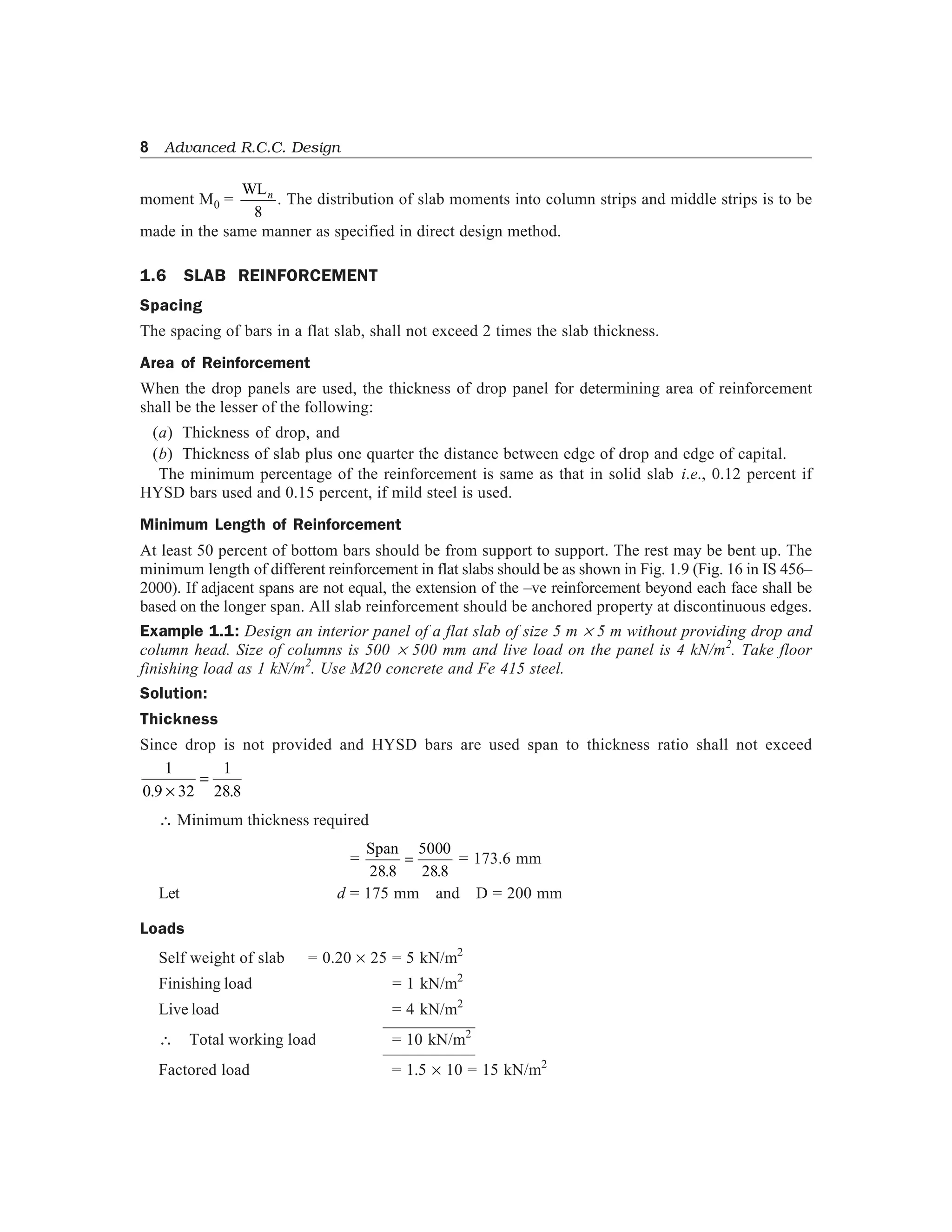
Shear Force
The critical section for shear shall be at a distance
d
2
from the periphery of the column/capital drop
panel. Hence if drops are provided there are two critical sections near columns. These critical sections
are shown in Figs. 1.1 to 1.4. The shape of the critical section in plan is similar to the support
immediately below the slab as shown in Fig. 1.6.
d/2
d/2
Critical
section
Support section
column / column head
( )a
d/2
Support
section
Critical
section ( )b
Fig. 1.6
For columns sections with re-entrant angles, the critical section shall be taken as indicated in Fig. 1.7.
Critical
section
Support
section
d/2
d/2
( )a
d/2
d/2
d/2
Critical
section
Support
section
( )b
Fig. 1.7
In case of columns near the free edge of a slab, the critical section shall be taken as shown in Fig. 1.8.
d/2
d/2
Critical
section
Free
edge
( )a
Critical
section
Free
corner
Corner
column
( )b
Fig. 1.8
7. Flat Slabs 7
The nominal shear stress may be calculated as
tv =
V
b d0
where V – is shear force due to design
b0 – is the periphery of the critical section
d – is the effective depth
The permissible shear stress in concrete may be calculated as ks tc, where ks = 0.5 + bc but not
greater than 1, where bc is the ratio of short side to long side of the column/capital; and
tc = 0 25. fck
If shear stress tv < tc – no shear reinforcement are required. If tc < tv < 1.5 tc, shear reinforcement
shall be provided. If shear stress exceeds 1.5 tc flat slab shall be redesigned.
1.5 EQUIVALENT FRAME METHOD
IS 456–2000 recommends the analysis of flat slab and column structure as a rigid frame to get design
moment and shear forces with the following assumptions:
(a) Beam portion of frame is taken as equivalent to the moment of inertia of flat slab bounded
laterally by centre line of the panel on each side of the centre line of the column. In frames
adjacent and parallel to an edge beam portion shall be equal to flat slab bounded by the edge and
the centre line of the adjacent panel.
(b) Moment of inertia of the members of the frame may be taken as that of the gross section of the
concrete alone.
(c) Variation of moment of inertia along the axis of the slab on account of provision of drops shall
be taken into account. In the case of recessed or coffered slab which is made solid in the region
of the columns, the stiffening effect may be ignored provided the solid part of the slab does not
extend more than 0.15 lef into the span measured from the centre line of the columns. The
stiffening effect of flared columns heads may be ignored.
(d) Analysis of frame may be carried out with substitute frame method or any other accepted
method like moment distribution or matrix method.
Loading Pattern
When the live load does not exceed ¾th of dead load, the maximum moments may be assumed to
occur at all sections when full design live load is on the entire slab.
If live load exceeds ¾th dead load analysis is to be carried out for the following pattern of loading also:
(i) To get maximum moment near mid span
– ¾th of live load on the panel and full live load on alternate panel
(ii) To get maximum moment in the slab near the support
– ¾th of live load is on the adjacent panel only
It is to be carefully noted that in no case design moment shall be taken to be less than those
occurring with full design live load on all panels.
The moments determined in the beam of frame (flat slab) may be reduced in such proportion that
the numerical sum of positive and average negative moments is not less than the value of total design
8. 8 Advanced R.C.C. Design
moment M0 =
WLn
8
. The distribution of slab moments into column strips and middle strips is to be
made in the same manner as specified in direct design method.
1.6 SLAB REINFORCEMENT
Spacing
The spacing of bars in a flat slab, shall not exceed 2 times the slab thickness.
Area of Reinforcement
When the drop panels are used, the thickness of drop panel for determining area of reinforcement
shall be the lesser of the following:
(a) Thickness of drop, and
(b) Thickness of slab plus one quarter the distance between edge of drop and edge of capital.
The minimum percentage of the reinforcement is same as that in solid slab i.e., 0.12 percent if
HYSD bars used and 0.15 percent, if mild steel is used.
Minimum Length of Reinforcement
At least 50 percent of bottom bars should be from support to support. The rest may be bent up. The
minimum length of different reinforcement in flat slabs should be as shown in Fig. 1.9 (Fig. 16 in IS 456–
2000). If adjacent spans are not equal, the extension of the –ve reinforcement beyond each face shall be
based on the longer span. All slab reinforcement should be anchored property at discontinuous edges.
Example 1.1: Design an interior panel of a flat slab of size 5 m ´ 5 m without providing drop and
column head. Size of columns is 500 ´ 500 mm and live load on the panel is 4 kN/m2
. Take floor
finishing load as 1 kN/m2
. Use M20 concrete and Fe 415 steel.
Solution:
Thickness
Since drop is not provided and HYSD bars are used span to thickness ratio shall not exceed
1
0 9 32
1
28 8. .×
=
Minimum thickness required
=
Span
28 8
5000
28 8. .
= = 173.6 mm
Let d = 175 mm and D = 200 mm
Loads
Self weight of slab = 0.20 ´ 25 = 5 kN/m2
Finishing load = 1 kN/m2
Live load = 4 kN/m2
Total working load = 10 kN/m2
Factored load = 1.5 ´ 10 = 15 kN/m2
9. Flat Slabs 9
Minimum
percentage
of steel
at section
50
Remainder
WITHOUT DROP PANEL WITH DROP PANEL
d
b
75 mm max
150 mm
d
b
c
24 BAR DIA OR
ed
b b
e
b
150 mm min.
DROPbd
b e
150 mmg
e
b
300 mm min.
g
EDGE OF
DROP
75 mm max.
150 mm
75 mm max.
150 mm150 mm
(ALL BARS) (ALL BARS)
150 mm
75 mm max.75 mm max.
150 mm
c
c
c
c a
a cc
ff
D
C
D D
C C
Clear span - ln
Face of support
interior support
Exterior
support
MiddleStripColumnstripStrip
Type
ofbars
StraightbarsBentbars*StraightbarsBentbars*
50
Remainder
50
Remainder
50
Remainder
100
50
Remainder
50
Remainder
50
Remainder
Clear span - ln
Face of support
interior support
C
0.15 maxl
o.15 maxl
0.125lmax
300 mm min. ALL BARS
EDGE OF
24BAR DIA OR
[NO SLAB CONTINUITY] [CONTINUITY PROVED] [NO SLAB CONTINUITY]
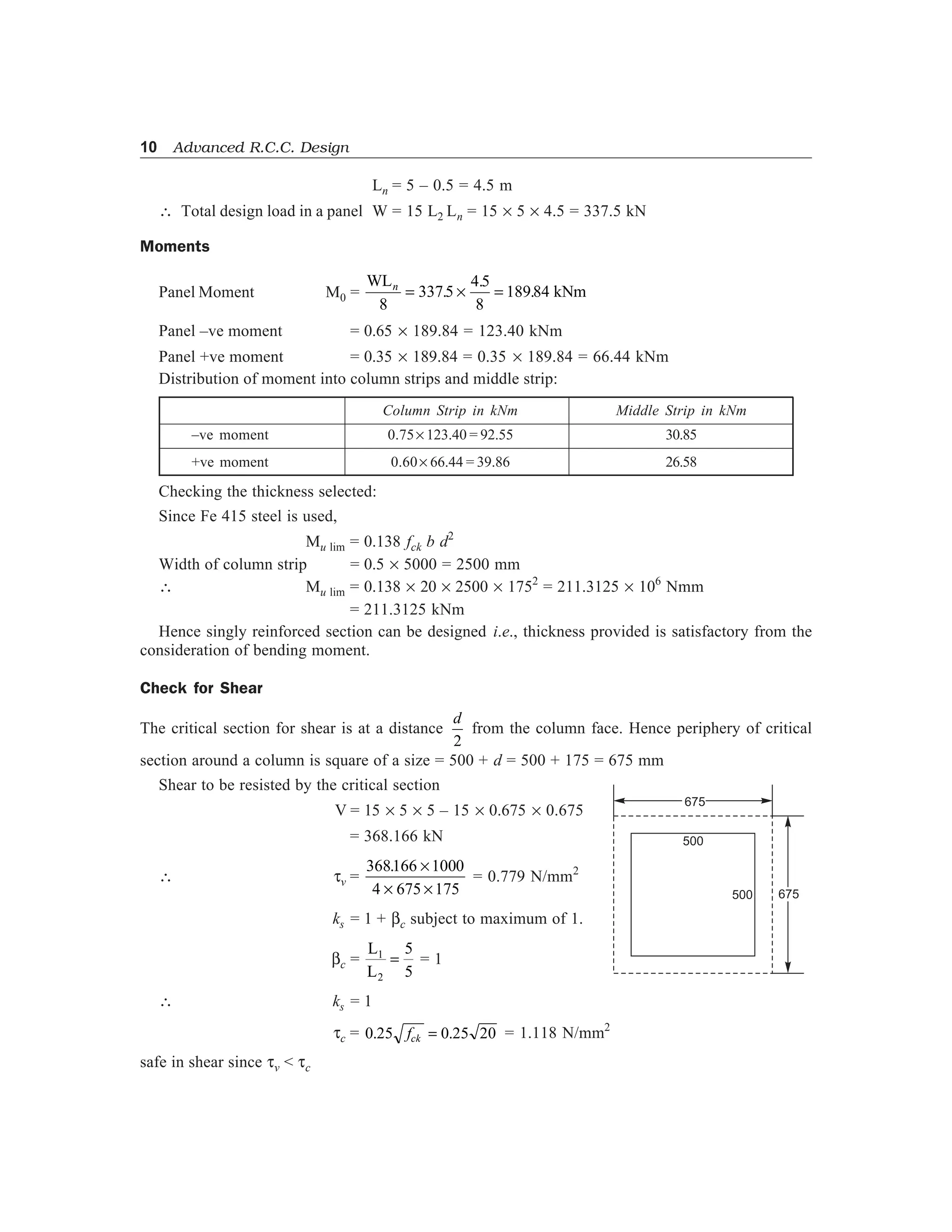
Bar Length From Face of Support
Minimum Length Maximum Length
Mark a b c d e f g
Length 0.14 ln 0.20 ln 0.22 ln 0.30 ln 0.33 ln 0.20 ln 0.24 ln
* Bent bars at exterior supports may be used if a general analysis is made.
Note. D is the diameter of the column and the dimension of the rectangular column in the direction under consideration.
Fig. 1.9 Minimum bend joint locations and extensions for reinforcement in flat slabs
10. 10 Advanced R.C.C. Design
Ln = 5 – 0.5 = 4.5 m
Total design load in a panel W = 15 L2 Ln = 15 ´ 5 ´ 4.5 = 337.5 kN
Moments
Panel Moment M0 =
WL
kNmn
8
3375
4 5
8
18984= ´ =.
.
.
Panel –ve moment = 0.65 ´ 189.84 = 123.40 kNm
Panel +ve moment = 0.35 ´ 189.84 = 0.35 ´ 189.84 = 66.44 kNm
Distribution of moment into column strips and middle strip:
Column Strip in kNm Middle Strip in kNm
–ve moment 0.75´ 123.40 = 92.55 30.85
+ve moment 0.60´ 66.44 = 39.86 26.58
Checking the thickness selected:
Since Fe 415 steel is used,
Mu lim = 0.138 fck b d2
Width of column strip = 0.5 ´ 5000 = 2500 mm
Mu lim = 0.138 ´ 20 ´ 2500 ´ 1752
= 211.3125 ´ 106
Nmm
= 211.3125 kNm
Hence singly reinforced section can be designed i.e., thickness provided is satisfactory from the
consideration of bending moment.
Check for Shear
The critical section for shear is at a distance
d
2
from the column face. Hence periphery of critical
section around a column is square of a size = 500 + d = 500 + 175 = 675 mm
Shear to be resisted by the critical section
V = 15 ´ 5 ´ 5 – 15 ´ 0.675 ´ 0.675
= 368.166 kN
tv =
368166 1000
4 675 175
. ×
× ×
= 0.779 N/mm2
ks = 1 + bc subject to maximum of 1.
bc =
L
L
1
2
5
5
= = 1
ks = 1
tc = 0 25 0 25 20. .fck = = 1.118 N/mm2
safe in shear since tv < tc
675
675500
500
11. Flat Slabs 11
Reinforcement
For –ve moment in column strip:
Mu = 92.55 kNm
92.55 ´ 106
= 0 87 1. f d
bd
f
f
y st
st y
ck
A
A
−
L
NM O
QP
= 0.87 ´ 415 ´ Ast ´ 175 1
2500 175
415
20
−
×
×
L
NM O
QPAst
i.e., 1464.78 = Ast 1
21084 3
−
L
NM O
QP
Ast
.
i.e., Ast
2
– 21084.3Ast + 1464.78 ´ 21084.3 = 0
Ast = 1583.74 mm2
This is to be provided in a column strip of width 2500 mm. Hence using 12 mm bars, spacing
required is given by
s =
p 4 12
1583 74
2500
2
´
´
.
= 178 mm
Provide 12 mm bars at 175 mm c/c.
For +ve moment in column strip:
Mu = 39.86 kNm
39.86 ´ 106
= 0.87 ´ 415 ´ Ast ´ 175 1
2500 175
415
20
−
×
×
L
NM O
QPAst
630.86 = Ast 1
21084 3
−
L
NM O
QP
Ast
.
or Ast
2
– 21084.3 Ast + 630.86 ´ 21084.3 = 0
Ast = 651 mm2
Using 10 mm bars, spacing required is
s =
p 4 10
651
2500
2
´
´ = 301.6 mm < 2 ´ thickness of slab
Hence provide 10 mm bars at 300 mm c/c.
Provide 10 mm diameter bars at 300 mm c/c in the middle strip to take up –ve and +ve moments.
Since span is same in both directions, provide similar reinforcement in other direction also.
12. 12 Advanced R.C.C. Design
Reinforcement Details
It is as shown in Fig. 1.10
50005000 5000
5000
5000
5000
Column Strip Middle Strip Column strip
ColumnStripMiddleStripColumnstrip
10-300 c/c
10-300 c/c
500
10 - 300 cc
200
500
Cover -25
12-175 c/c
Section through column strip
500 500
30003000 10 - 300 c/c
section through middle strip
Top reinforcement
Sign convention
Bottom reinforcement
12-175 c/c
12-175 c/c
Fig. 1.10 Reinforcement details [all dimension in mm units]
Example 1.2: Design an interior panel of a flat slab with panel size 6 ´ 6 m supported by columns of
size 500 ´ 500 mm. Provide suitable drop. Take live load as 4 kN/m2
. Use M20 concrete and Fe 415
steel.
Solution :
Thickness : Since Fe 415 steel is used and drop is provided, maximum span to thickness ratio
permitted is 32
Thickness of flat slab =
6000
32
= 187.5 mm
Provide 190 mm thickness. Let the cover be 30 mm
Overall thickness D = 220 mm
Let the drop be 50 mm. Hence at column head, d = 240 mm and D = 270 mm
13. Flat Slabs 13
Size of Drop
It should not be less than
1
3
6´ m = 2 m
Let us provide 3 m ´ 3 m drop so that the width of drop is equal to that of column head.
Width of column strip = width of middle strip = 3000 mm.
Loads
For the purpose of design let us take self-weight as that due to thickness at column strip
Self-weight = 0.27 ´ 1 ´ 1 ´ 25 = 6.75 kN/m2
Finishing load = 1.00 kN/m2
Live load = 4.00 kN/m2
Total load = 11.75 kN/m2
Design (factored) load = 1.5 ´ 11.75 = 17.625 kN/m2
Clear span Ln = 6 – 0.5 = 5.5 m
Design load W0 = Wu ´ L2 ´ Ln
= 17.625 ´ 6 ´ 5.5
= 581.625 kN
Design Total Moment
Total moment
M0 =
W L0
8
581625 55
8
n
=
´. .
= 400 kNm
Total negative moment = 0.65 ´ 400 = 260 kNm
Total positive moment = 0.35 ´ 400 = 140 kNm
The above moments are to be distributed into column strip and middle strip
Column Strip Middle Strip
–ve moment 0.75´ 260 = 195 kNm 0.25´ 260 = 65 kNm
+ve moment 0.6´ 140 = 84 kNm 0.4´ 140 = 56 kNm
Width of column strip = width of middle strip = 3000 mm
Mu lim = 0.138 fck b d2
= 0.138 ´ 20 ´ 3000 ´ 2402
= 476.928 ´ 106
Nmm
= 476.928 kNm
Thus Mu lim > Mu. Hence thickness selected is sufficient.
Check for Shear
The critical section is at a distance
14. 14 Advanced R.C.C. Design
d
2
=
240
2
= 120 mm from the face of column
It is a square of size = 500 + 240 = 740 mm
V = Total load – load on 0.740 ´ 0.740 area
= 17.625 ´ 6 ´ 6 – 17.625 ´ 0.740 ´ 0.740
= 624.849 kN
Nominal shear = tv =
624 489 1000
4 740 240
. ×
× ×
= 0.880 N/mm2
Shear strength = ks tc
where ks = 1 + bc subject to maximum of 1
where bc =
L
L
1
2
= 1
ks = 1
tc = 0 25 20. = 1.118 N/mm2
Design shear stress permitted
= 1.118 N/mm2
> tv
Hence the slab is safe in shear without shear reinforcement also.
Shear strength may be checked at distance
d
2
from drop. It is quite safe since drop size is large.
Reinforcement
(a) For –ve moment in column strip
Mu = 195 kNm
Thickness d = 240 mm
Mu = 0.87 fy Ast d 1 −
×
×
L
NM O
QPAst y
ckb d
f
f
195 ´ 106
= 0.87 ´ 415 ´ Ast ´ 240 1
3000 240
415
20
−
×
×
L
NM O
QPAst
2250.38 = Ast 1
34698 8
−
L
NM O
QP
Ast
.
Ast
2
– 34698.8 Ast + 2250.38 ´ 34698.8 = 0
Ast = 2419 mm2
in 3000 mm width
500
500
500 740
740
120 120
15. Flat Slabs 15
Using 12 mm bars, spacing required is
s =
p 4 12
2419
3000
2
´
´ = 140.26 mm
Provide 12 mm bars at 140 mm c/c
(b) For +ve moment in column strip
Mu = 84 kNm = 84 ´ 106
Nmm. Thickness d = 190 mm
84 ´ 106
= 0.87 ´ 415 ´ Ast ´ 190 1
3000 240
415
20
−
×
×
L
NM O
QPAst
1224.5 = Ast 1
27469 9
−
L
NM O
QP
Ast
.
Ast = 1285 mm2
Using 10 mm bars
s =
p 4 10
1285
3000
2
´
´ = 183 mm
Provide 10 mm bars at 180 mm c/c
(c) For –ve moment in middle strip:
Mu = 65 kNm; Thickness = 190 mm
65 ´ 106
= 0.87 ´ 415 ´ Ast ´ 190 1
3000 190
415
20
−
×
×
L
NM O
QPAst
947.5 = Ast 1
27469 9
−
L
NM O
QP
Ast
.
Ast
2
– 27469.9 Ast + 947.5 ´ 27469.9 = 0
Ast = 983 mm2
in 3000 mm width
Using 10 mm bars
s =
p 4 10
983
3000
2
´
´ = 239.7 mm
Provide 10 mm bars at 230 mm c/c
(d) For +ve moment in middle strip
Mu = 56 kNm; Thickness = 190 mm
Provide 10 mm bars at 230 mm c/c in this portion also.
Since span is same in both direction, provide similar reinforcement in both directions. The details
of reinforcement are shown in Fig. 1.11.
16. 16 Advanced R.C.C. Design
6000
Column strip
Middle strip
Column strip
Columnstrip
Middlestrip
Columnstrip
6000 6000
6000
6000
6000
=Do p widthr=Do p widthr
=Dorpwidth=Dorpwidth
12 140 c/c–
10 230 c/c–
500 500
240
10 230@
12 @ 140 10 180 c/c@
190
Cover - 30
Section through column strip
10 230 c/c@
240
190
500 500
10 180c/c–
12 230c/c–
10–180c/c
Fig. 1.11 Reinforcement details
Example 1.3: Design the interior panel of the flat slab in example 1.2, providing a suitable column
head, if columns are of 500 mm diameter.
Solution: Let the diameter of column head be
= 0.25L = 0.25 ´ 6 = 1.5 m
It’s equivalent square has side ‘a’ where
π
4
152
× . = a2
a = 1.33 m
Ln = 6 – 1.33 = 4.67 m
W0 = 17.625 ´ 6 ´ 4.67 = 493.85 kN
M0 =
W Lo n
8
49385 4 67
8
=
×. .
= 288.3 kNm
17. Flat Slabs 17
Total –ve moment = 0.65 ´ 288.3 = 187.4 kNm
Total +ve moment = 0.35 ´ 288.3 = 100.9 kNm
The distribution of above moment into column strip and middle strips are as given below:
Column Strip Middle Strip
–ve moment 0.75´ 187.4 = 140.55 kNm 0.25´ 187.4 = 46.85kNm
+ve moment 0.60´ 100.9 = 60.54kNm 0.4´ 100.9 = 40.36kNm
Width of column strip = width of middle strip = 3000 mm
Mu lim = 0.138 fck bd2
= 0.138 ´ 20 ´ 3000 ´ 2402
= 476.928 ´ 106
Nmm > Mu
Hence thickness selected is sufficient.
Check for Shear
The critical section is at a distance
d
2
=
240
2
= 120 mm from the face of column head
Diameter of critical section = 1500 + 240 =1740 mm
= 1.740 m
Perimeter of critical section = p D
= 1.740 p
Shear on this section
V = 17 625 6 6
4
1742
. .´ - ´
L
NM O
QP
p
= 592.59 kN
tv =
592 59 1000
1740 240
. ×
× ×π
= 0.45 N/mm2
Maximum shear permitted = ks × 0 25 20.
= 1.118 N/mm2
Since ks works out to be 1
Since maximum shear permitted in concrete is more than nominal shear tv, there is no need to
provide shear reinforcement
Design of Reinforcement
(a) For –ve moment in column strip
Mu = 140.55 kNm; d = 240 mm
140.55 ´ 106
= 0.87 ´ 415 ´ Ast ´ 240 1
3000 240
415
20
−
×
×
L
NM O
QPAst
1622 = Ast 1
34698 8
−
L
NM O
QP
Ast
.
1500 120
18. 18 Advanced R.C.C. Design
Ast
2
– 34698.8 Ast + 1622 ´ 34698.8 = 0
Ast = 1705 mm2
Using 12 mm bars,
s =
π 4 12
1705
3000
2
×
× = 199 mm
Provide 12 mm bars at 190 mm c/c.
(b) For the +ve moment in column strip
Mu = 60.54 kNm; d = 190 mm
60.54 ´ 106
= 0.87 ´ 415 ´ Ast ´ 190 1
3000 190
415
20
−
×
×
L
NM O
QPAst
882.51 = Ast 1
27469 9
−
L
NM O
QP
Ast
.
Ast
2
– 27469.9 Ast + 882.51 ´ 27469.9 = 0
Ast = 913 mm2
Using 10 mm bars
s =
π 4 10
913
3000
2
×
× = 258 mm
Provide 10 mm bars at 250 mm c/c.
(c) For –ve moment in middle strip:
Mu = 46.85 kNm; d = 190 mm
46.85 ´ 106
= 0.87 ´ 415 ´ Ast ´ 190 1
3000 190
415
20
−
×
×
L
NM O
QPAst
683 = Ast 1
27469 9
−
L
NM O
QP
Ast
.
Ast
2
– 27469.9Ast + 683 ´ 27469.9 = 0
Ast = 701 mm2
Using 10 mm bars,
s =
π 4 10
701
3000
2
×
× = 336 mm
Provide 10 mm bars at 300 mm c/c.
(d) Provide 10 mm bars at 300 mm c/c for +ve moment in middle strip also.
As span is same in both directions, provide similar reinforcement in both directions. Reinforcement
detail may be shown as was done in previous problem.
Example 1.4: A flat slab system consists of 5 m ´ 6 m panels and is without drop and column head.
It has to carry a live load of 4 kN/m2
and a finishing load of 1 kN/m2
. It is to be designed using M20
grade concrete and Fe 415 steel. The size of the columns supporting the system is 500 ´ 500 mm and
floor to floor height is 4.5 m. Calculate design moments in interior and exterior panels at column and
middle strips in both directions.
19. Flat Slabs 19
Solution:
Thickness: Since Fe 415 steel is used and no drops are provided, longer span to depth ratio is not
more than 32 ´ 0.9 = 28.8
d =
6000
28 8.
= 208
Let us select d = 210 mm and D = 240 mm
Loads
Self weight 0.24 ´ 1 ´ 1 ´ 25 = 6 kN/m2
Finishing weight = 1 kN/m2
Live load = 4 kN/m2
Total = 11 kN/m2
Wu = 1.5 ´ 11 = 16.5 kN/m2
Panel Dimensions
Along length
L1 = 6 m and L2 = 5 m
Width of column strip = 0.25 L1 or L2 whichever is less.
= 0.25 ´ 5 = 1.25 m on either side of column centre line
Total width of column strip = 1.25 ´ 2 = 2.5 m
Width of middle strip = 5 – 2.5 = 2.5 m
Along Width
L1 = 5 m L2 = 6 m
Width of column strip = 0.25 ´ 5 = 1.25 m on either side
Total width of column strip = 2.5 m
Hence, width of middle strip = 6 – 2.5 = 3.5 m
INTERIOR PANELS
Moments Along Longer Size
L1 = 6 m L2 = 5 m
Ln = 6 – 0.5 = 5.5 m subject to minimum of 0.65 ´ L1 = 3.9 m
Ln = 5.5 m
Load on panel W0 = 16.5 ´ L2Ln
= 16.5 ´ 5 ´ 5.5 = 453.75 kN
20. 20 Advanced R.C.C. Design
M0 =
W L0
8
45375 55
8
n
=
´. .
= 311.95 kNm
Appropriation of Moment
Total –ve moment = 0.65 ´ 311.95 = 202.77 kNm
Total +ve moment = 311.95 – 202.77 = 109.18 kNm
Hence moment in column strip and middle strip along longer direction in interior panels are as given
below:
Column Strip Middle Strip
–ve moment 0.75´ 202.75 = 152.06 kNm 202.75 – 152.06 = 50.69kNm
+ve moment 0.60´ 109.18 = 65.51kNm 109.18 – 65.51 = 43.67kNm
Along Width
L1 = 5 m L2 = 6 m and Ln = 5 – 0.5 = 4.5 m.
Panel load = W0 = 16.5 ´ 6 ´ 4.5 = 445.5 kN
Panel moment M0 = W
L
0
8
4455 45
8
n
=
´. .
= 250.59 kN-m
Appropriation of Moment:
Total –ve moment = 0.65 ´ 250.59 = 162.88 kN-m
Total +ve moment = 250.59 – 162.88 = 87.71 kN-m
Moments in column strip and middle strip are as shown below:
Column Strip Middle Strip
–ve moment 0.75´ 162.88 = 122.16 kNm 0.25´ 162.88 = 40.72kNm
+ve moment 0.60´ 87.71 = 52.63kNm 0.40´ 87.71 = 35.08kNm
EXTERIOR PANELS
Length of column = 4.5 – 0.24 = 4.26 m
The building is not restrained from lateral sway. Hence as per Table 28 in IS 456-2000, effective
length of column
= 1.2 ´ length = 1.2 ´ 4.26 = 5.112 m
Size of column = 500 ´ 500 mm
Moment of inertia of column =
1
12
5004 4
× mm
21. Flat Slabs 21
kc =
I
L
1
12
= ×
500
5112
4
= 101844 mm4
LONGER SPAN DIRECTION
Moment of inertia of beam
Is = Moment of inertia of slab
=
1
12
6000 2403
× ×
Its length = L2 = 5000 mm
kc =
I
5000
s
= ´
´1
12
6000 240
5000
3
= 1382400 mm4
Live load
Dead load
=
4
7
< 0.75
Relative stiffness ratio is
ac =
k k
k
c c
s
1 2 2 1018844
1382400
+
=
×
= 1.474
a = 1
1
1
1
1474
+ = +
ac .
= 1.678
Hence various moment coefficients are:
Interior –ve moment coefficient = 0.75 –
01.
α
= 0.690
Exterior –ve moment coefficient =
0.65
α
= 0.387
Positive moment coefficient = 0.63 –
0.28
α
= 0.463
Total moment M0 = 311.95 kNm
Appropriation of moments in kNm is as given below:
Total Column Strip Middle Strip
Interior –ve 0.69´ 311.95 = 215.25 0.75´ 215.25 = 161.43 215.25 – 161.43 = 53.82
Exterior –ve 0.387´ 311.95 = 120.72 1.00´ 120.72 = 120.72 120.72 – 120.72 = 0
+ Moment 0.463´ 31.95 = 144.43 0.60´ 144.43 = 86.66 144.43 – 86.66 = 57.77
Shorter Span Direction
ks =
1
12
5000 240
6000
3
×
×
= 96000
ac =
k k
k
c c
s
1 2 2 1018844
960000
+
=
×
= 2.123
22. 22 Advanced R.C.C. Design
a1 = 1
1
+
αc
= 1.471
Interior –ve moment coefficient = 0.75 –
0 1
0 75
0 1
1 471
.
.
.
.a
= - = 0.682
Exterior –ve moment coefficient =
0.65 0.65
α
=
1 471.
= 0.442
Positive moment coefficient = 0.63 –
0.28 0.28
α
= −0 63
1 471
.
.
= 0.440
Total moment M0 = 250.59 kNm
Appropriation of moments in shorter span exterior panel in kNm is as given below:
Total Column Strip Middle Strip
Interior –ve 0.682´ 250.59 = 170.90 0.75´ 170.76 = 128.18 170.90 – 128.18 = 42.72
Exterior -ve 0.442´ 250.59 = 110.76 1.00´ 110.76 = 110.76 110.76 – 110.76 = 0
+ Moment 0.44´ 250.59 = 110.25 0.60´ 110.25 = 66.16 110.25 – 66.16 = 44.09
In the exterior panel in each column strips half the above values will act. These moments are
shown in Fig. 1.12
Strip
Col Middle
Strip
2.5
1.25
Strip
Col Middle
Strip Strip
Col
2.5 2.5 2.5
–120.72
–122.16
–53.82
52.63
–161.43 –15.06
2
–122.16
–50.69
52.63
–152.06
–122.16
86.66
2
–40.72
57.77
35.08
–40.72
43.67
35.08
65.51
–40.72
–152.06
–122.16
2
–128.18
–50.69
66.16
2
–161.43 –152.06
2
–122.16
2–128.18
66.16
2
52.63
2
–53.82120.72
–122.16
2
–128.18
86.66
2
–42.72
57.77
44.09
–42.72
43.67
44.09
65.51
–42.72
–152.06
–110.76
66.16
–50.69
–161.43
–152.06
2
–110.76
66.16
2
–53.82120.72
–4
–110.76
2.5 m
2.5 m
3.5 m
3.5 m
1.25 m
86 66
2
65 51
2
. .
+
86 66
2
65 51
2
. .
+
52 63
2
.
Fig. 1.12
23. Flat Slabs 23
REVIEW QUESTIONS
1. Design the typical interior panel of a flat slab floor of size 5 m ´ 5 m with suitable drop to
support a live load of 4 kN/m2
. The floor is supported by columns of size 450 mm ´ 450 mm.
Use M20 concrete and Fe 415 steel. Sketch the reinforcement details by showing cross sec-
tions
(i) at column strip
(ii) at middle strip.
2. Design the exterior panel of a flat slab of size 6 m ´ 6 m with suitable drop to support a live load
of 5 kN/m2
. The floor system is supported by columns of size 500 mm ´ 500 mm. Floor to
floor distance is 3.6 m. Use M20 concrete and Fe 415 steel.
3. For the flat slab system of size 6 m ´ 6 m provide suitable drop and fix up overall dimensions.
The floor system is supported by columns of size 500 mm ´ 500 mm, the floor height being 3.6 m.
Calculate the design moments at various strips in the interior and exterior panels. Give the plan
of the floor system showing these design moments.