The document discusses automation and how to get started with automation. It can be divided into two main sections:
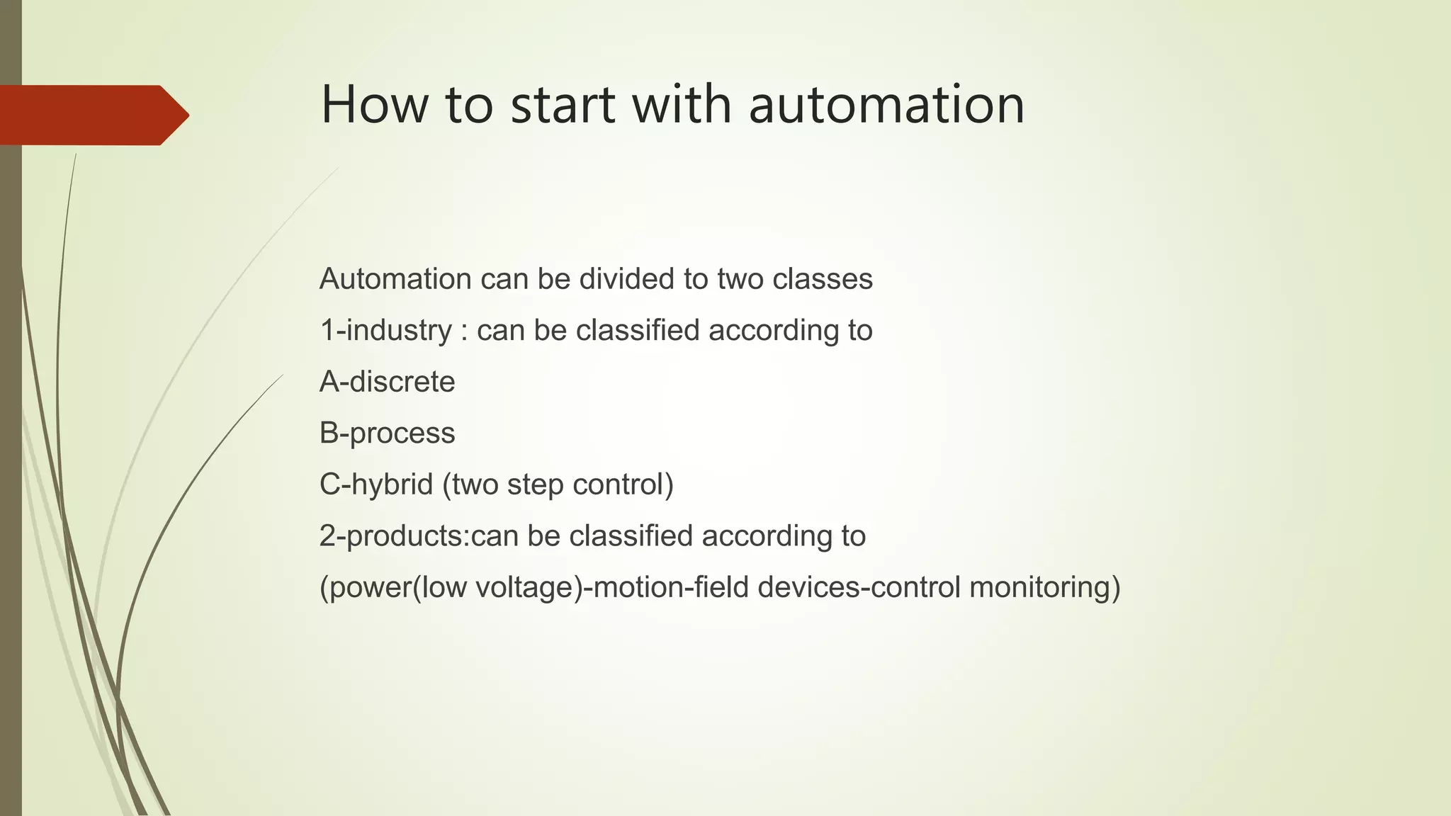
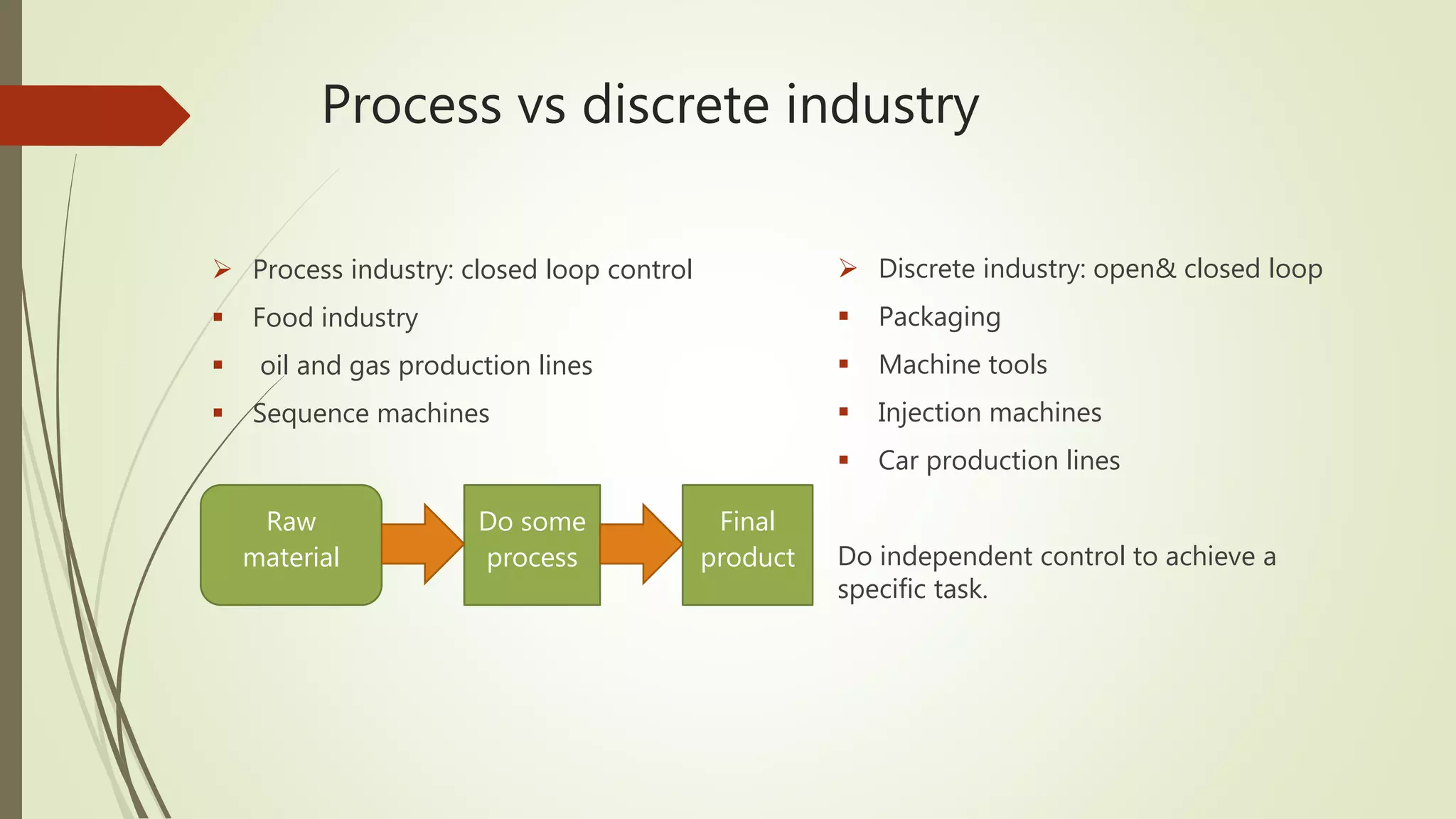
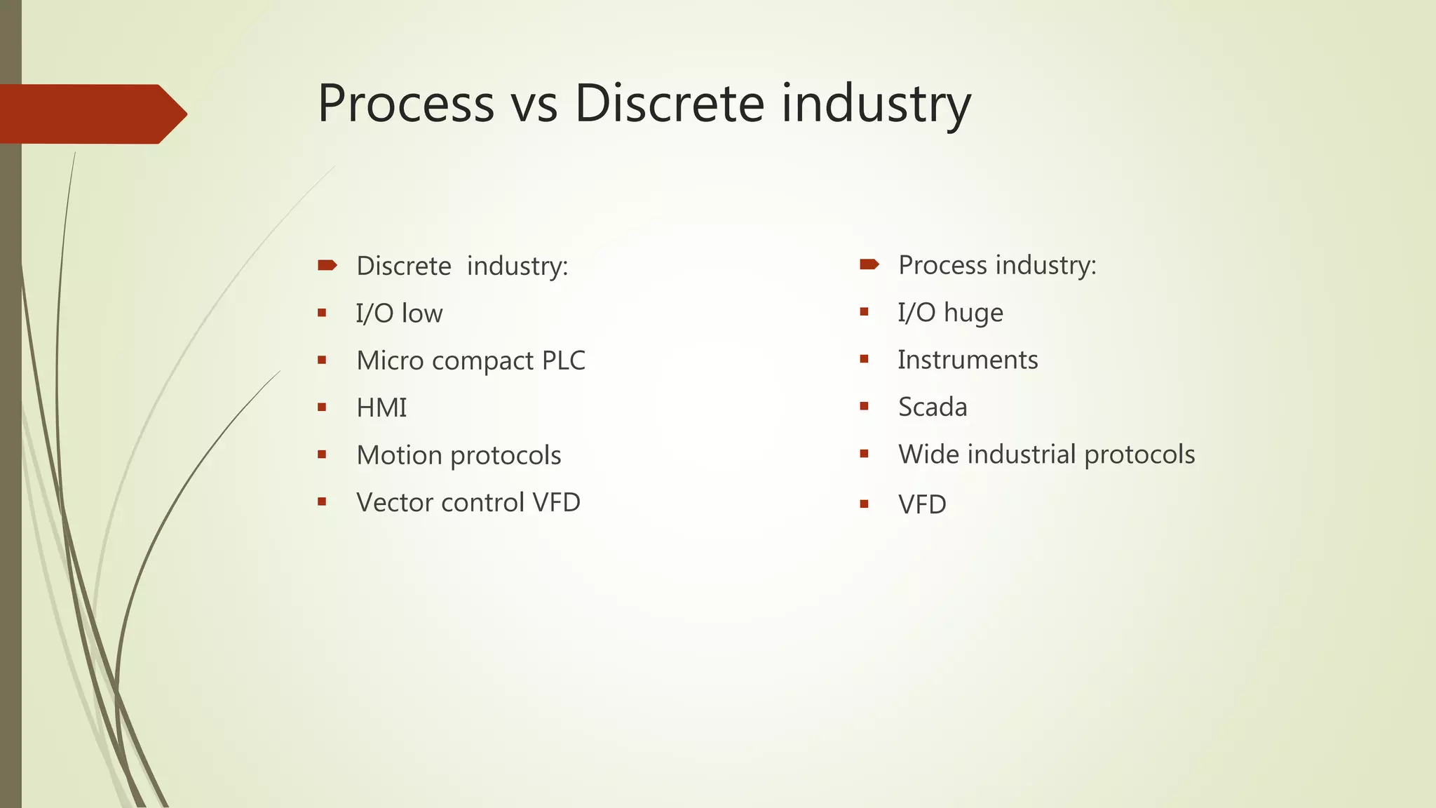
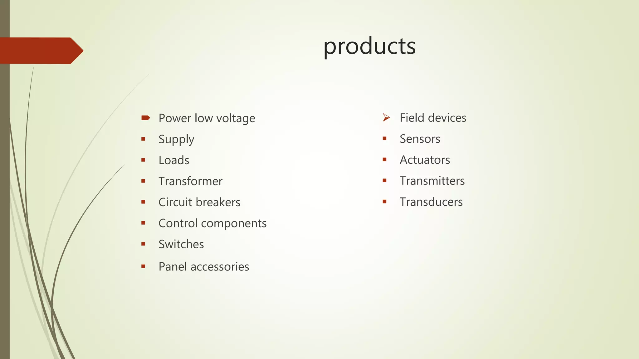
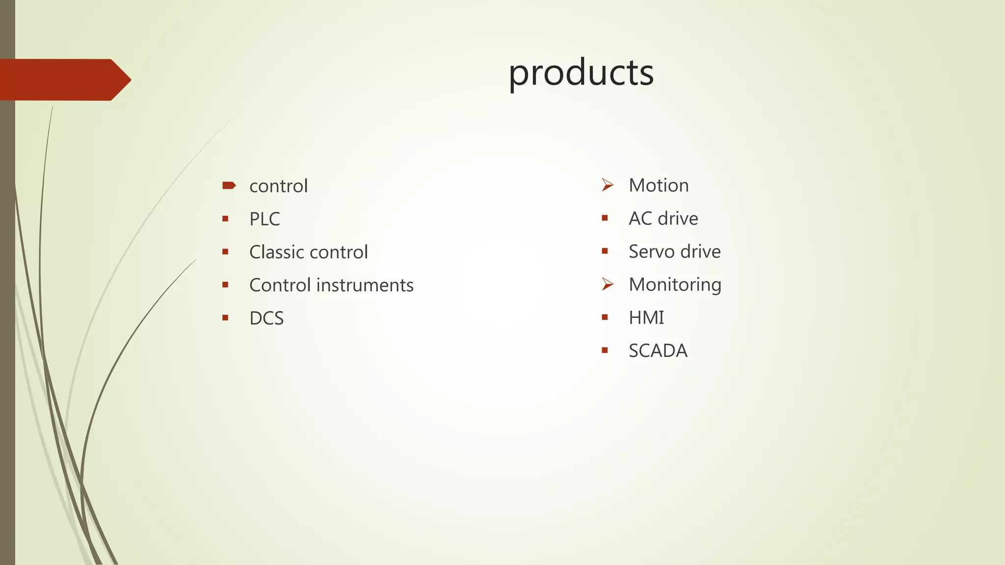
1) It classifies automation into industry automation (discrete, process, hybrid) and products (power, motion, field devices, control/monitoring). Discrete industry uses PLCs and closed/open loop control while process uses large I/O, instruments, and SCADA.
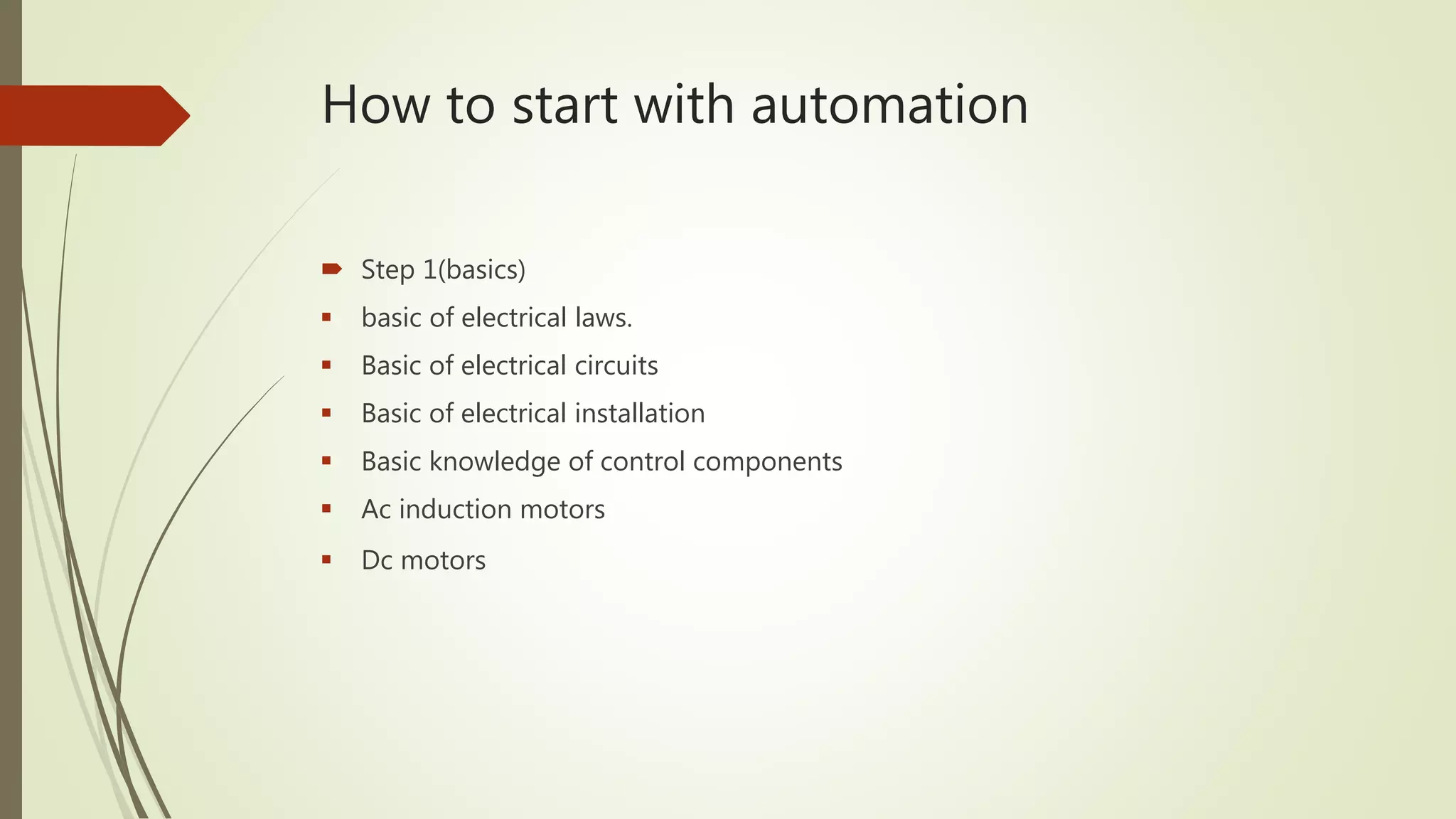
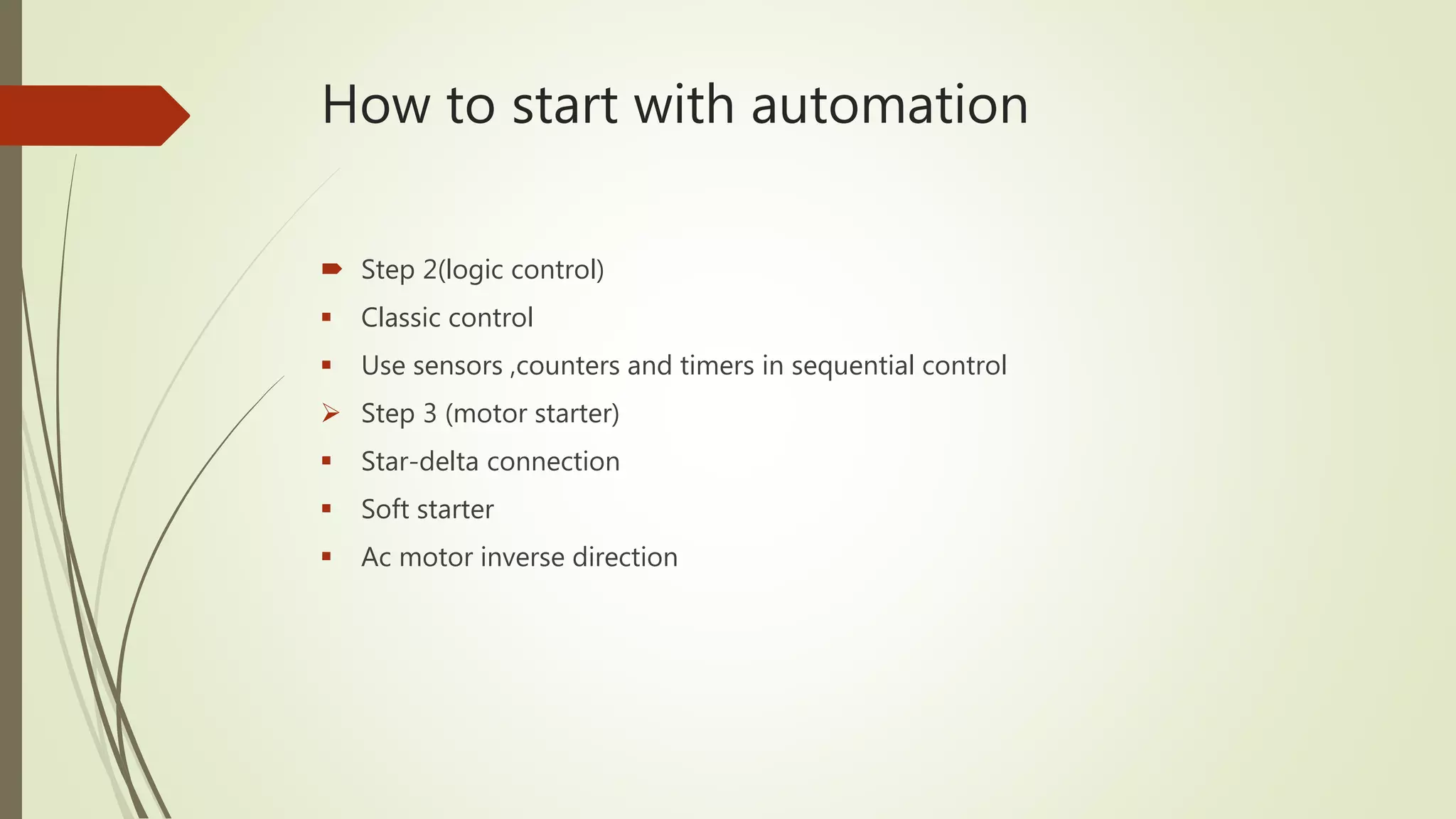
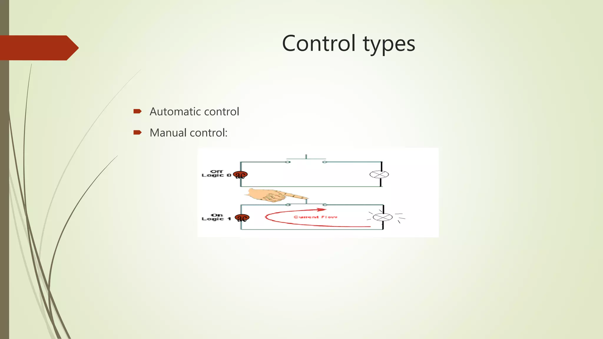
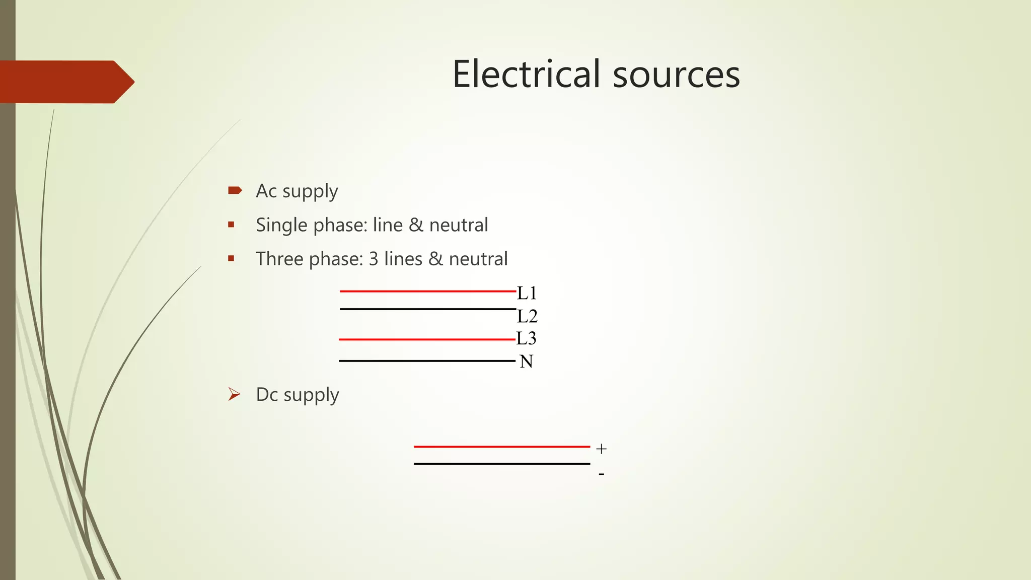
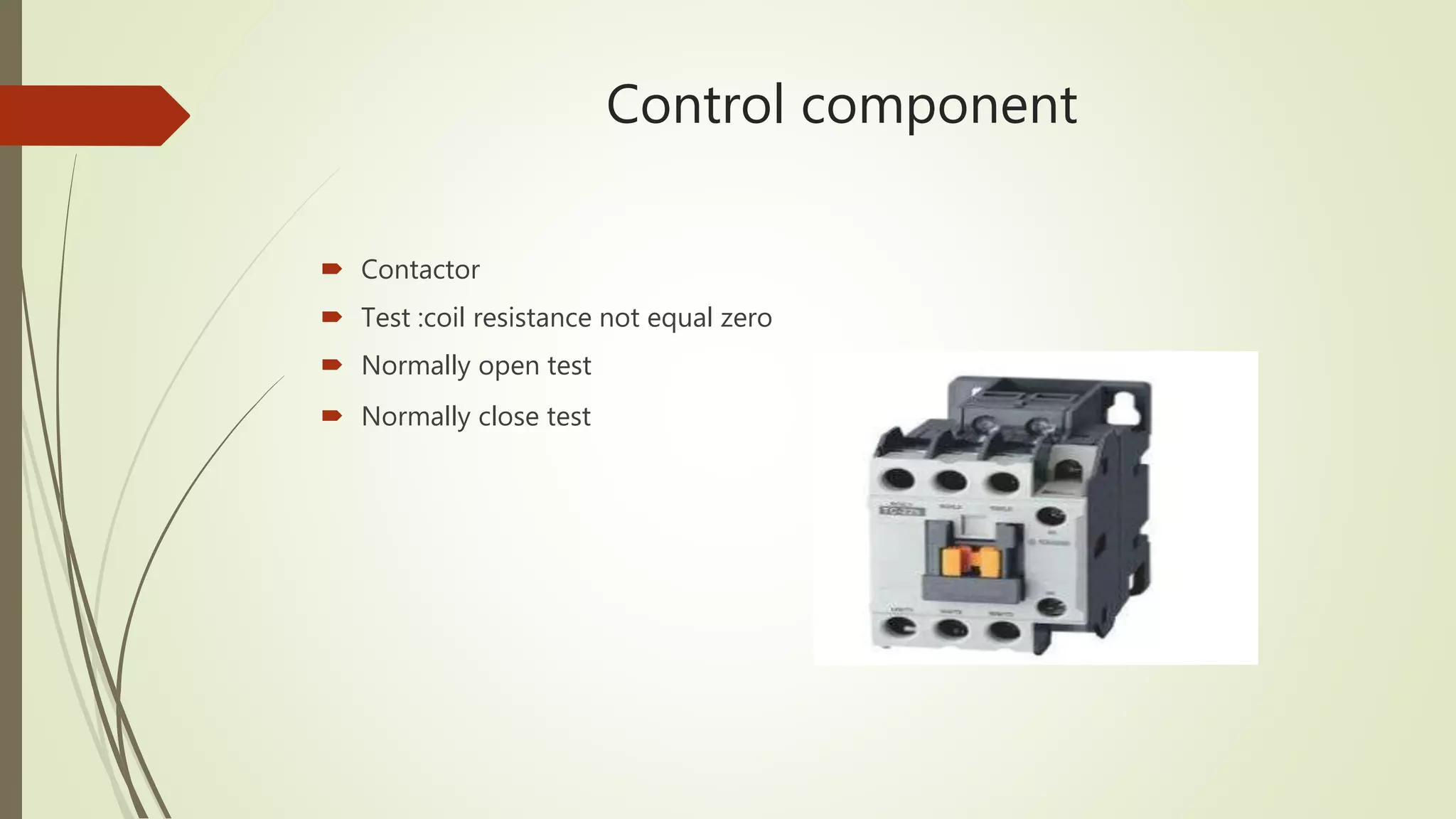
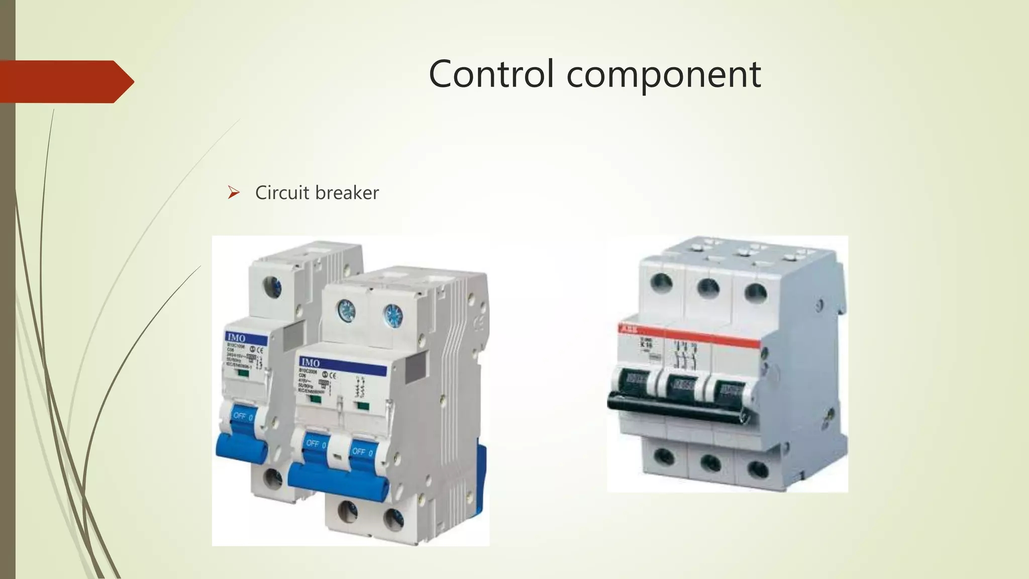
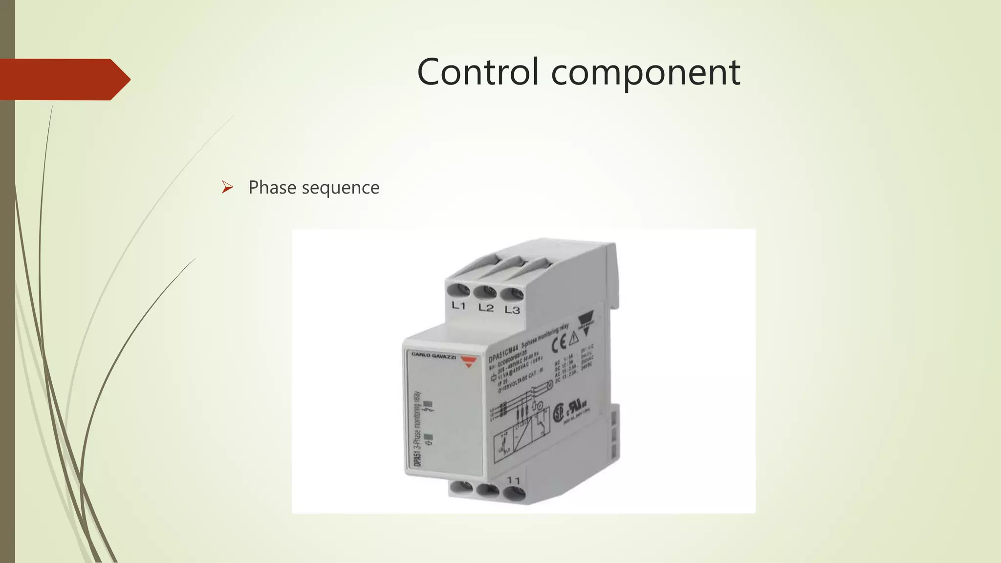
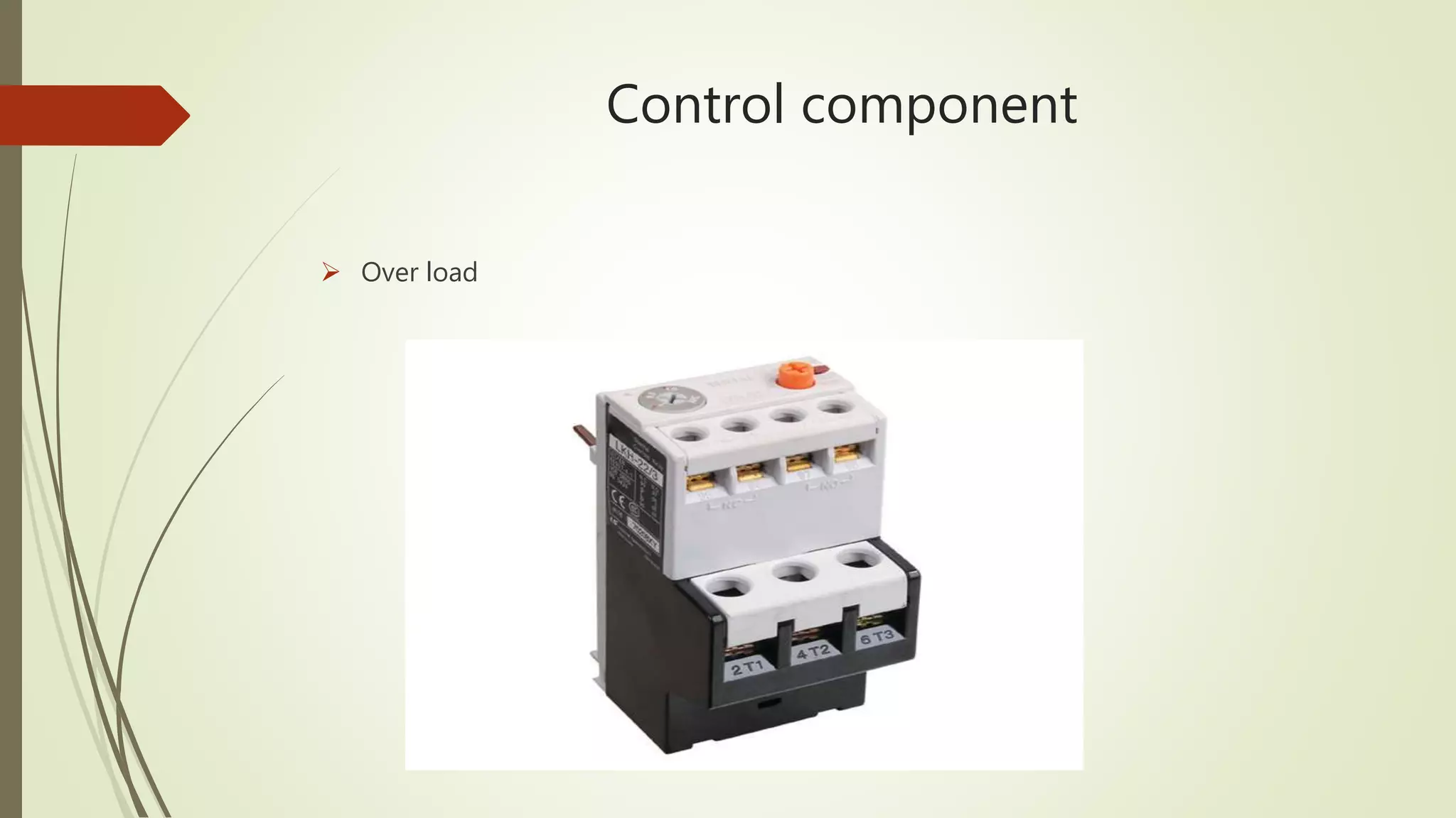
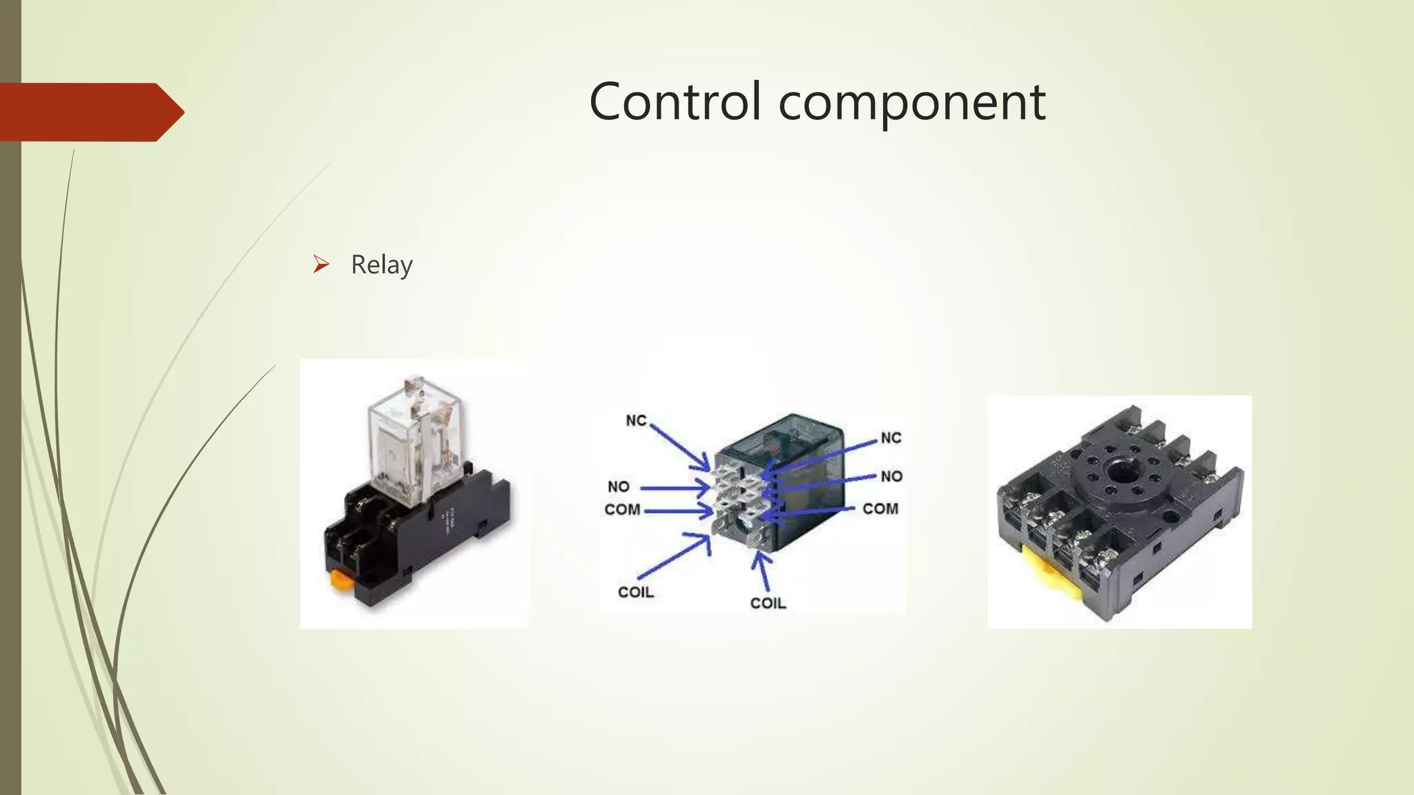
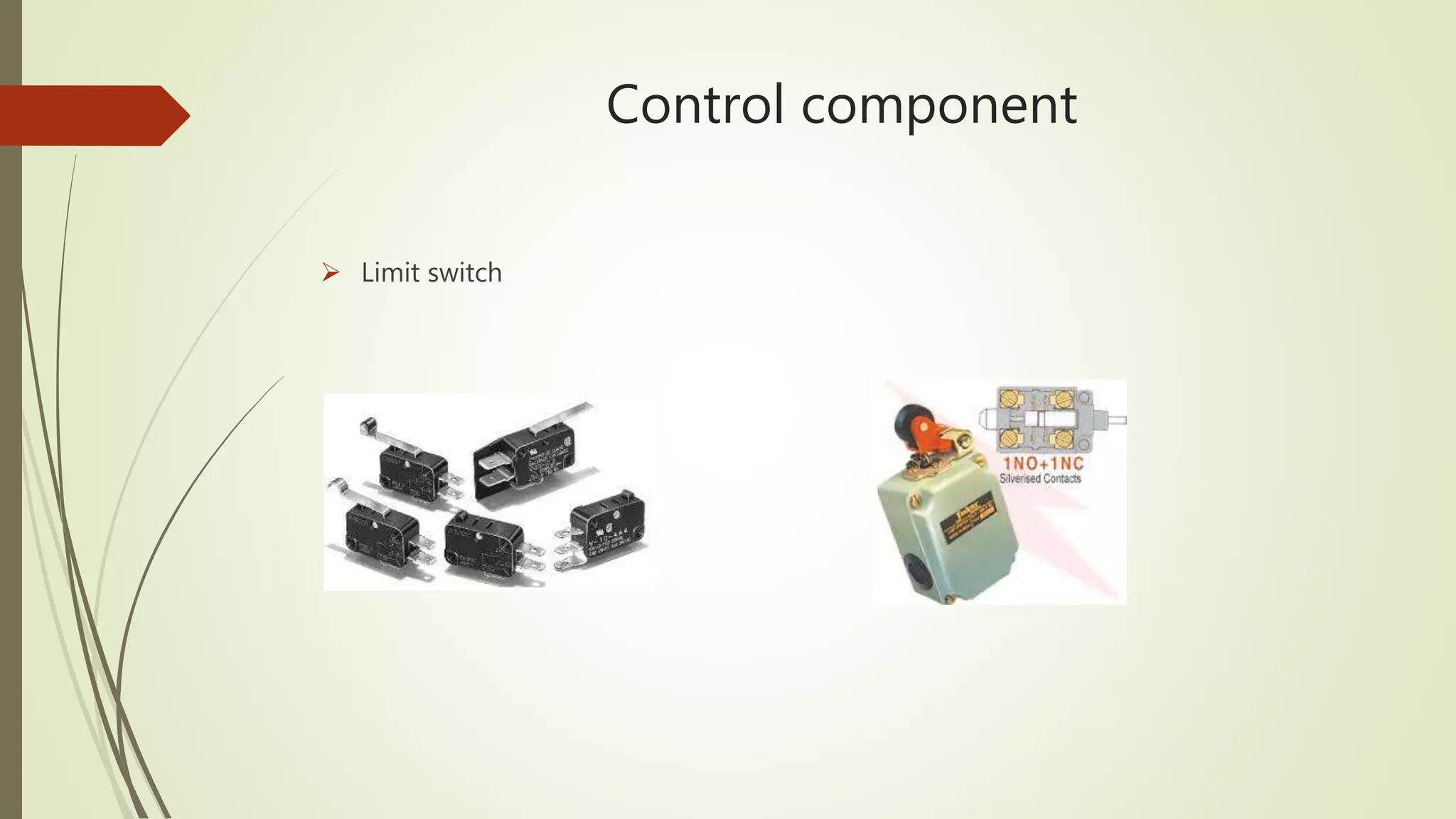
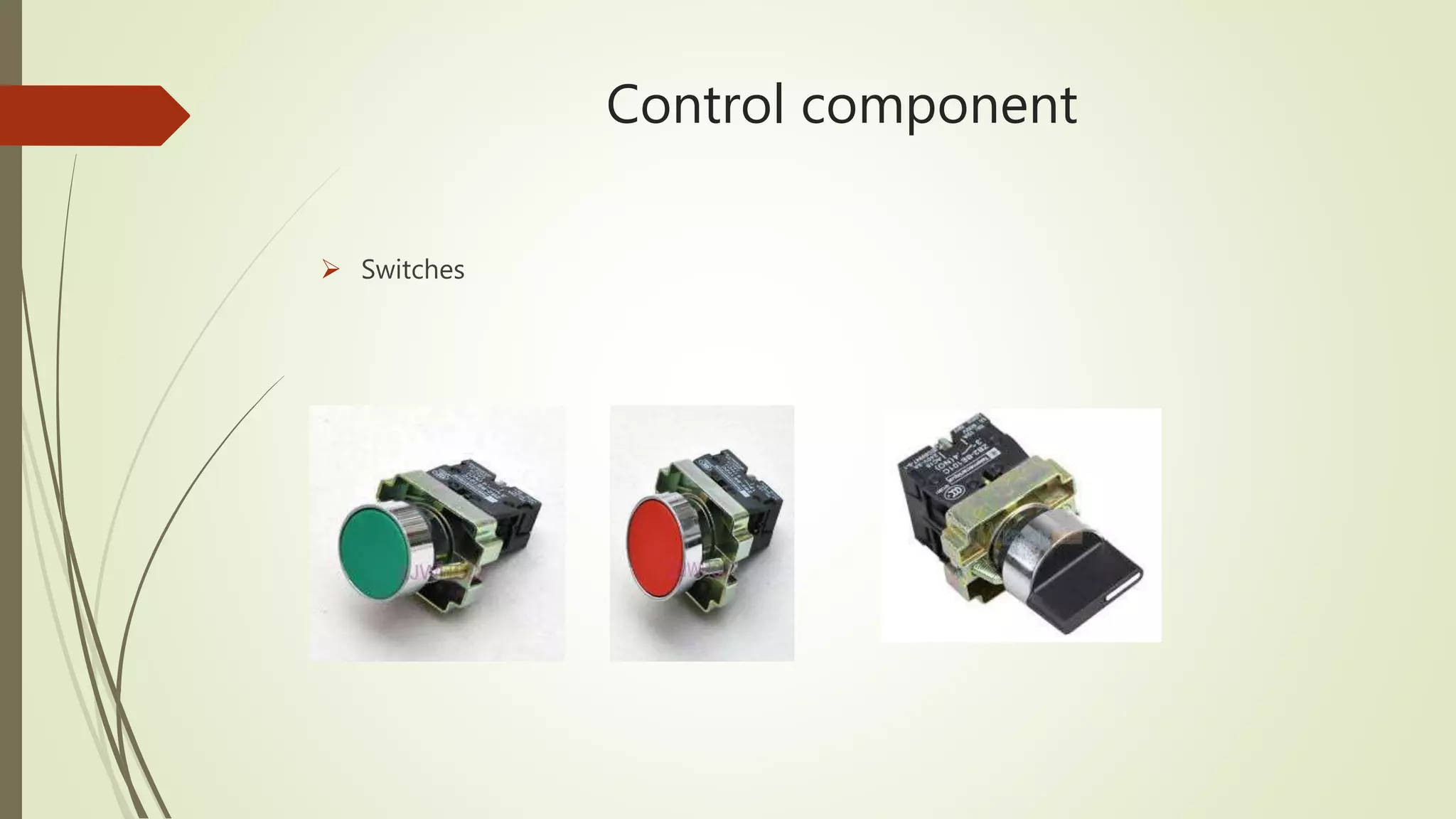
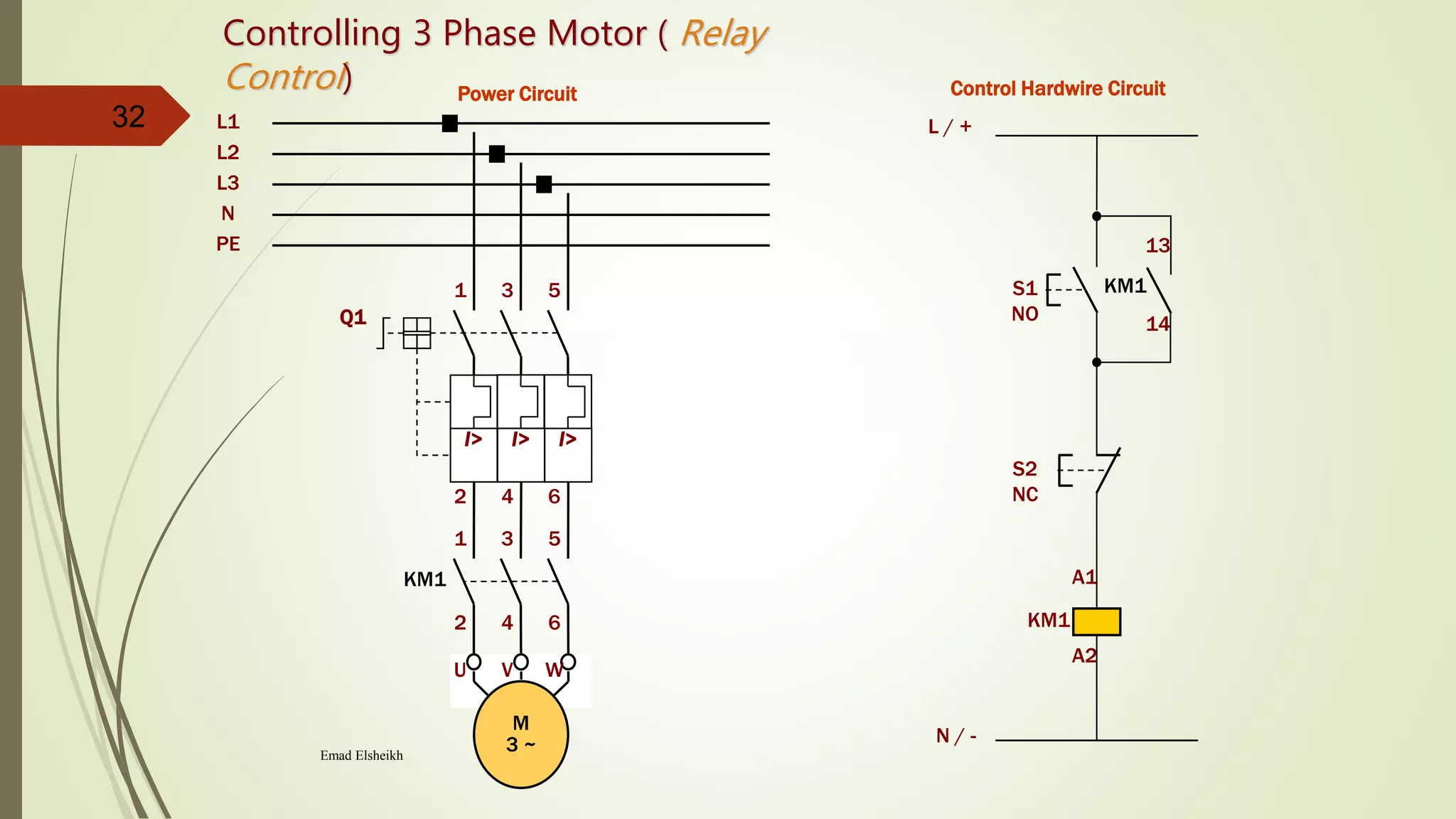
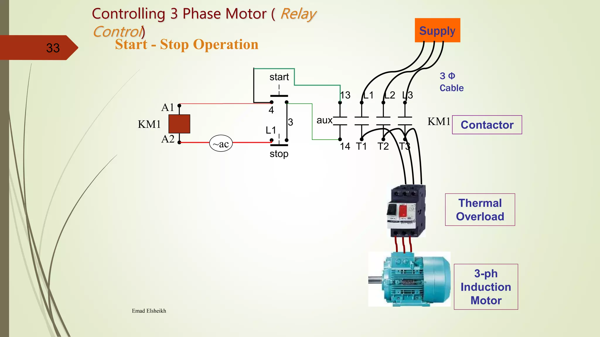
2) It provides steps to get started with automation from basics of electrical circuits to PLC programming to industrial communication. It covers electrical components, control circuits, motors, and programming basics. Automation combines electrical, mechanical, and software systems to control equipment and processes.