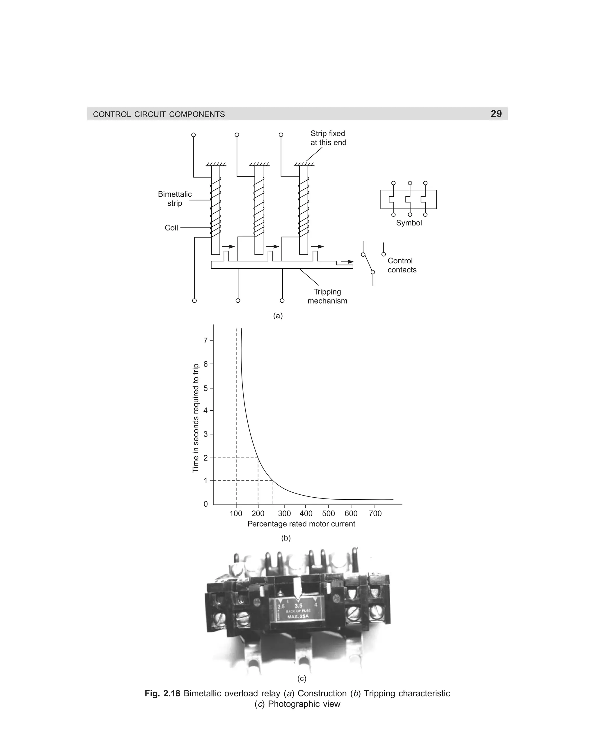
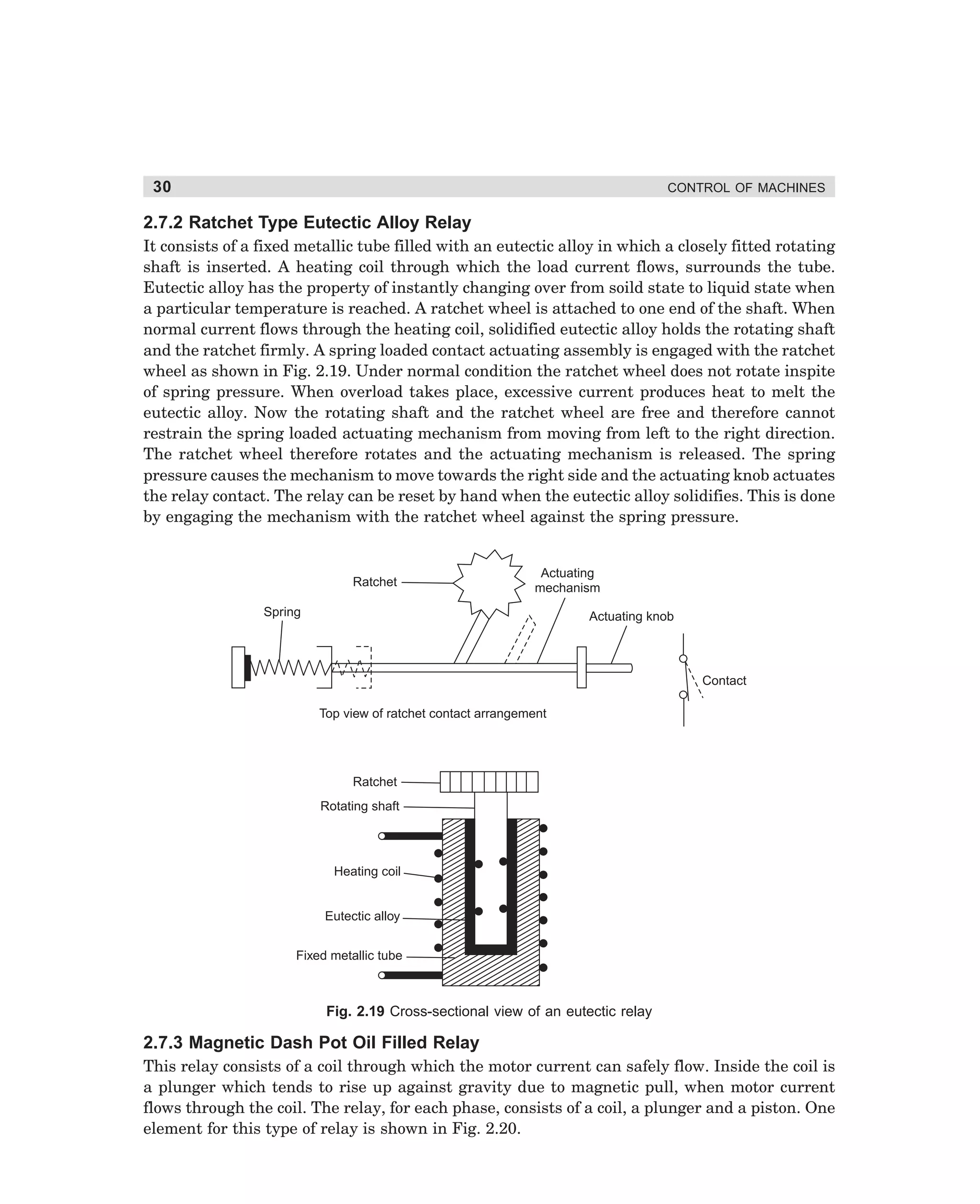
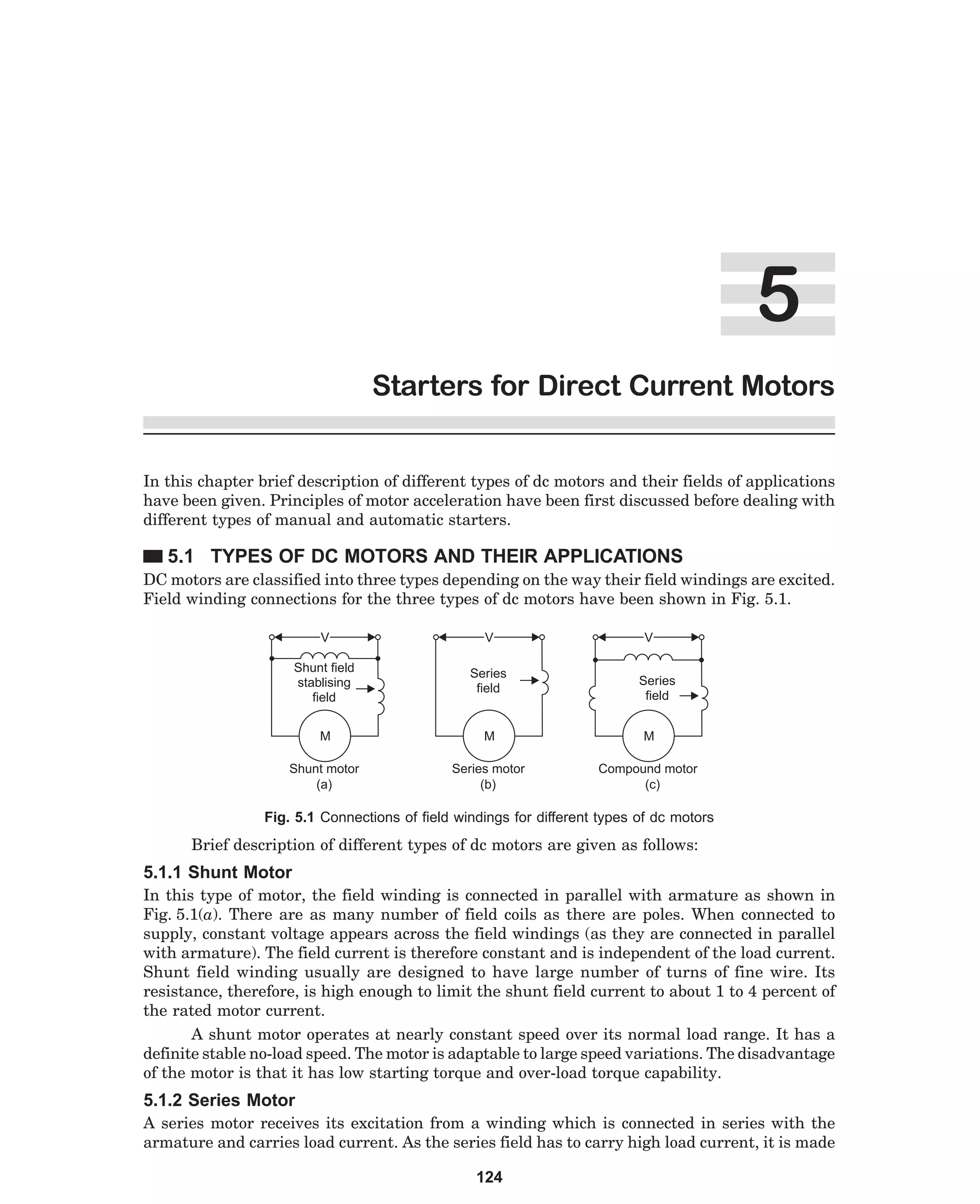
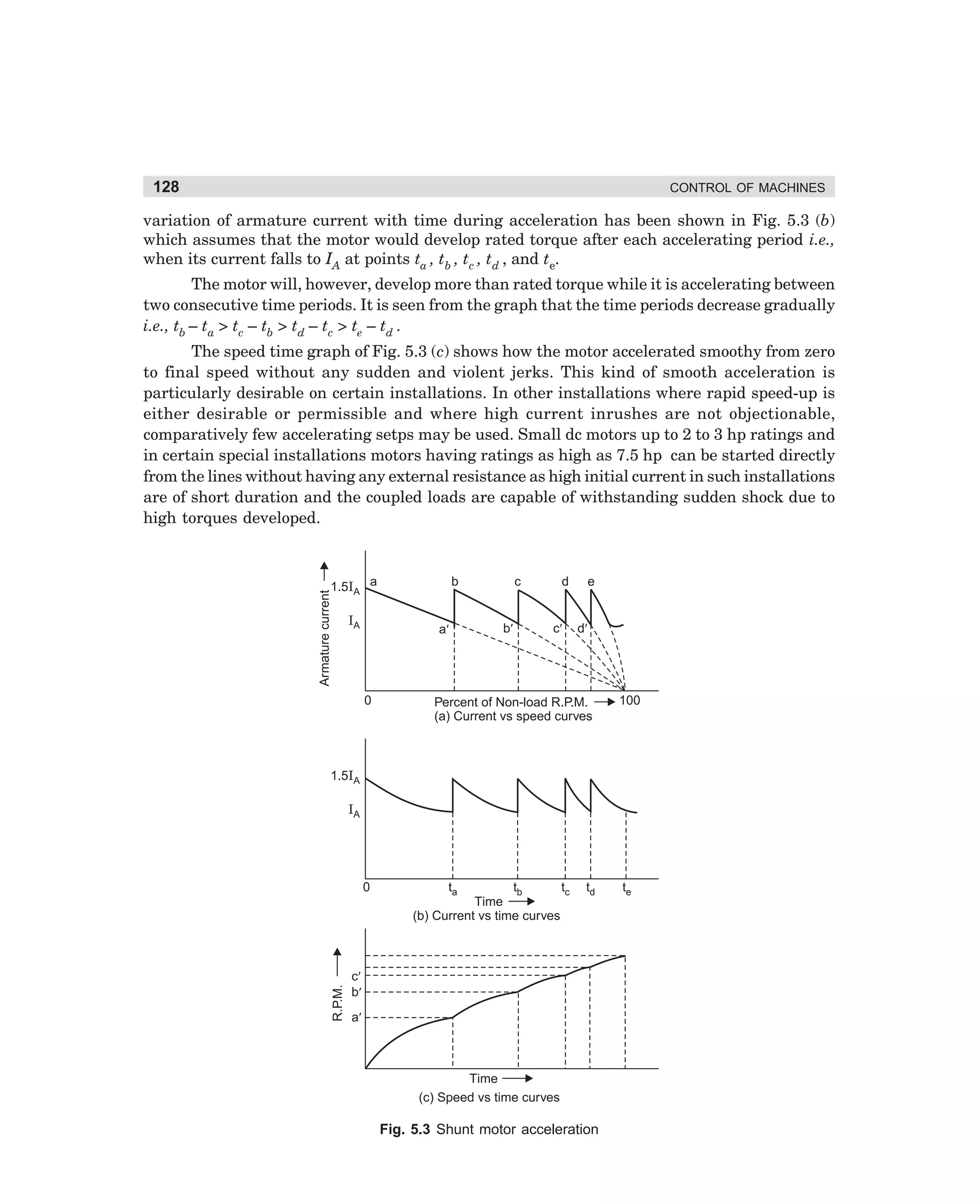
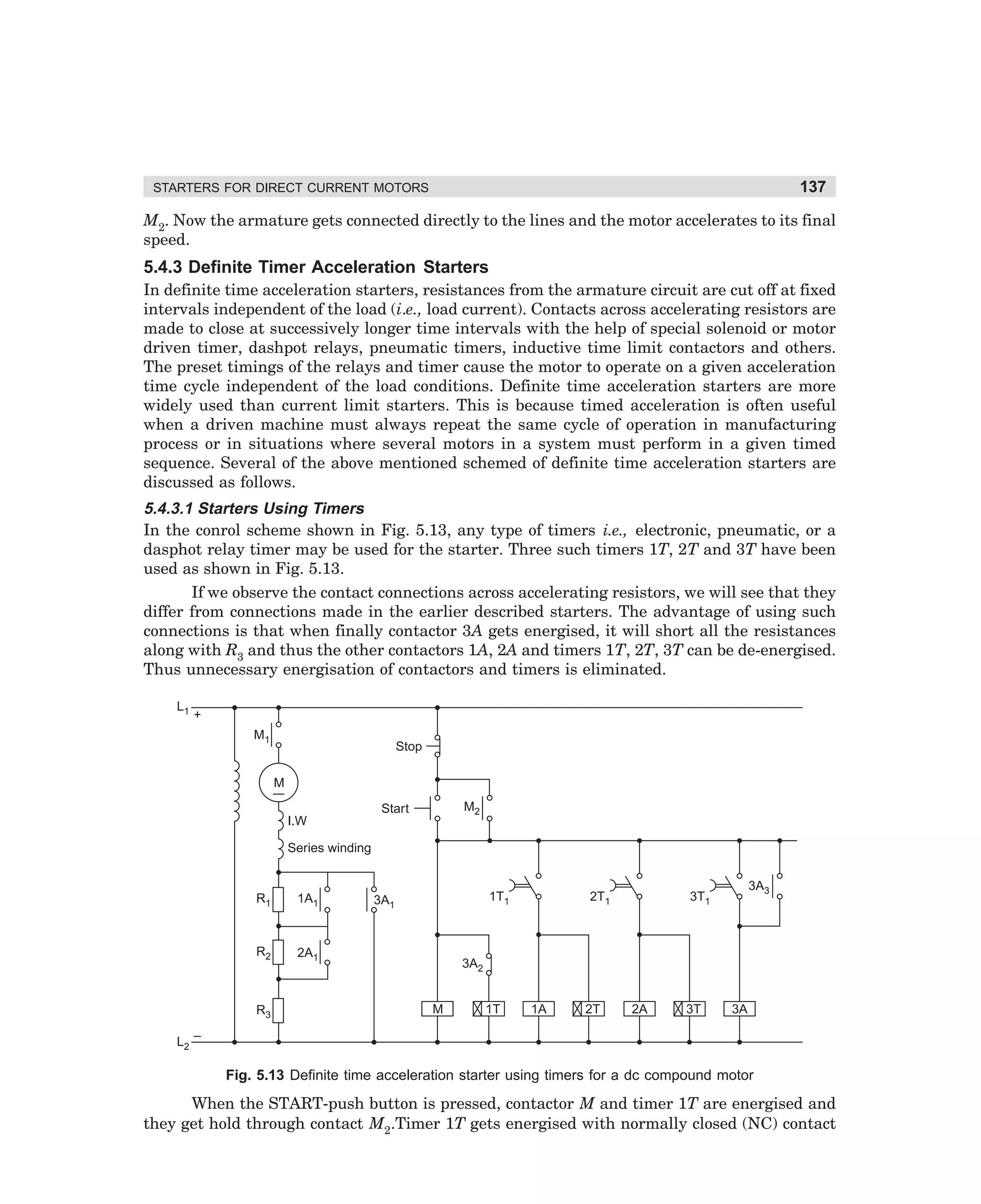
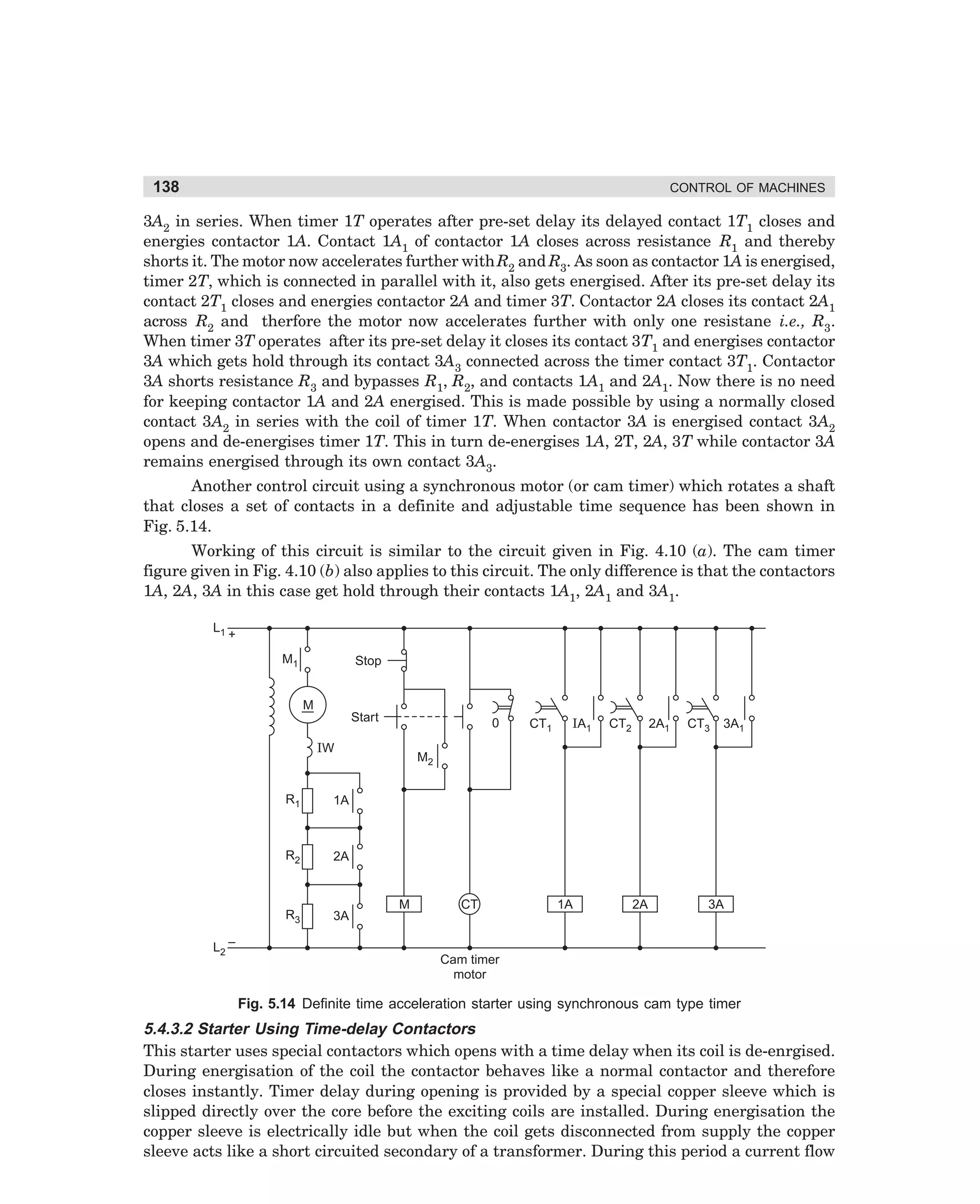
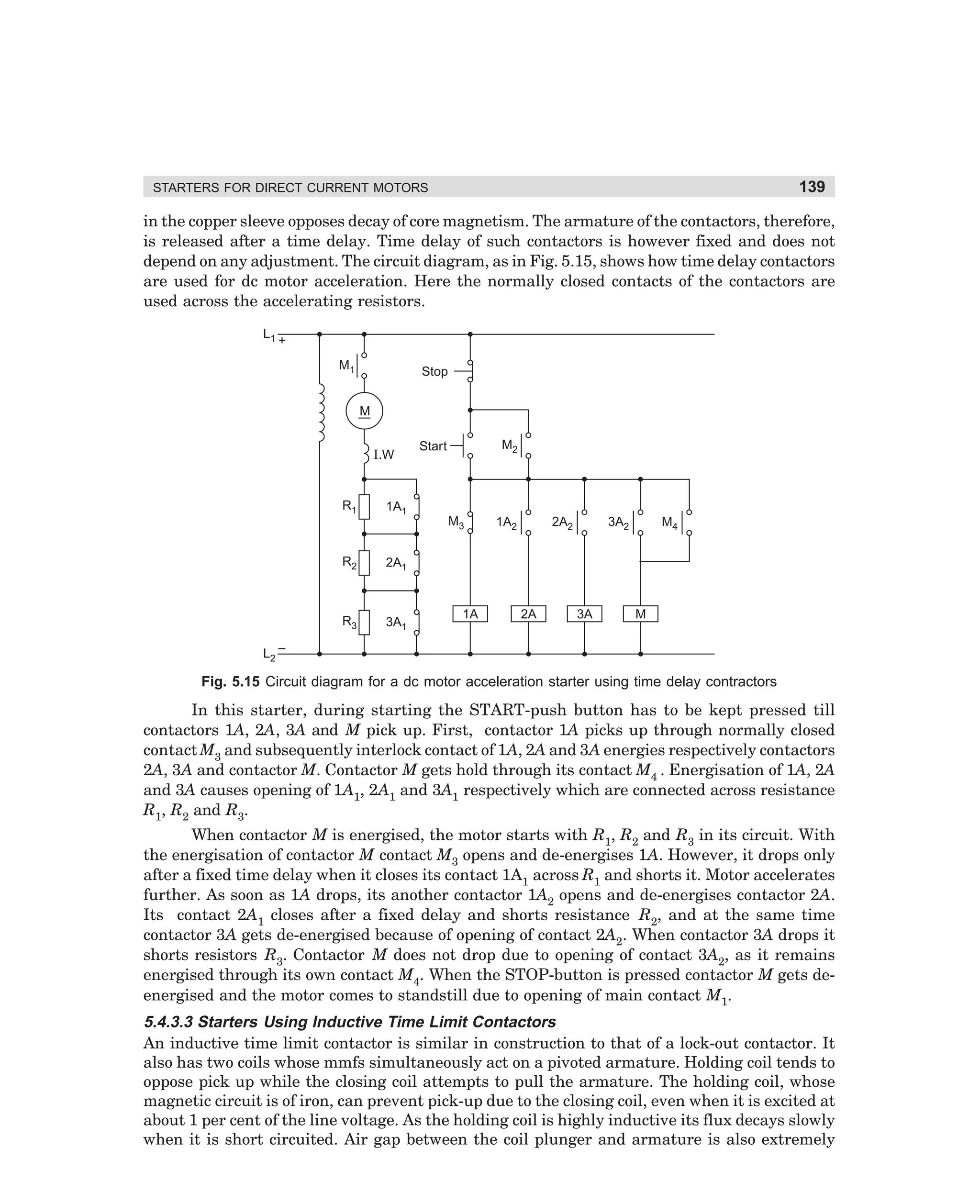
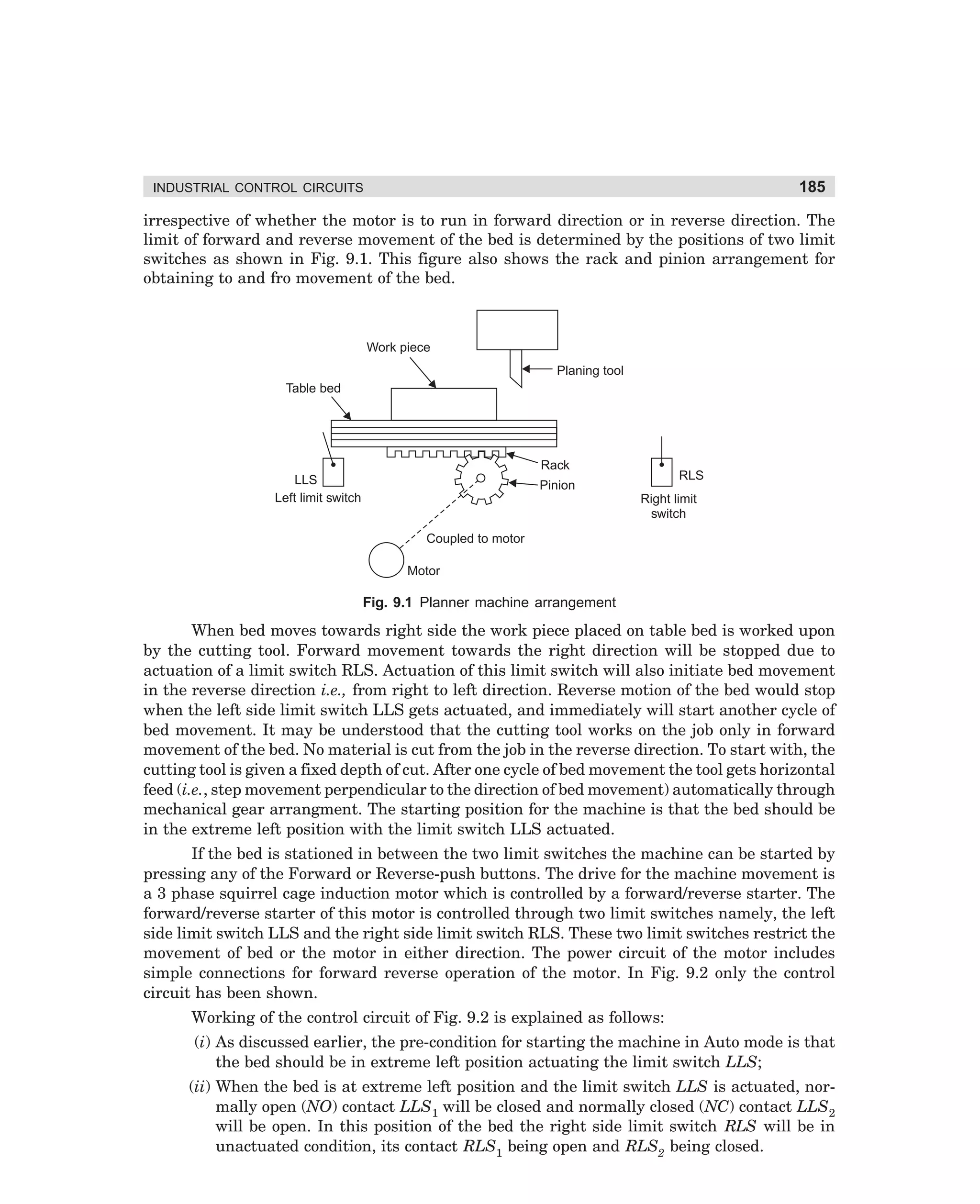
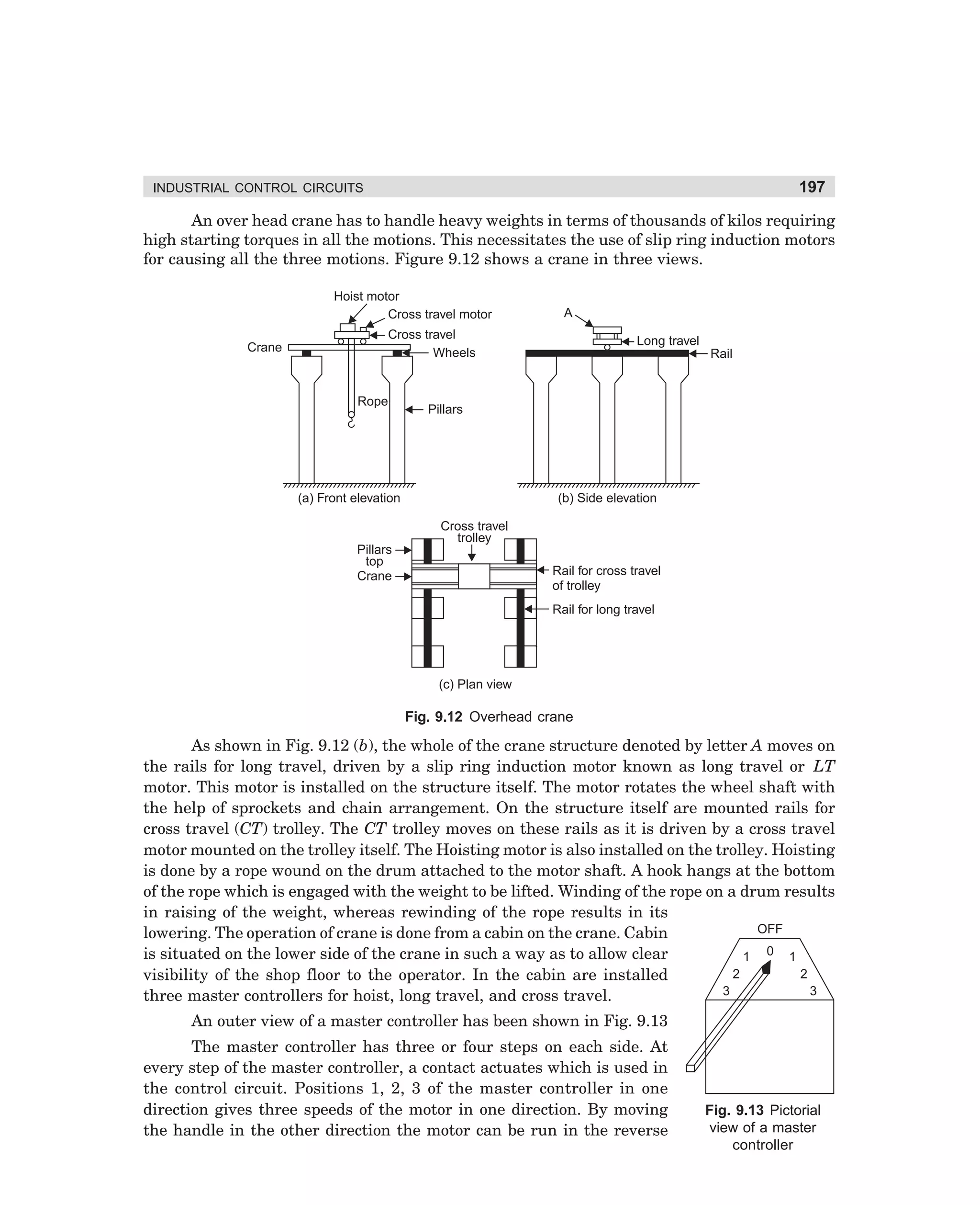
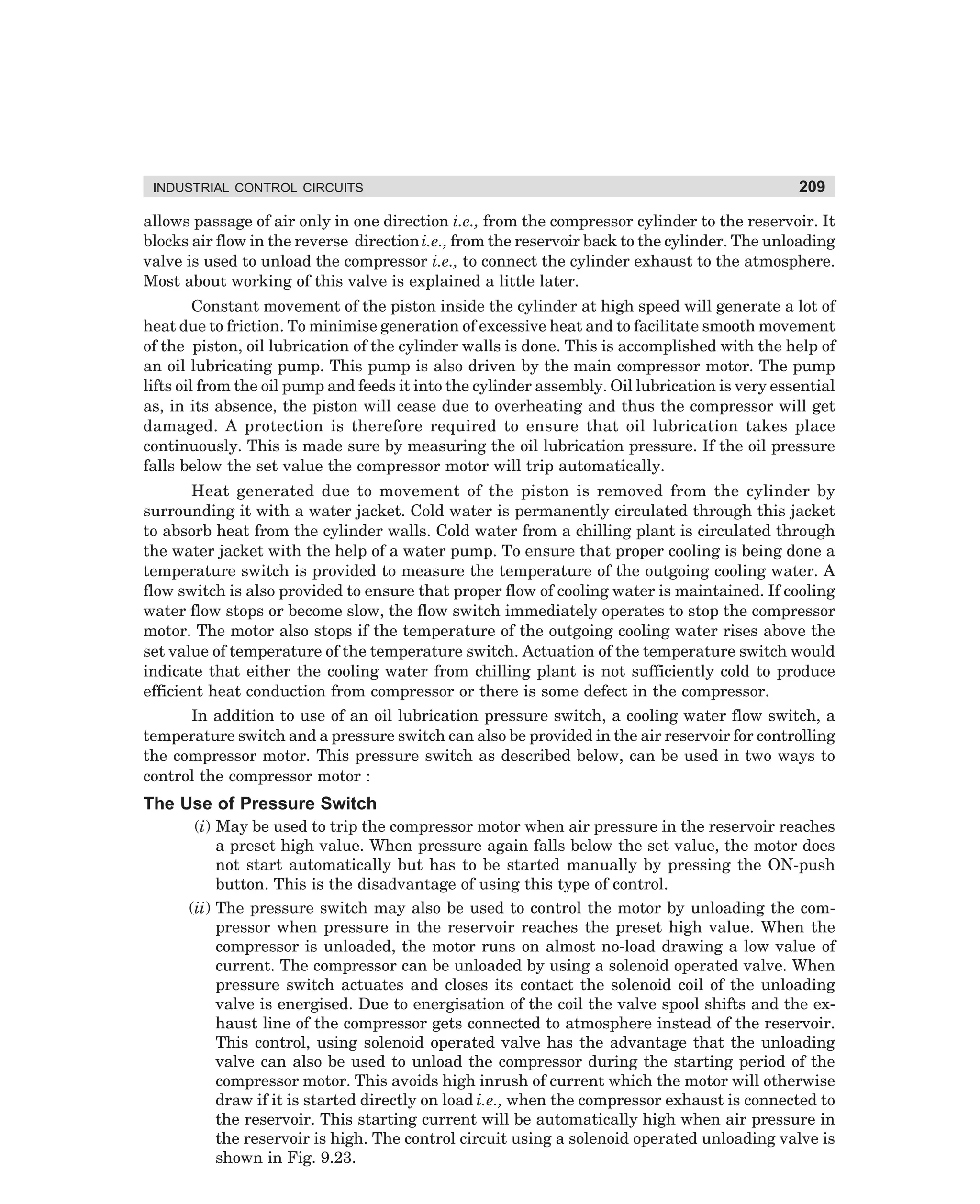
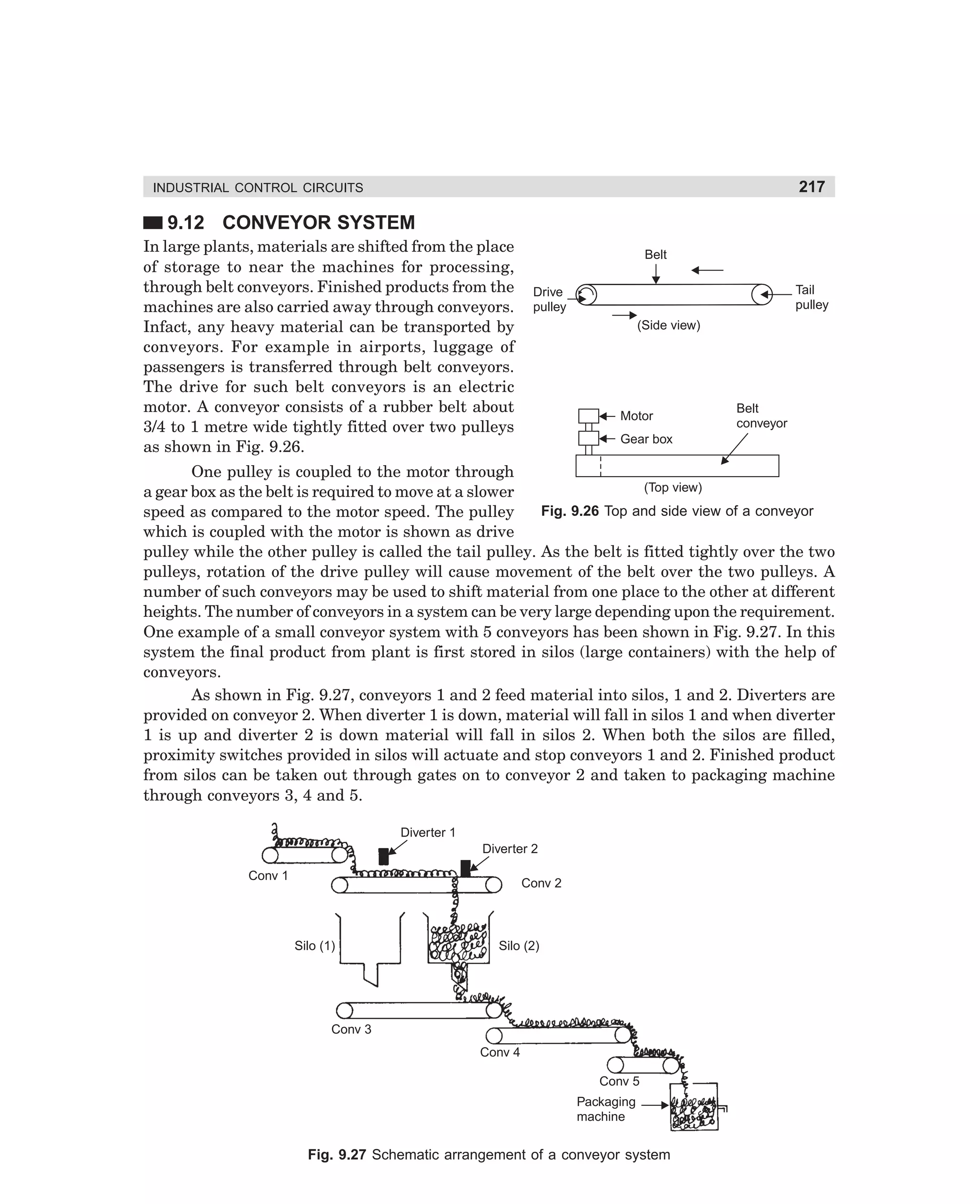
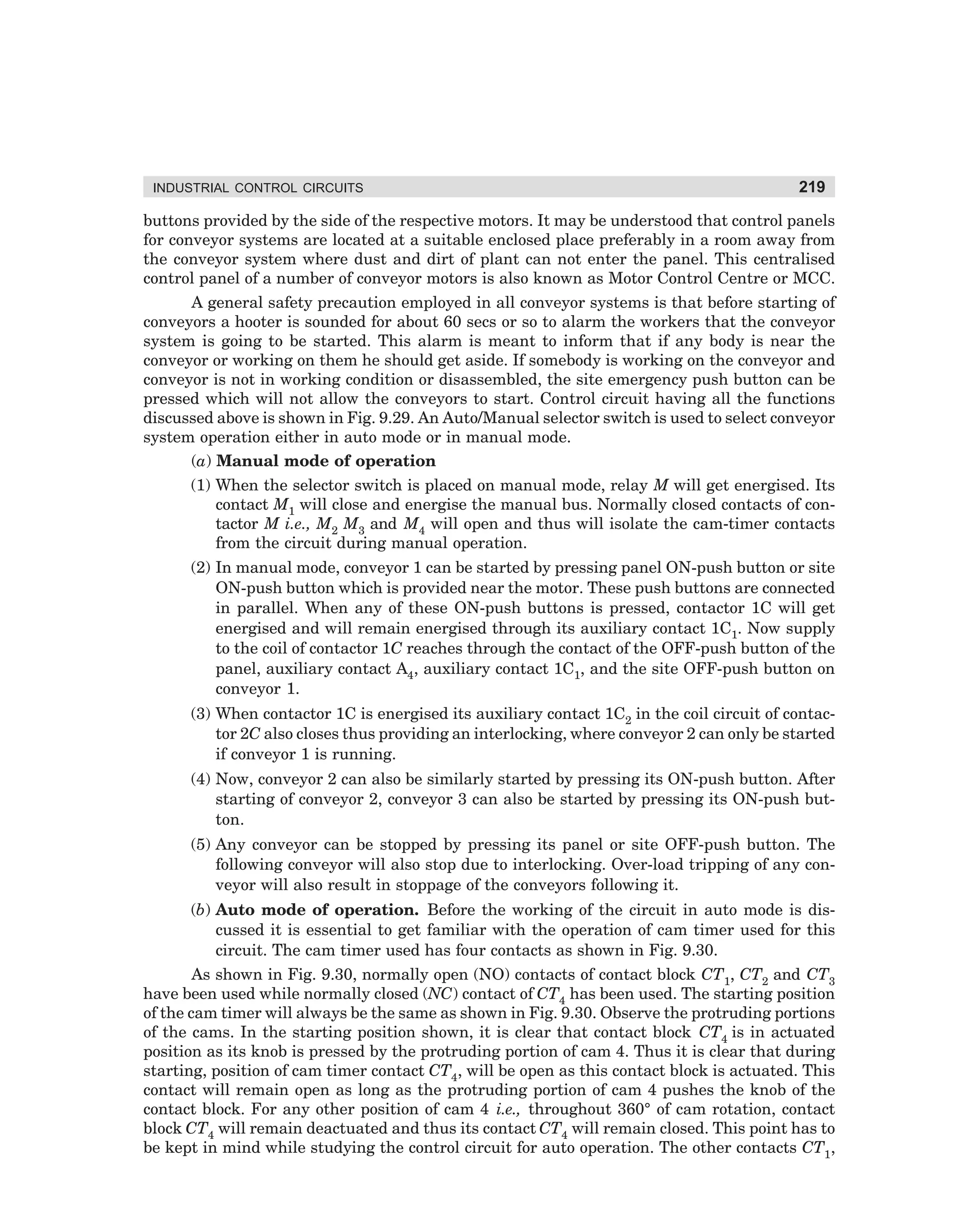
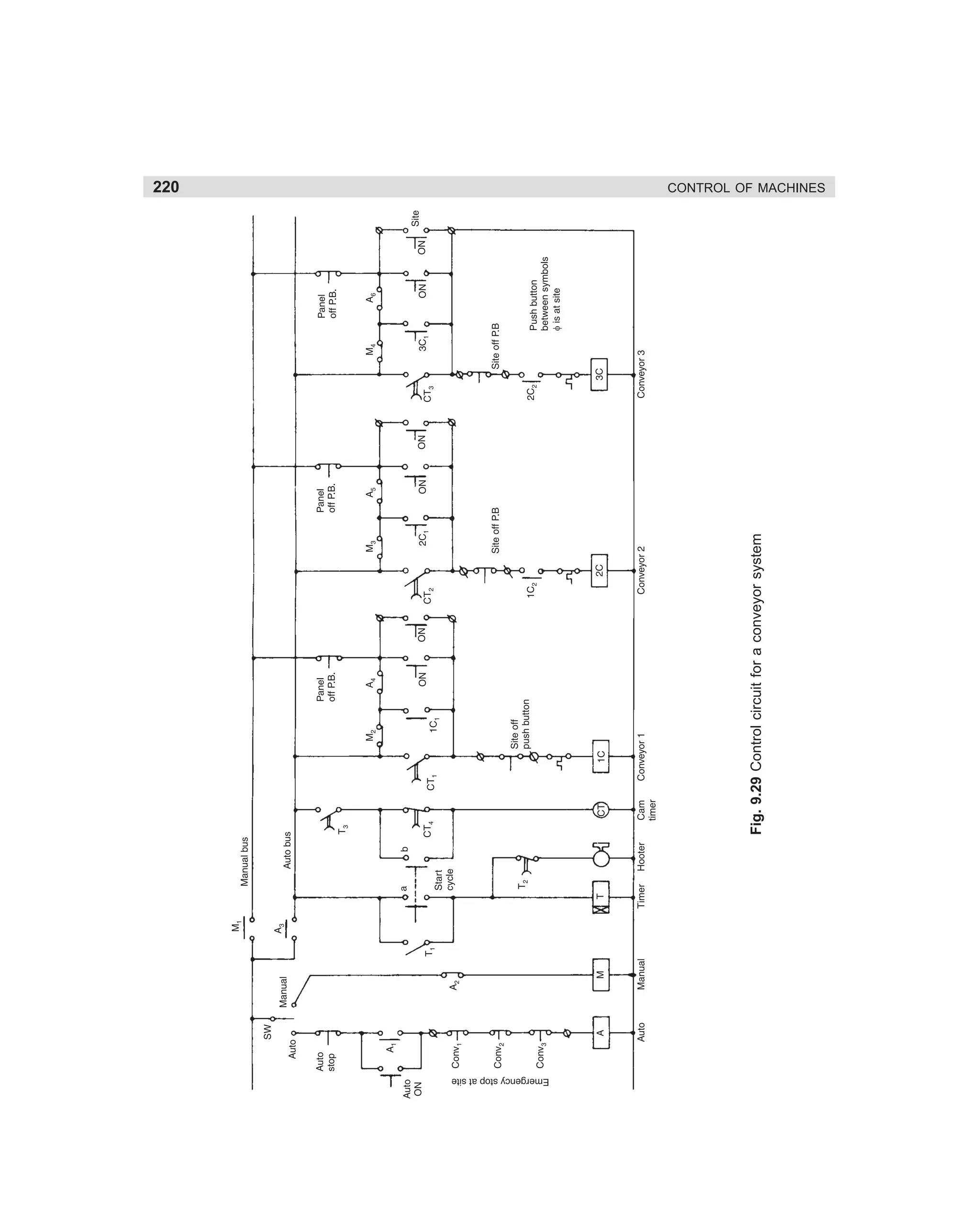
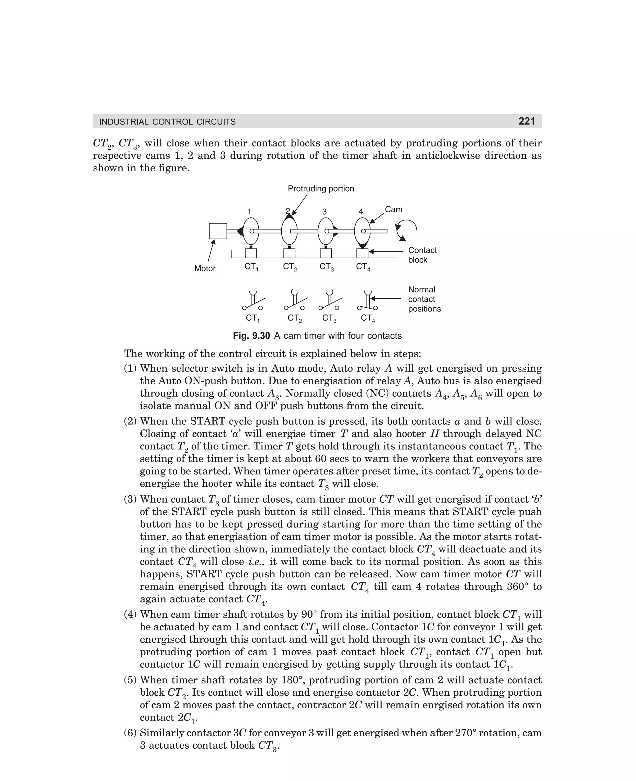
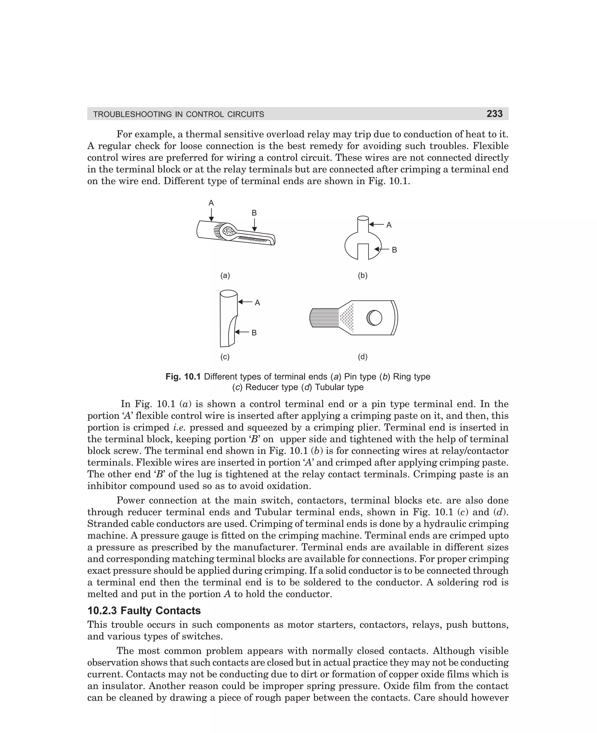
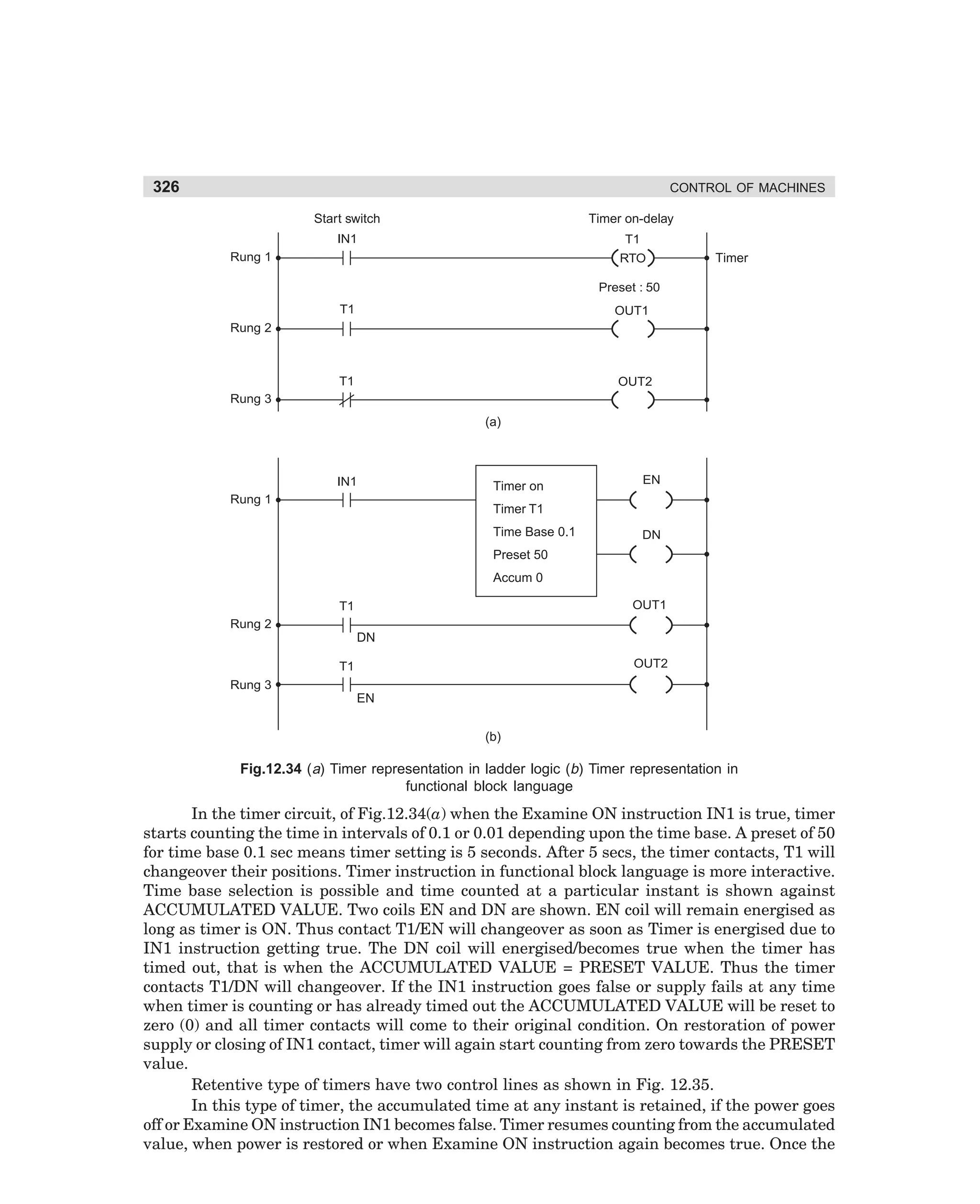
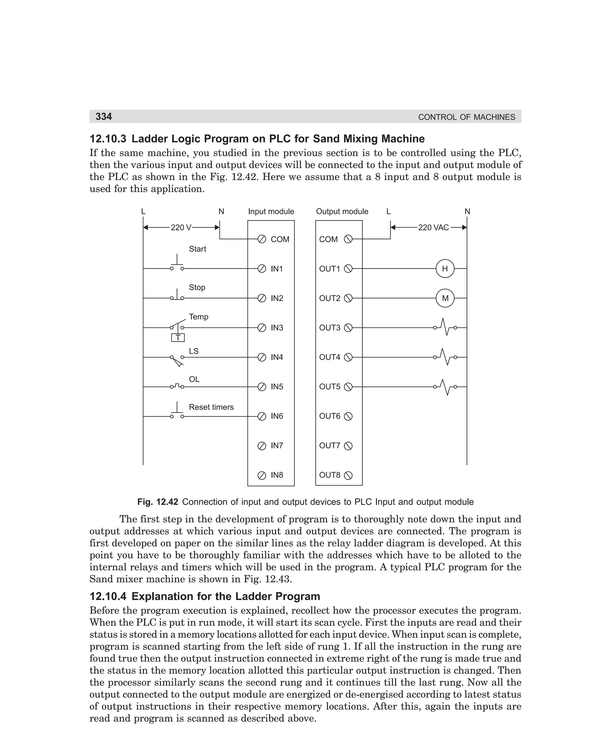
Downloaded 121 times


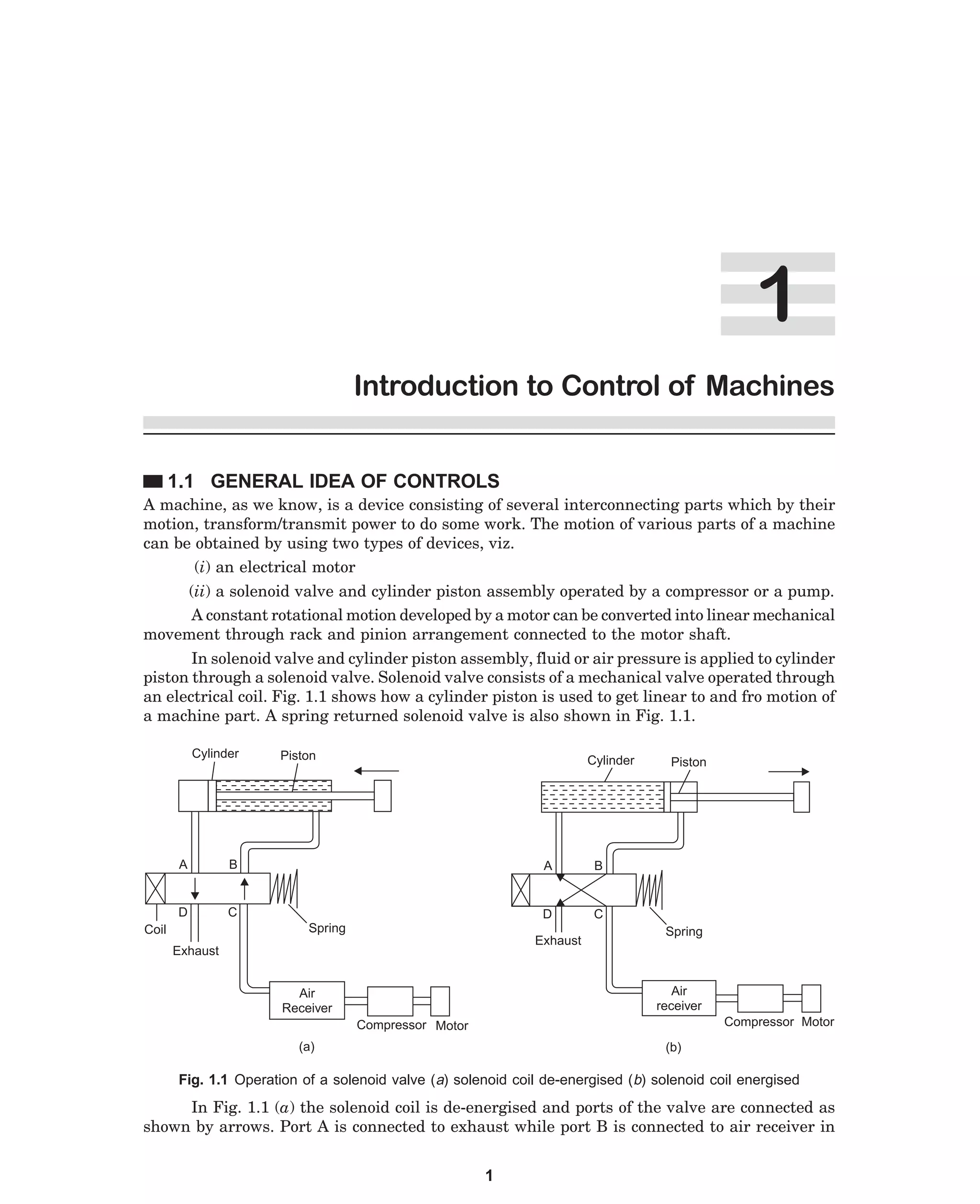
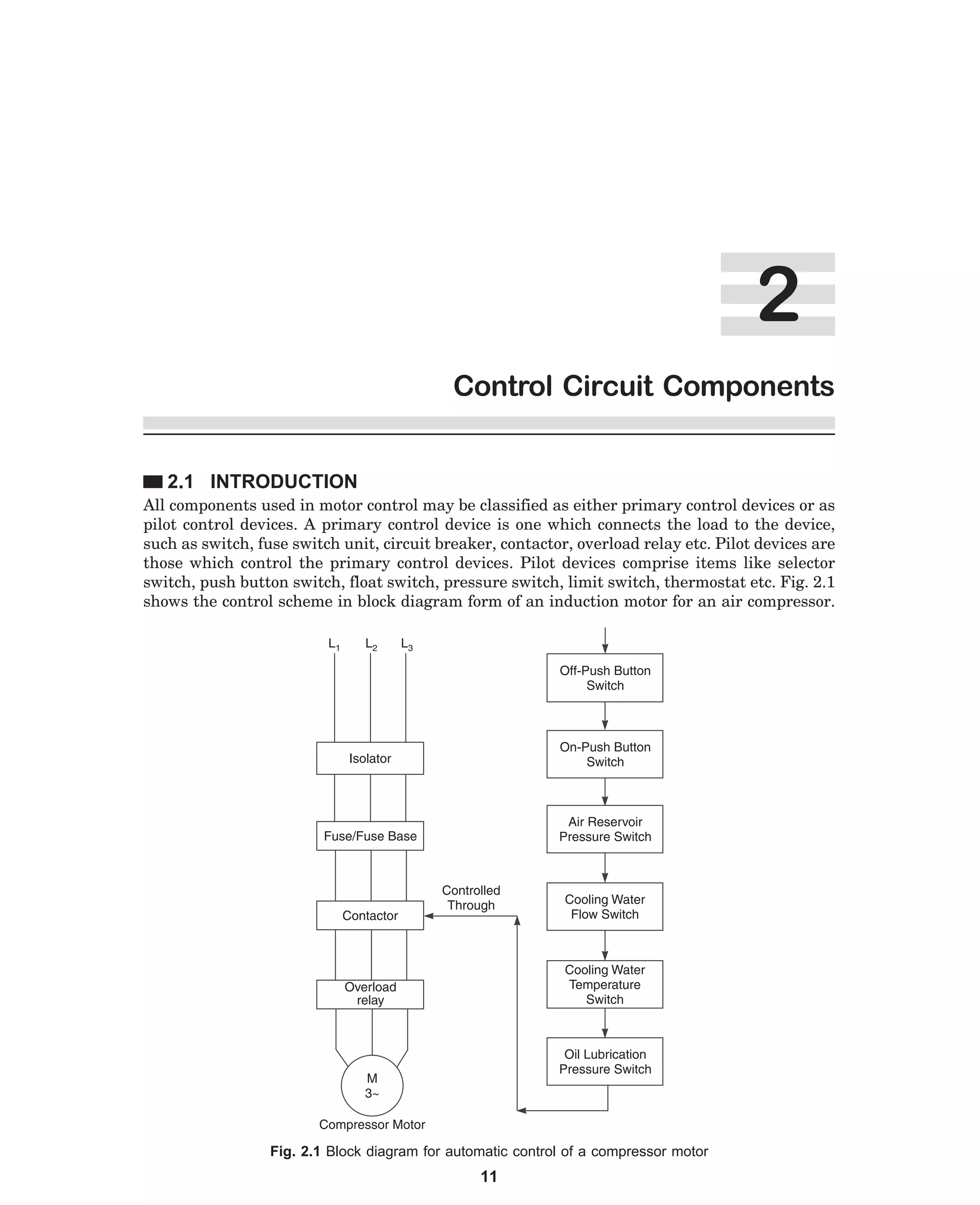
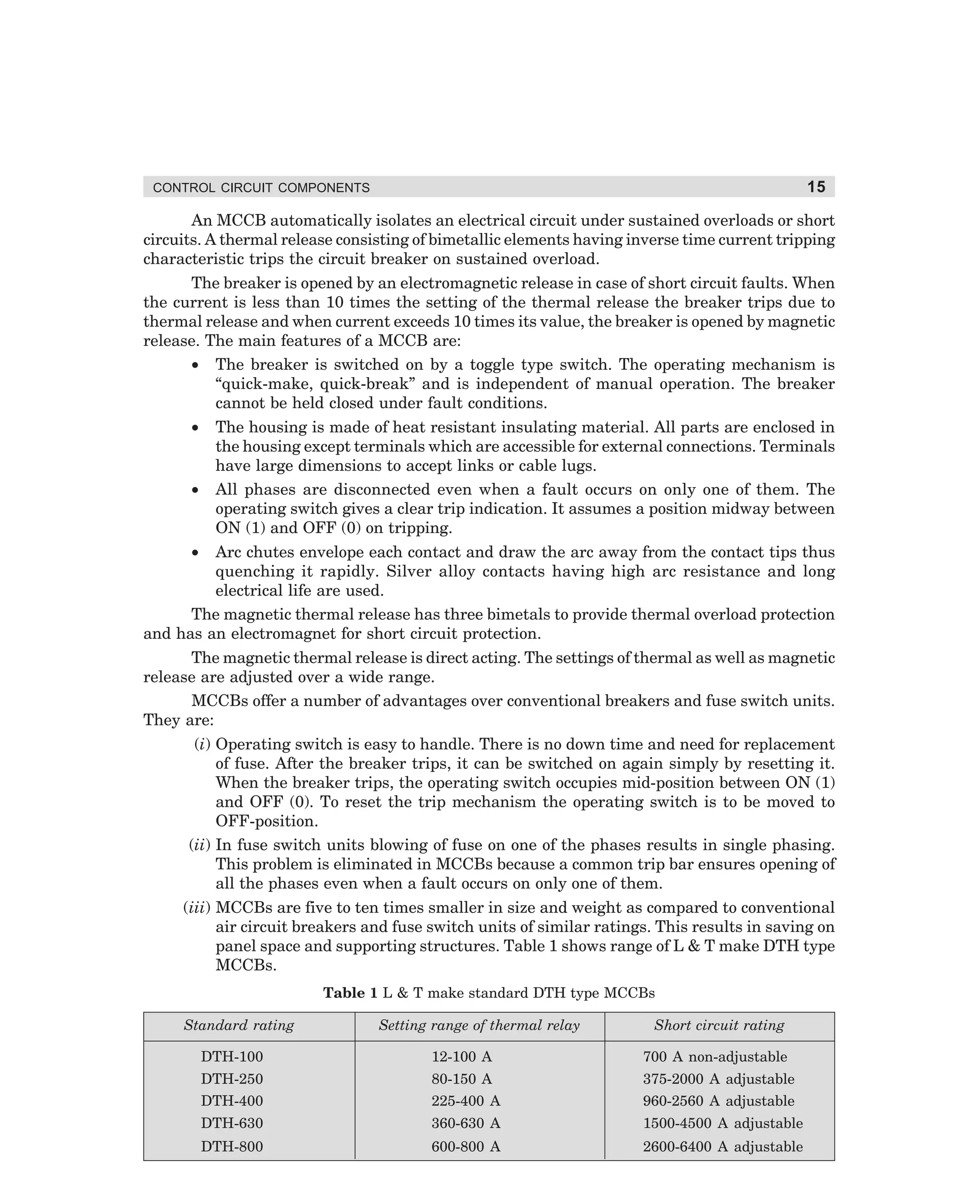

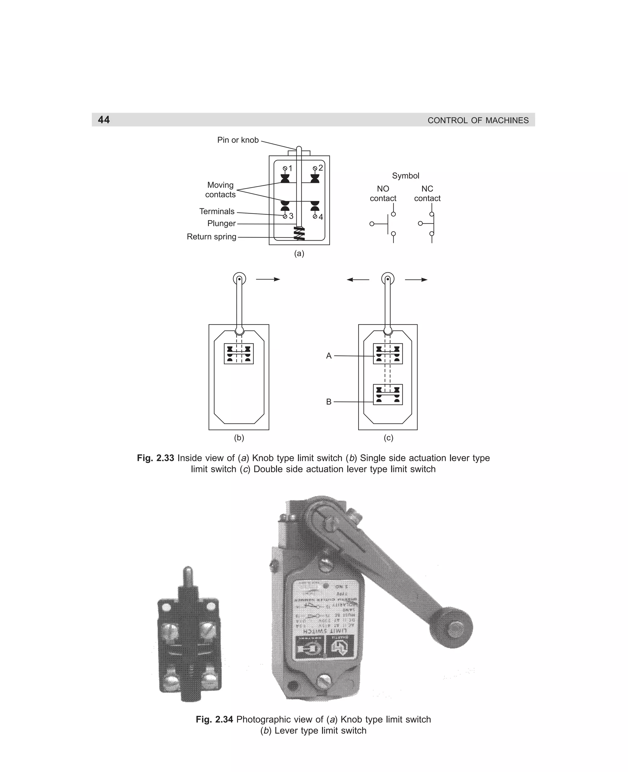


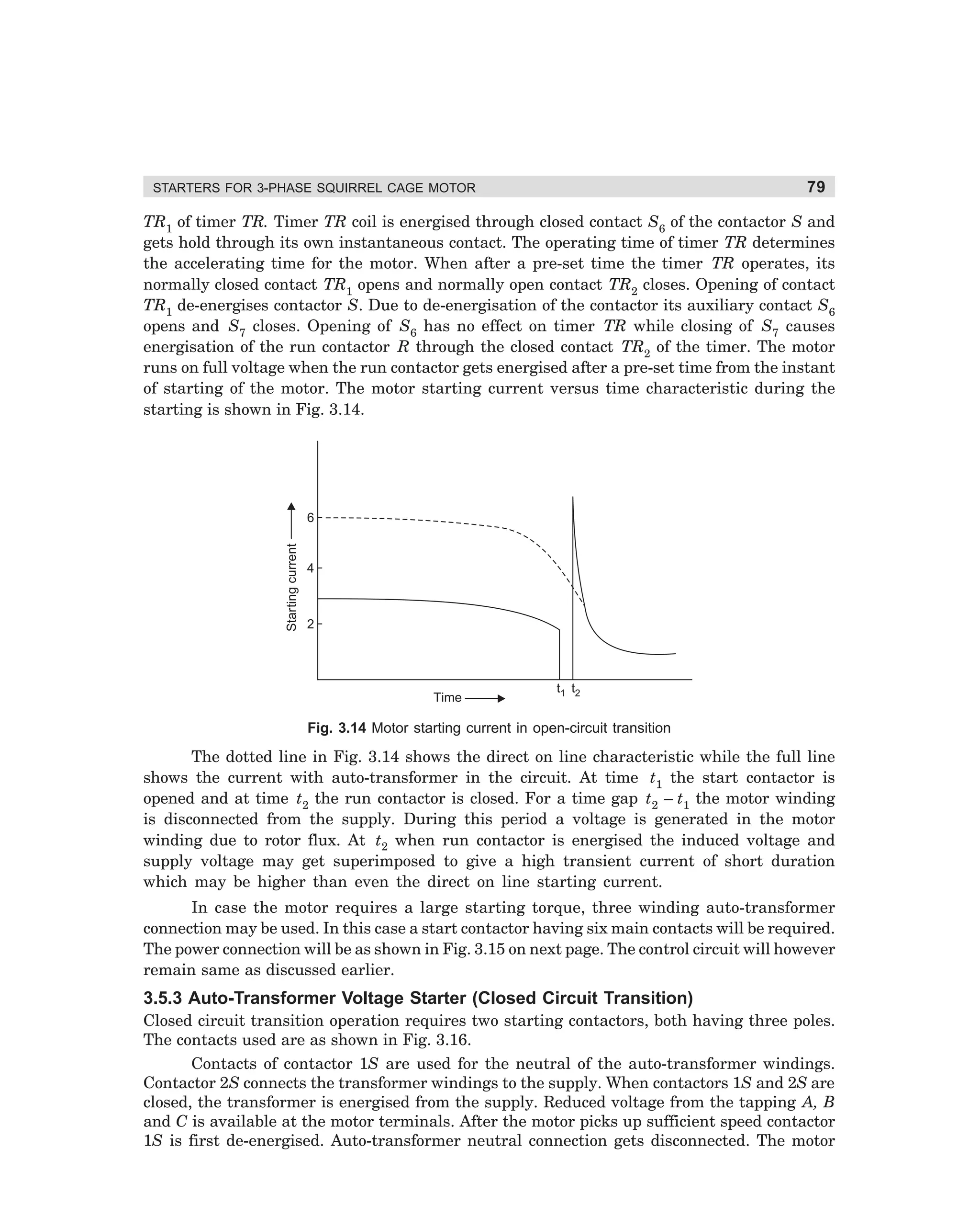
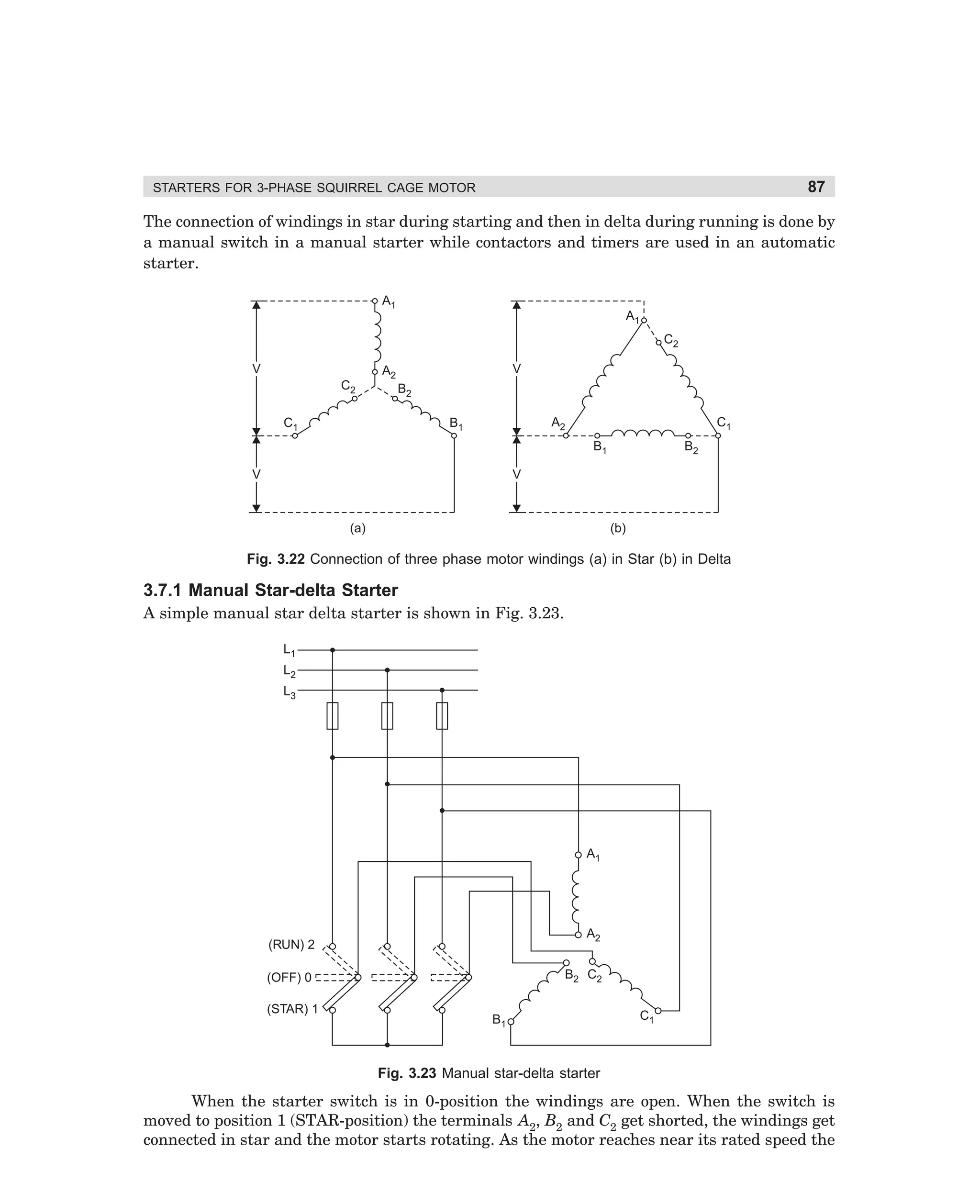
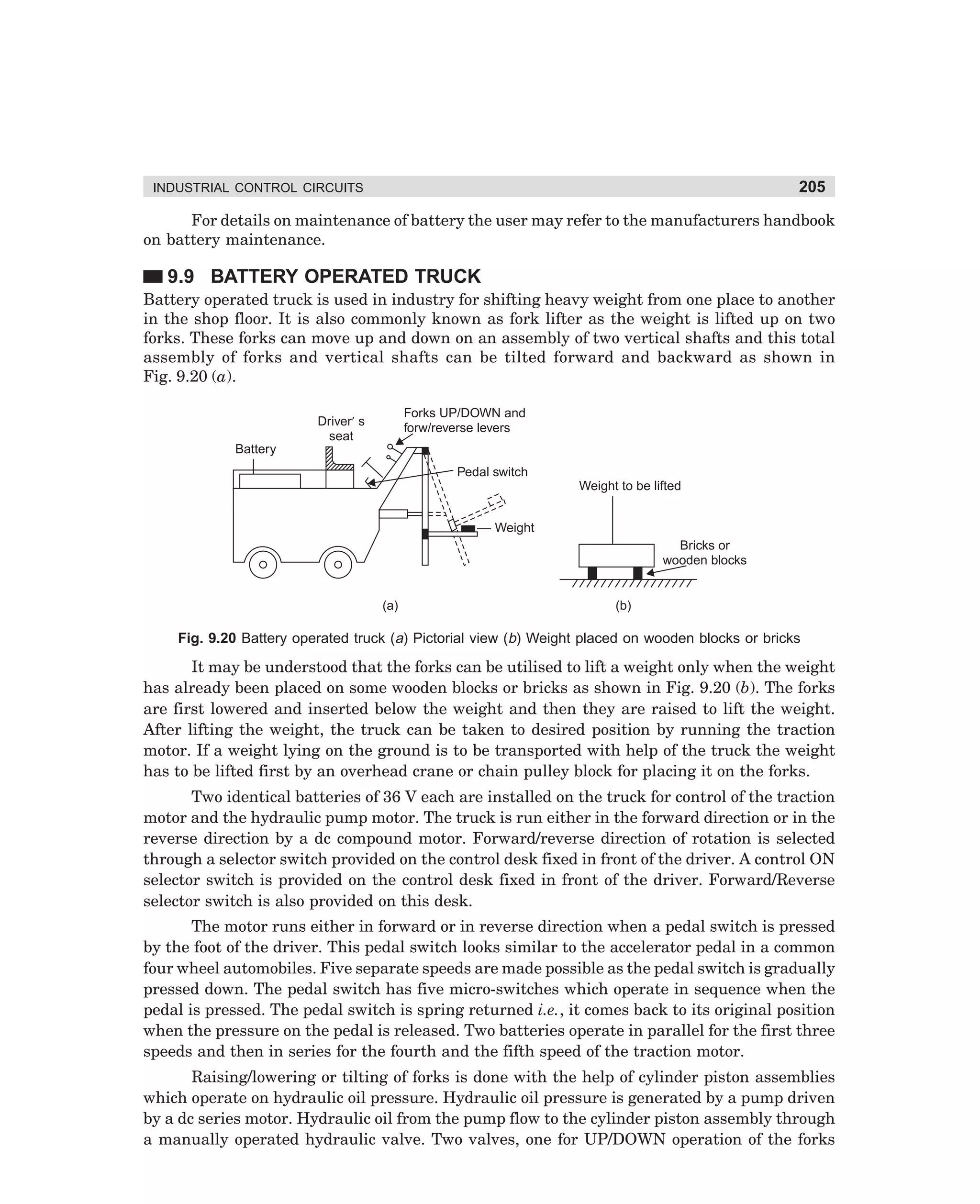
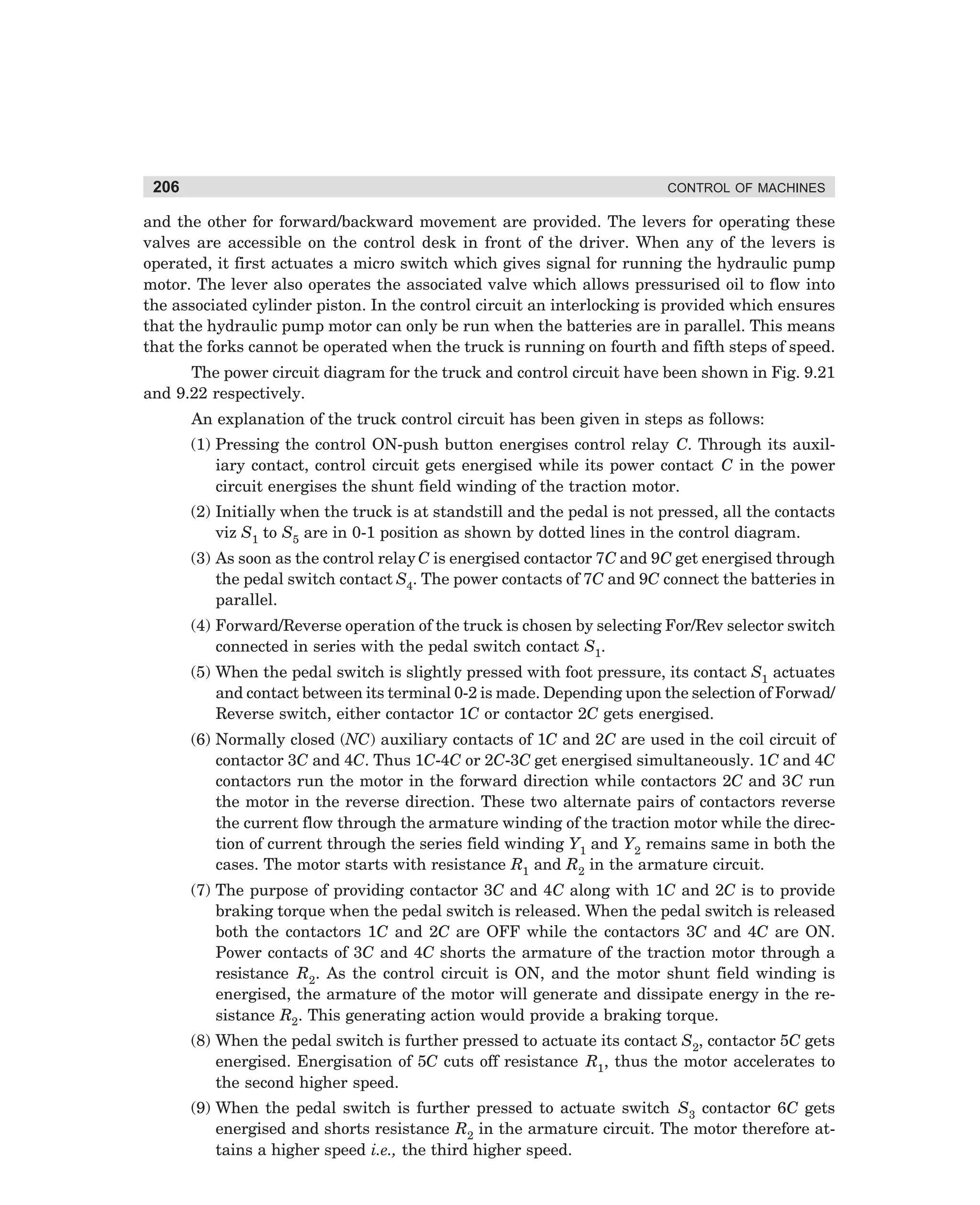
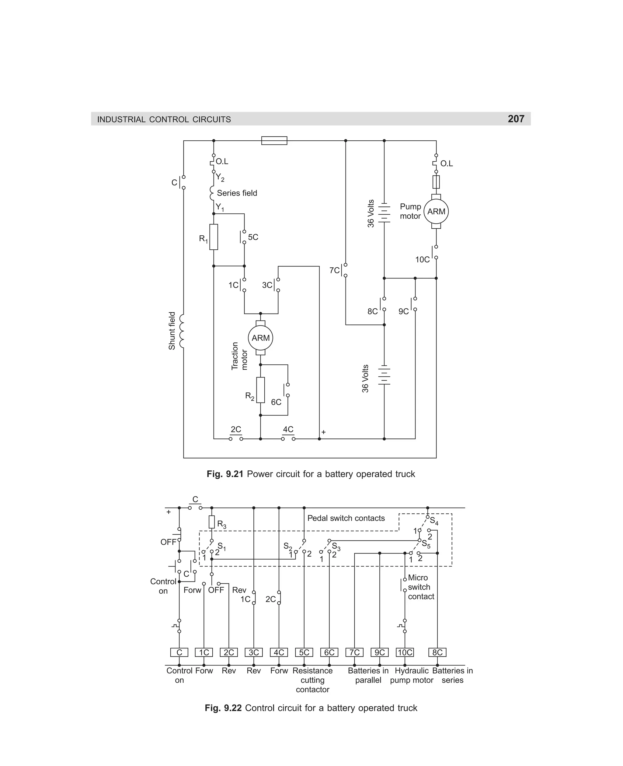
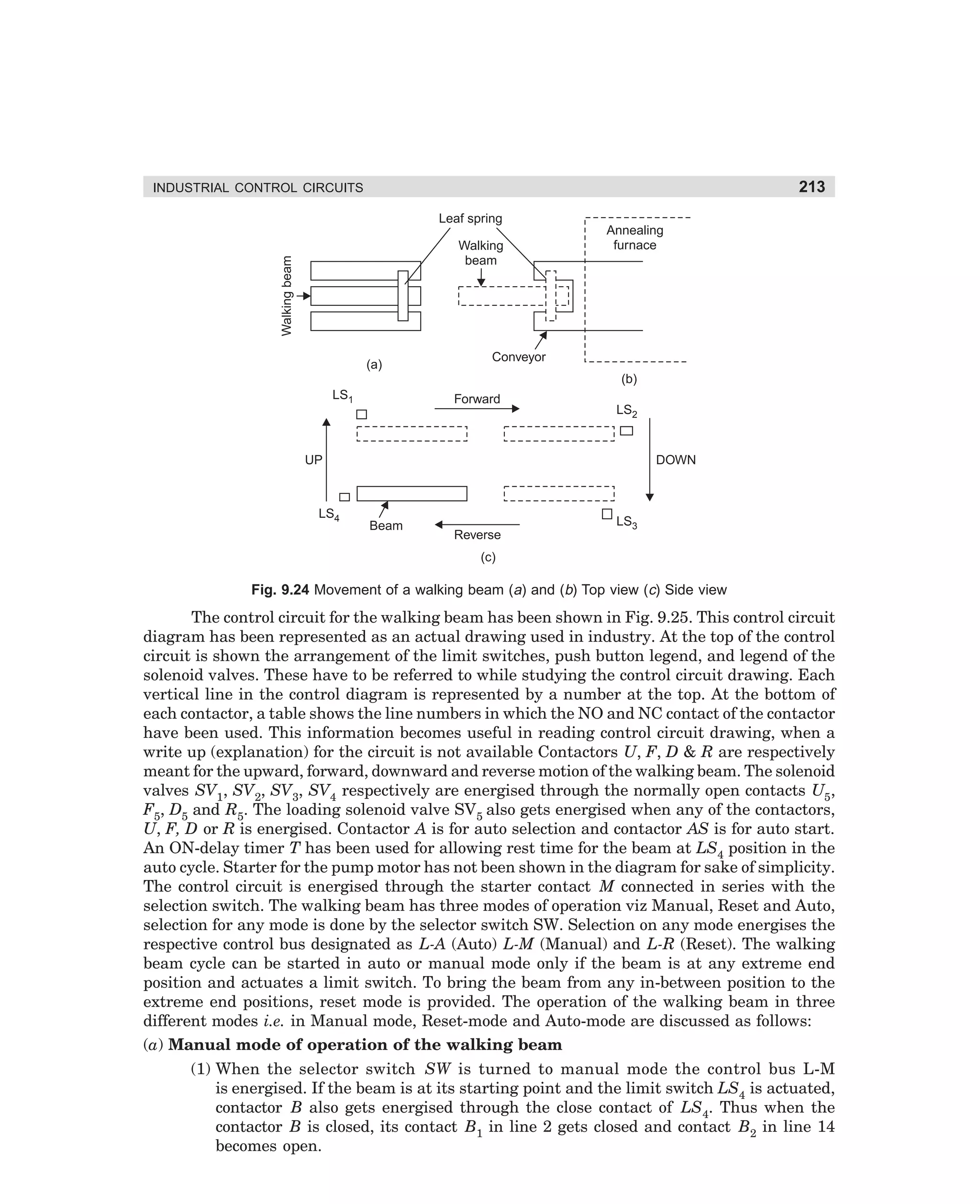
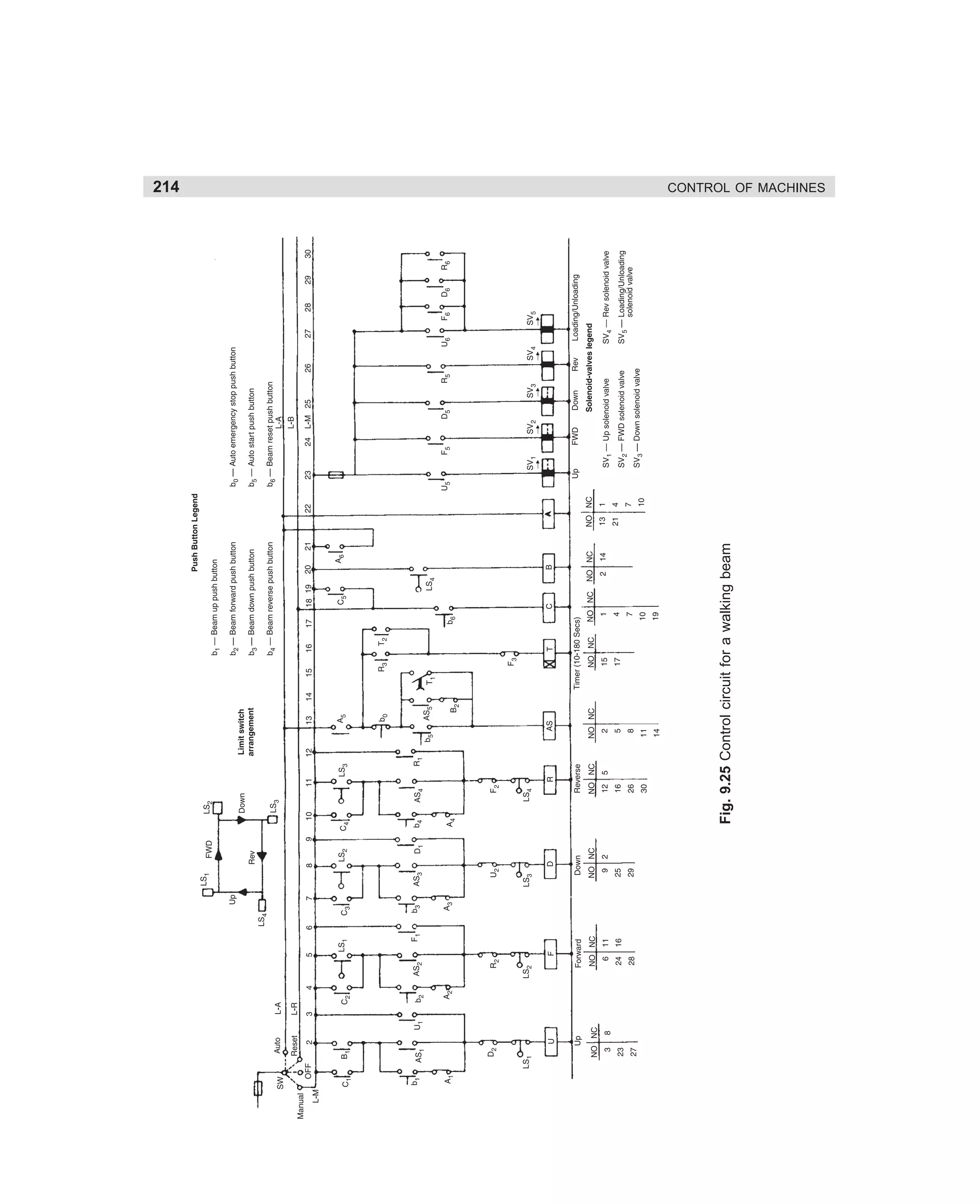
![71
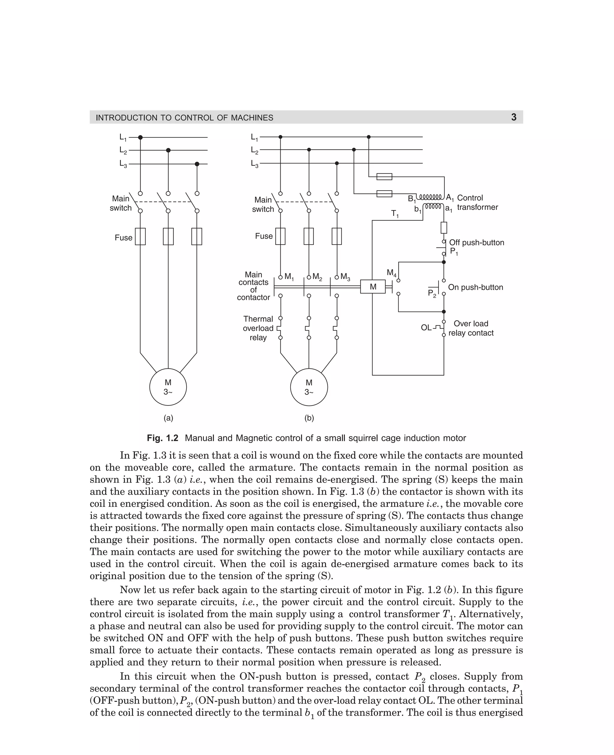
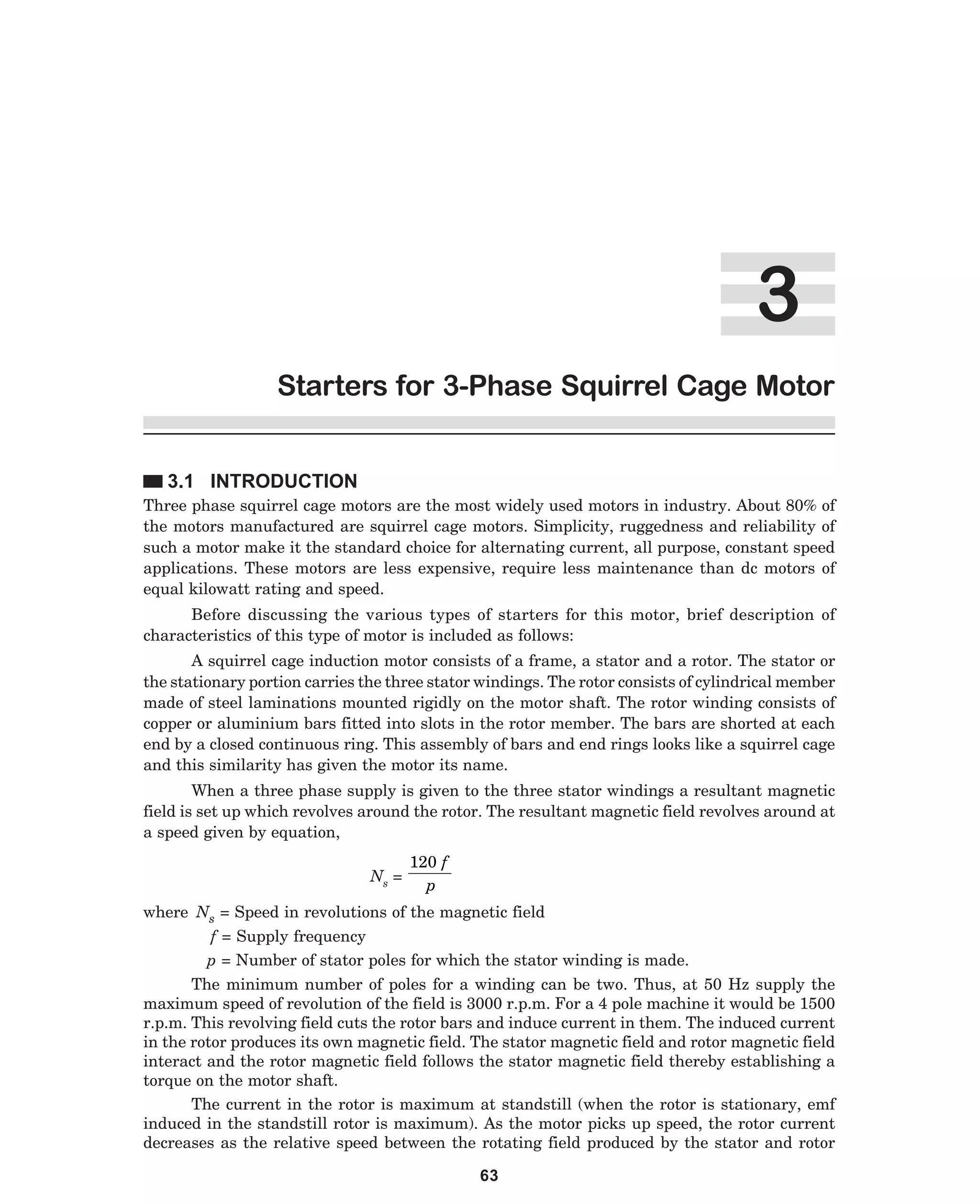
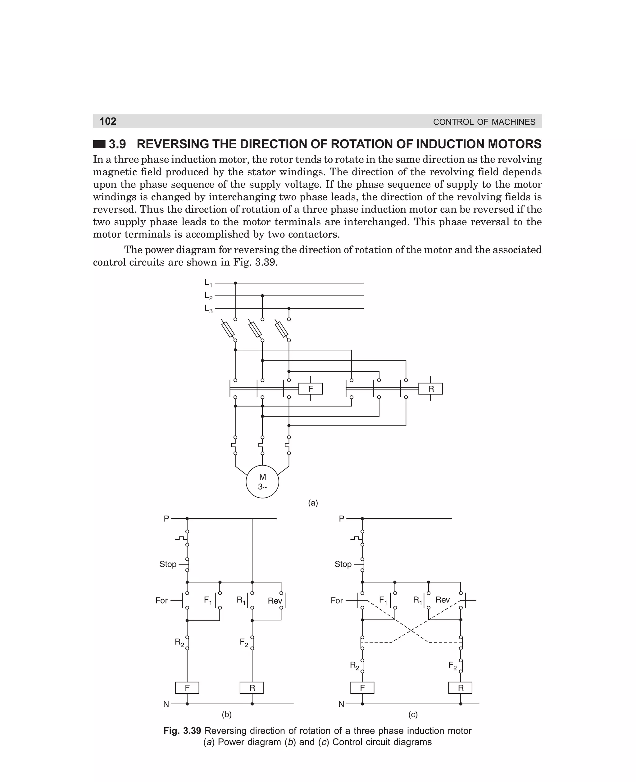
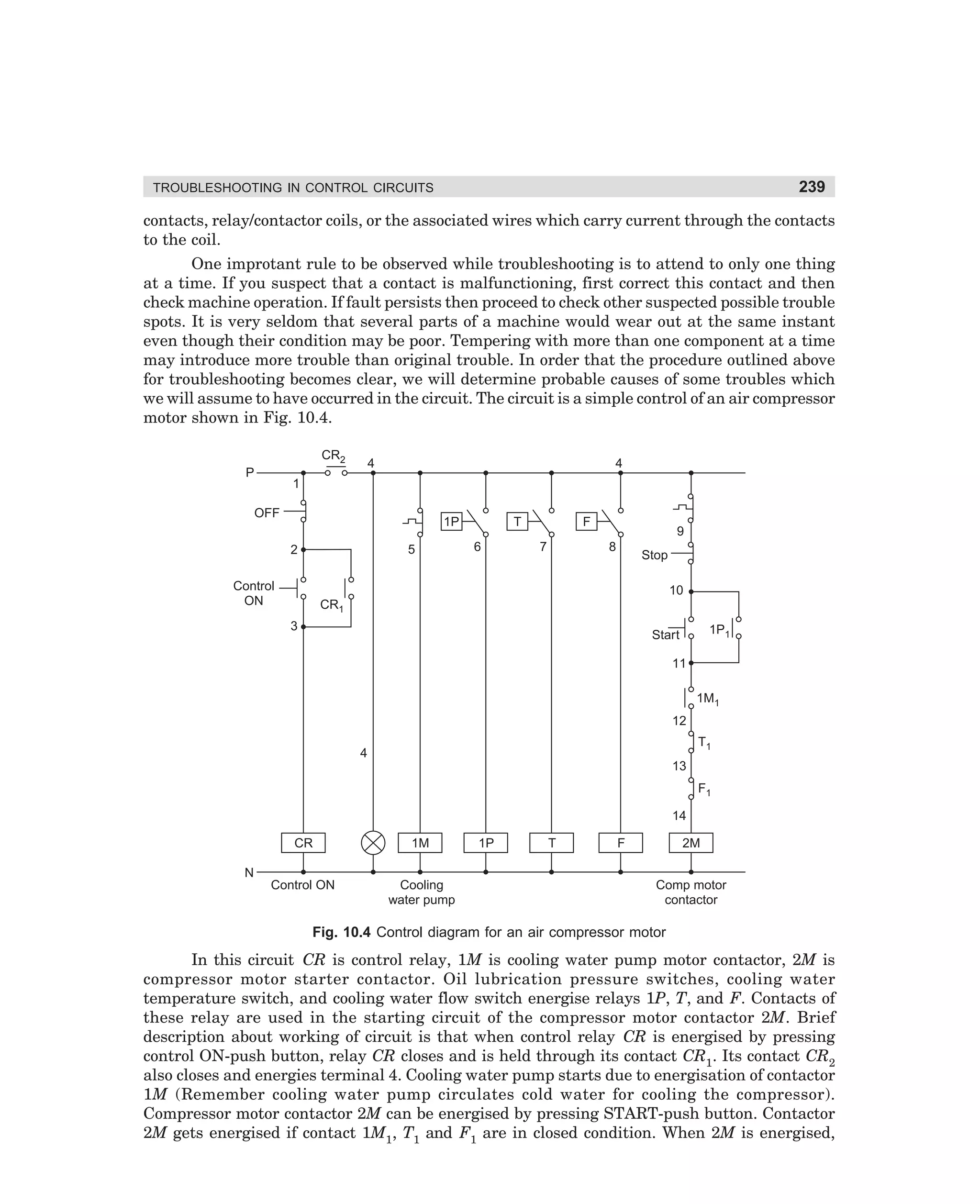
STARTERS FOR 3-PHASE SQUIRREL CAGE MOTOR
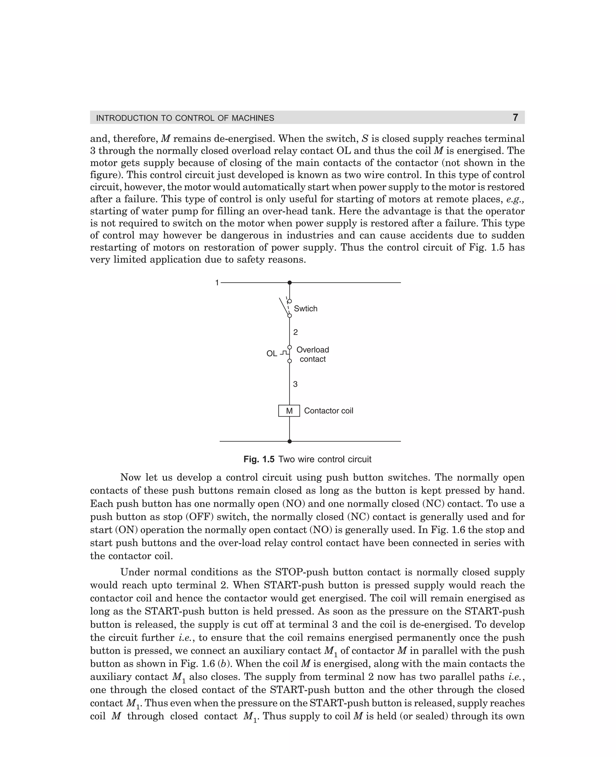
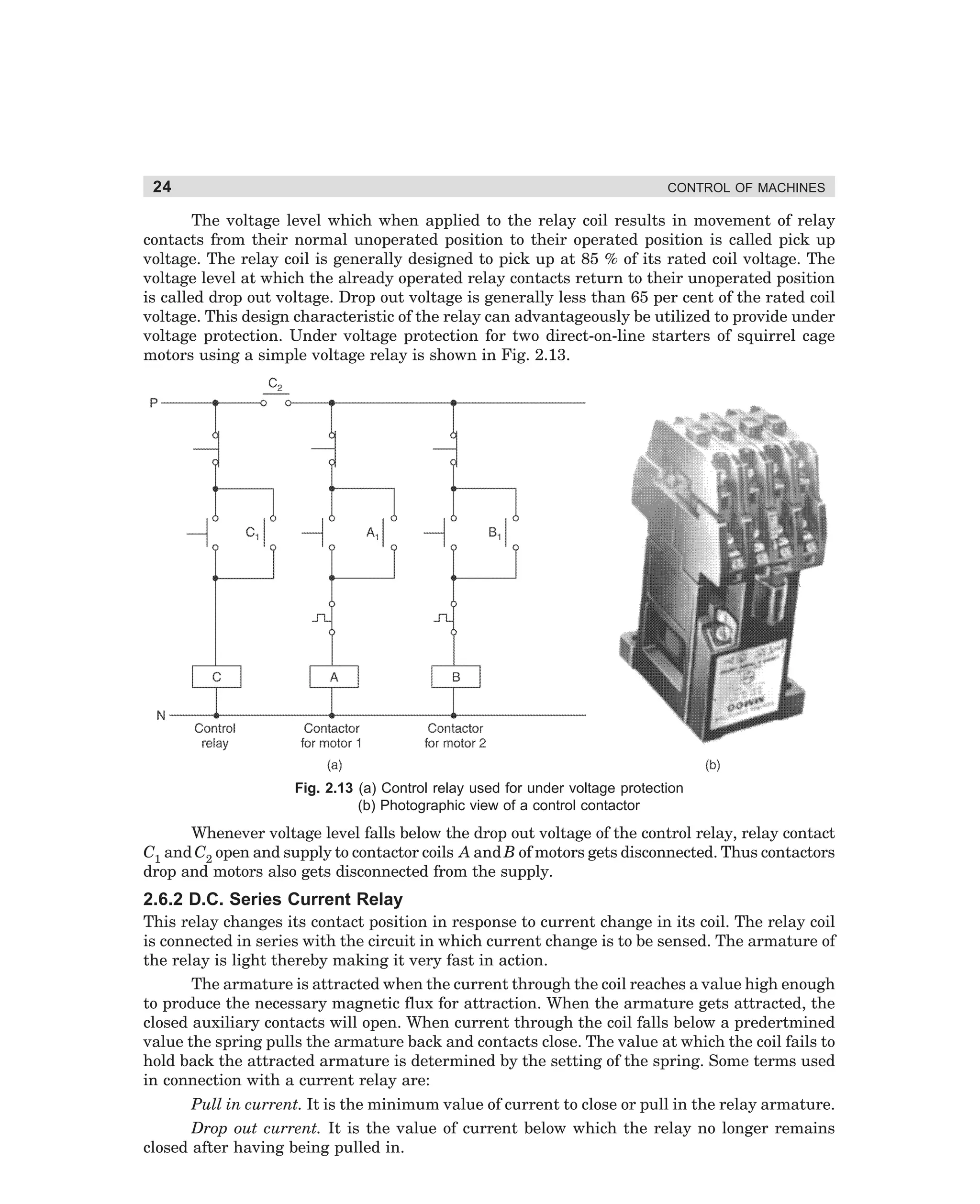
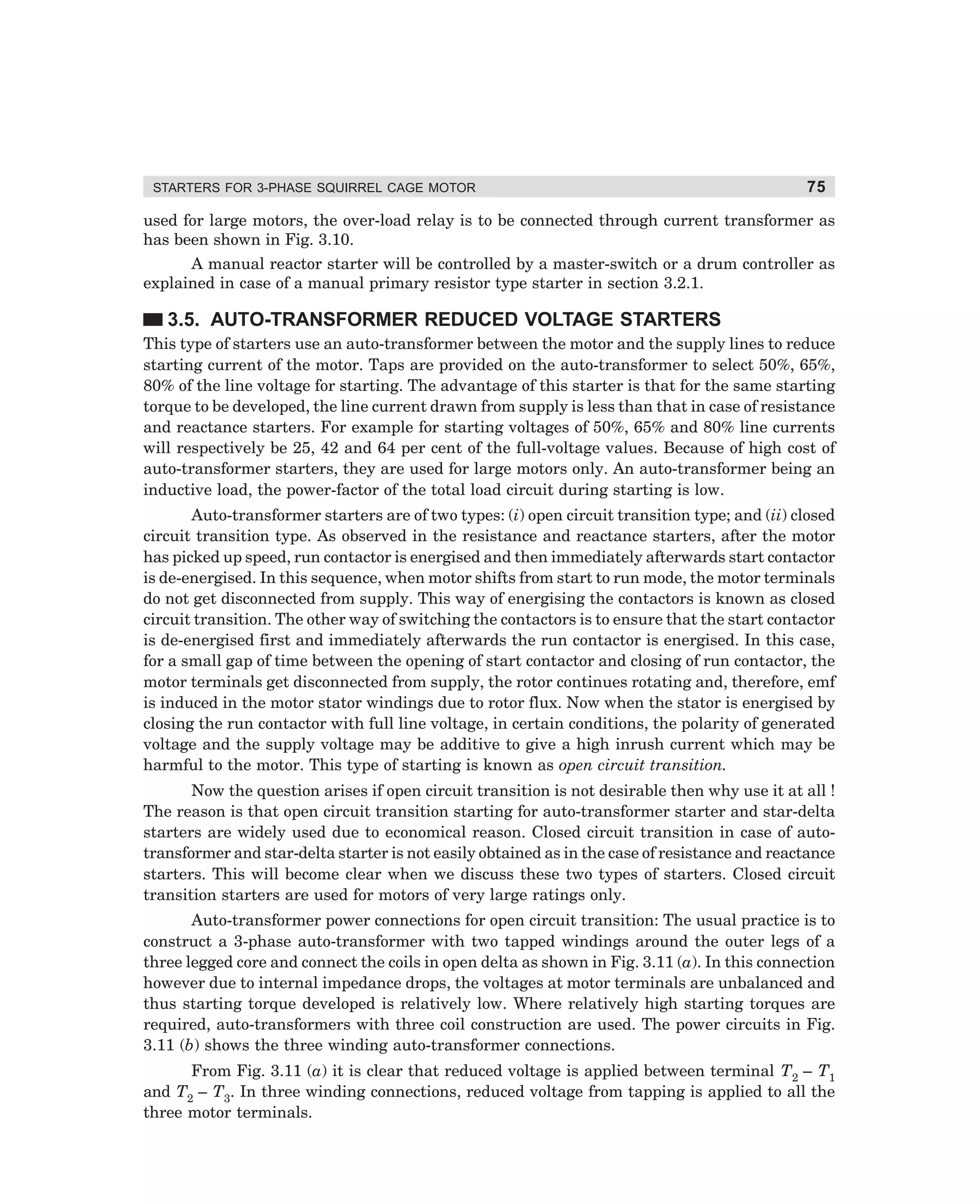
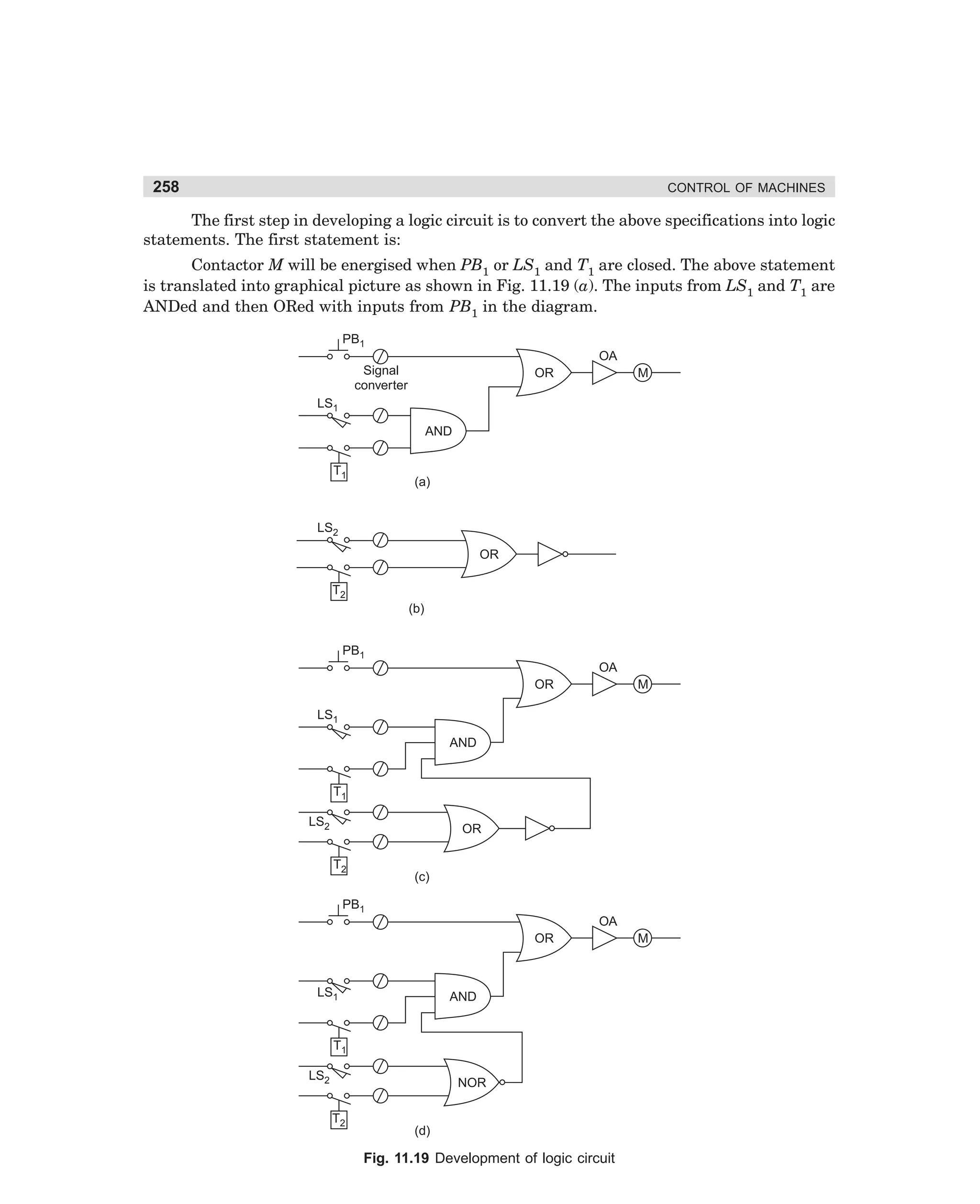
CR2
P
TR1
R1
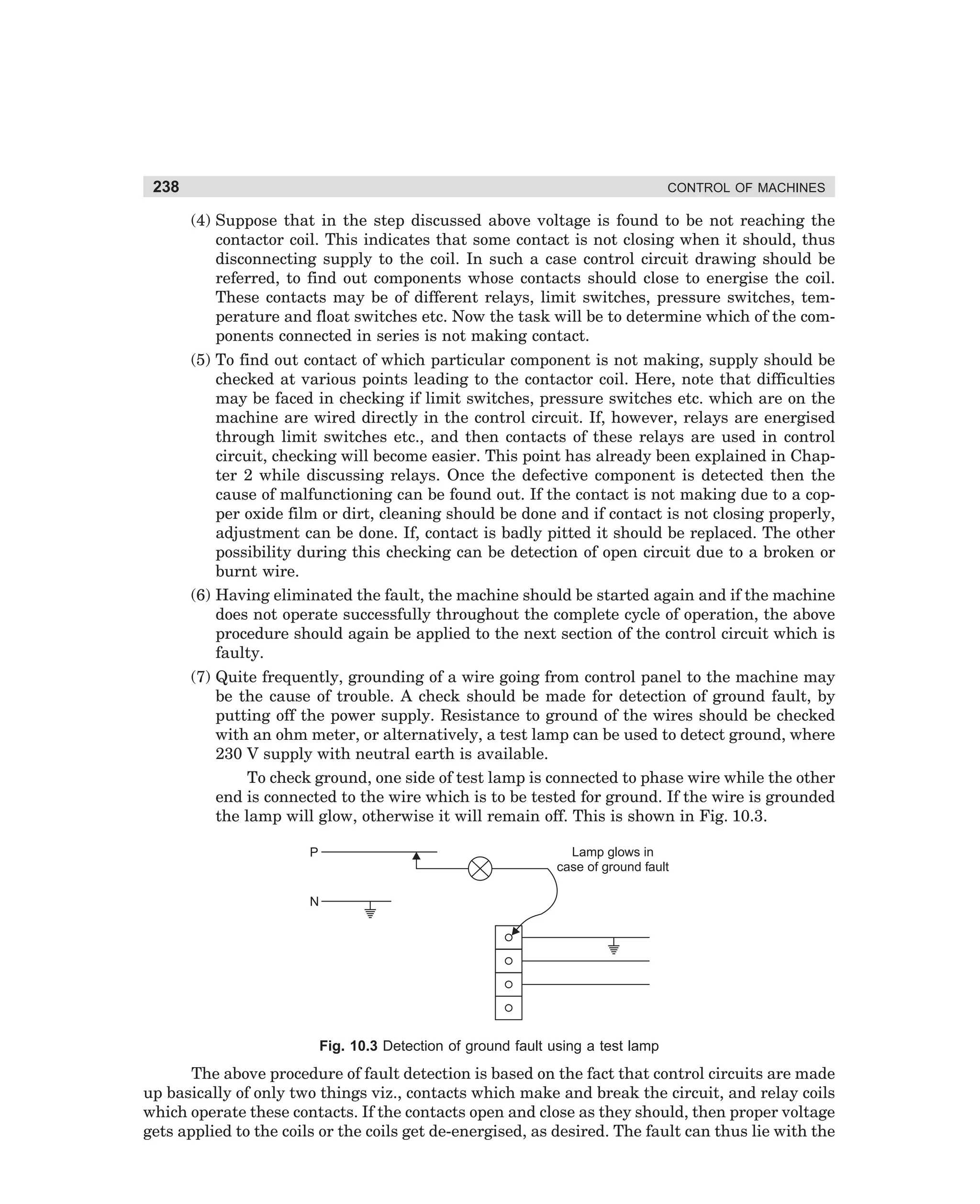
R2
OFF
CR1
ON
CR
S
TR
R
N
(b)
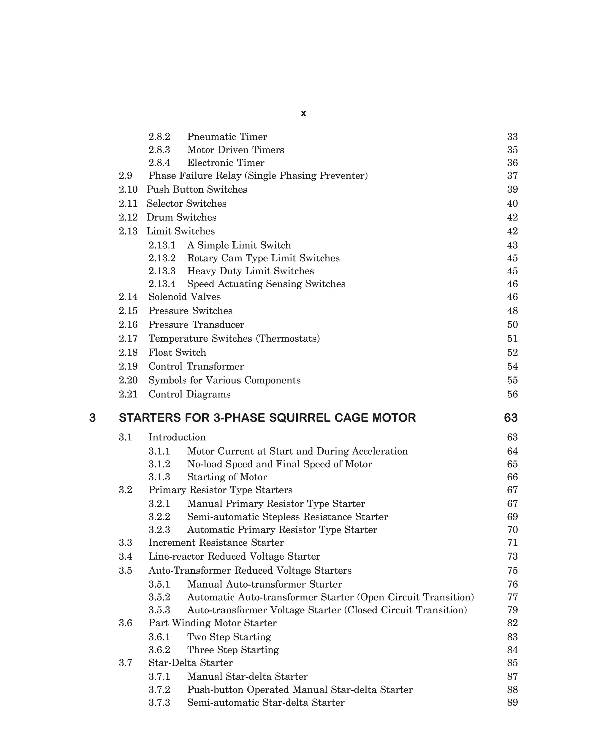
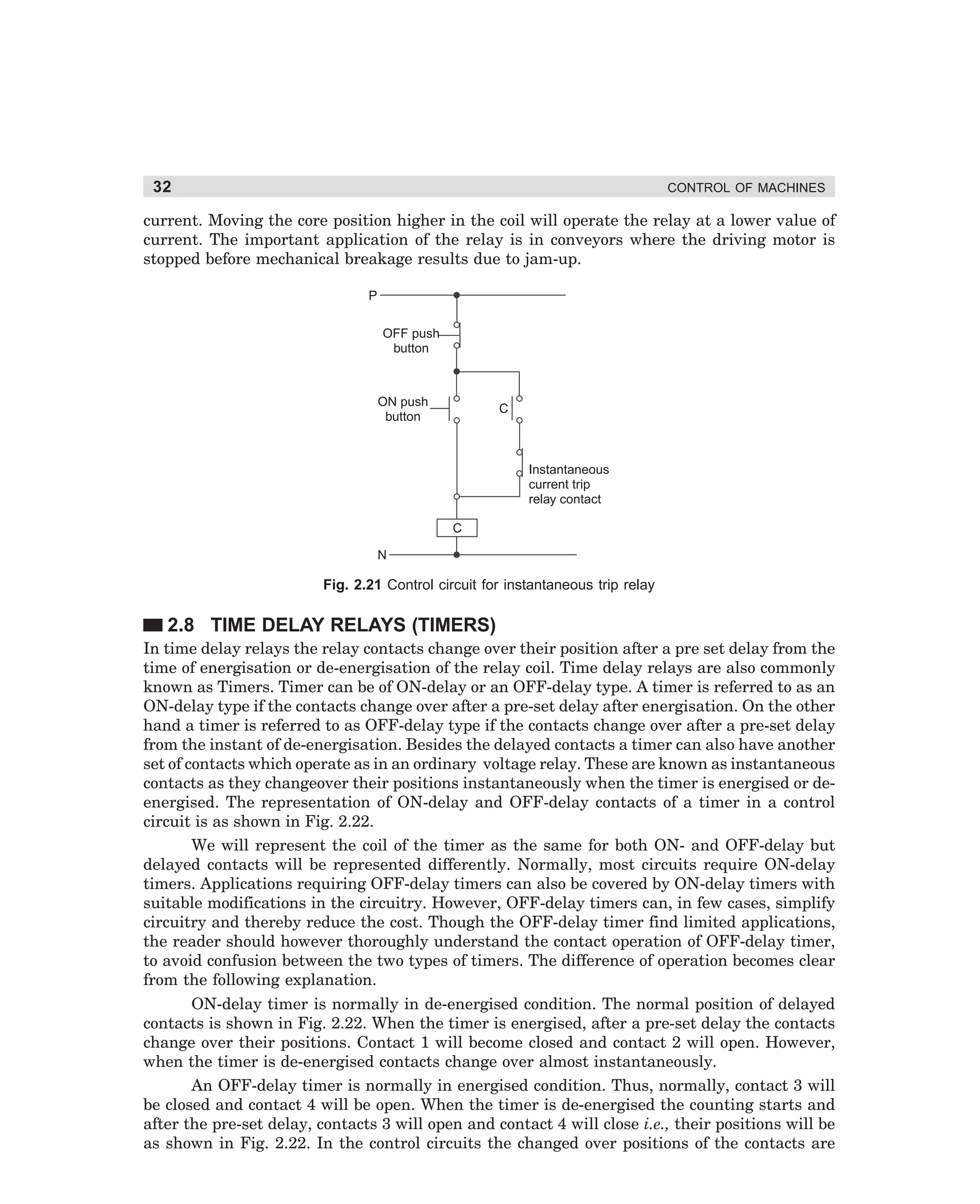
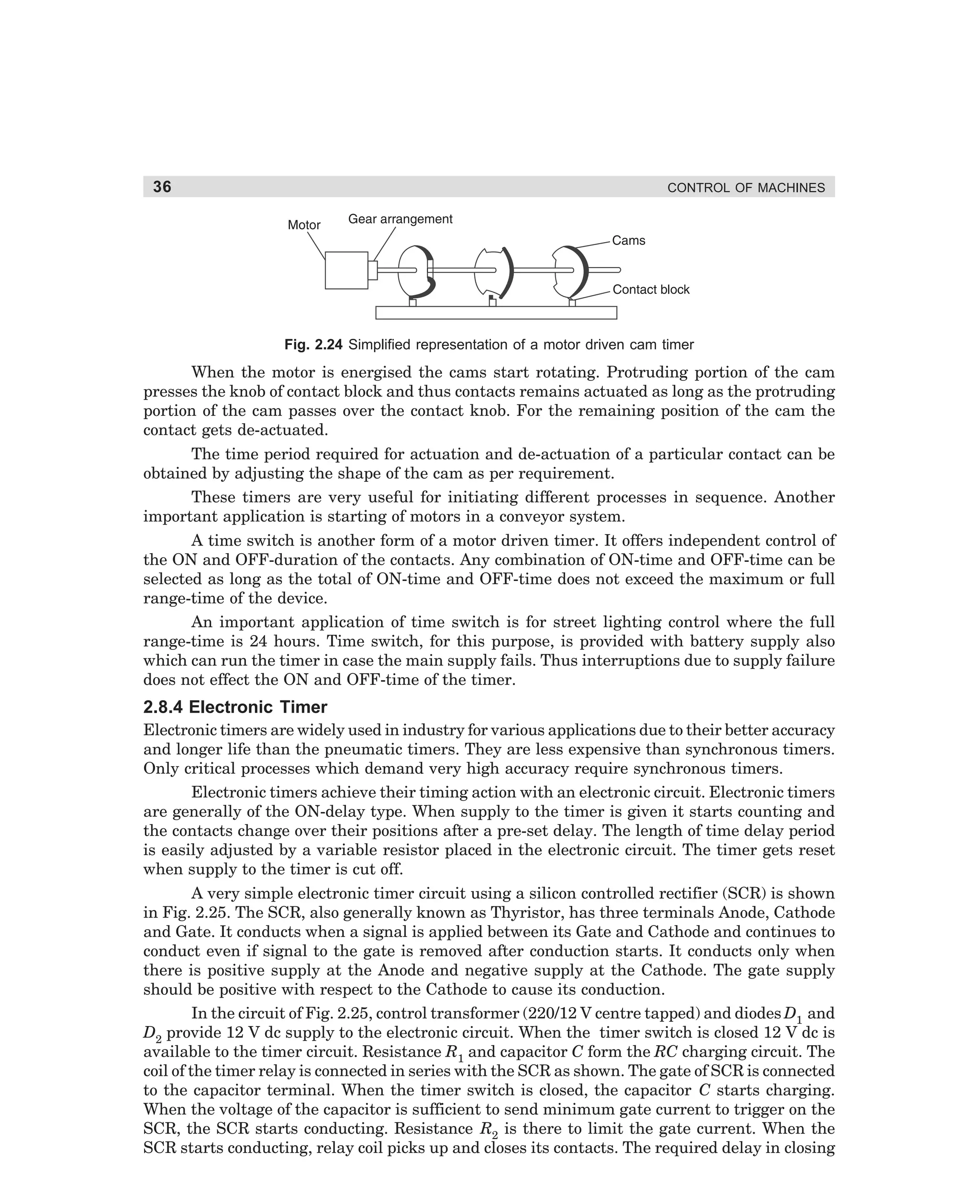
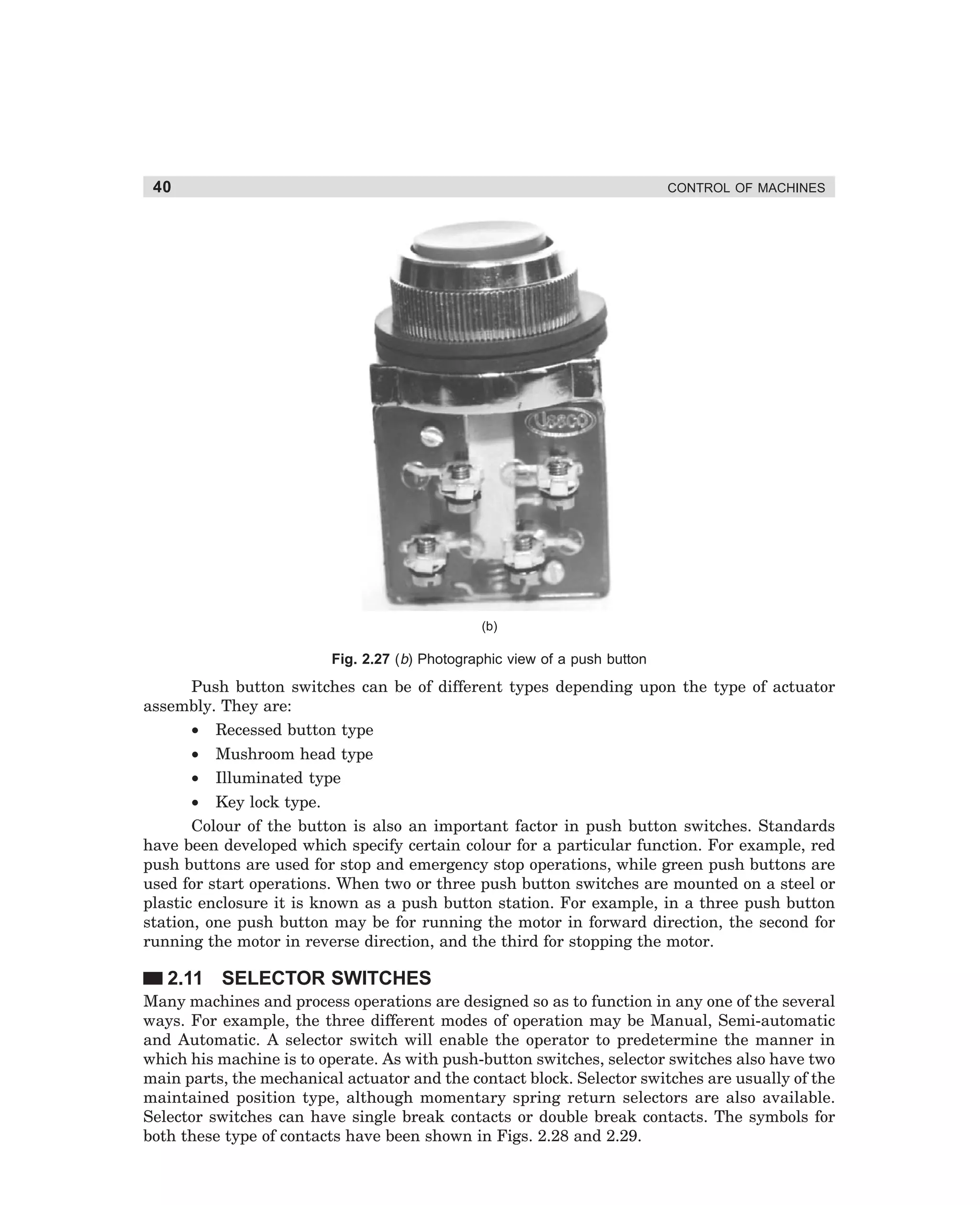
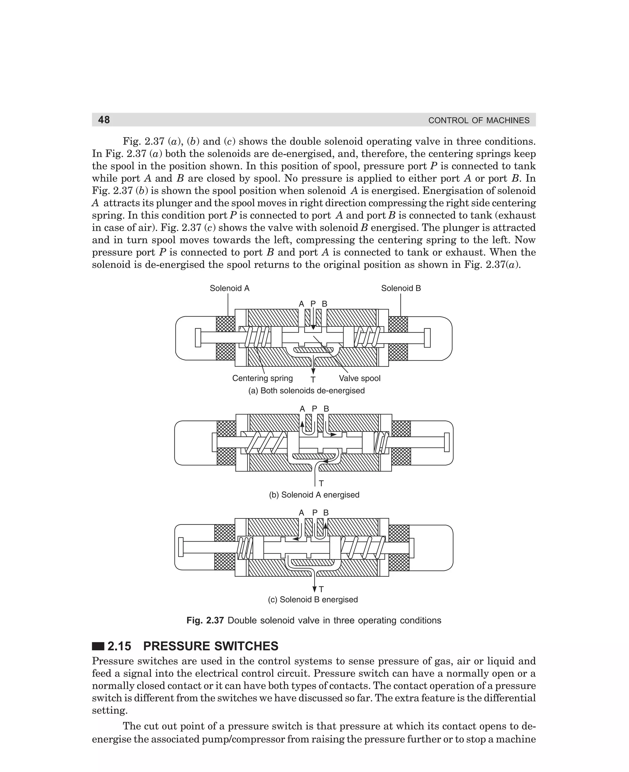
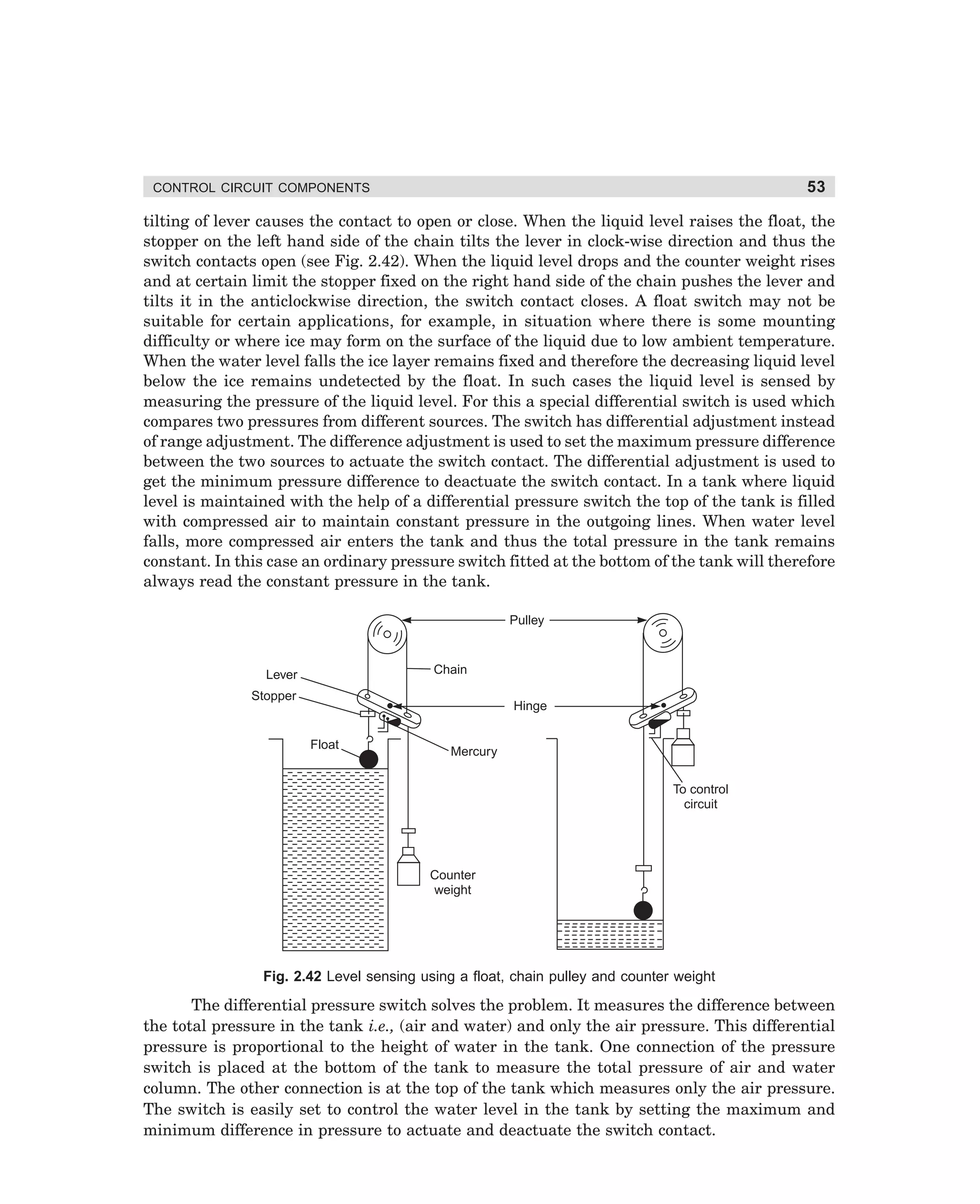
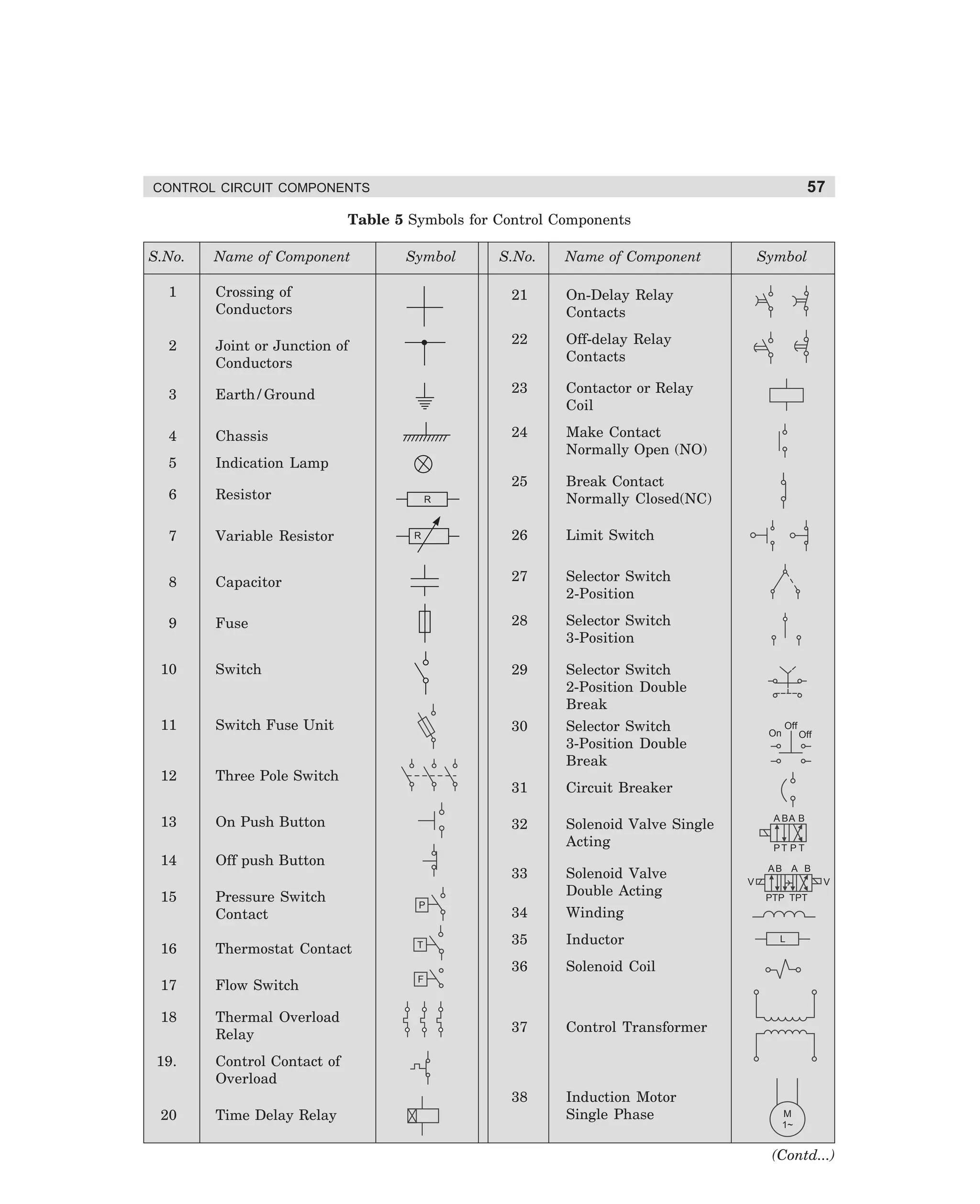
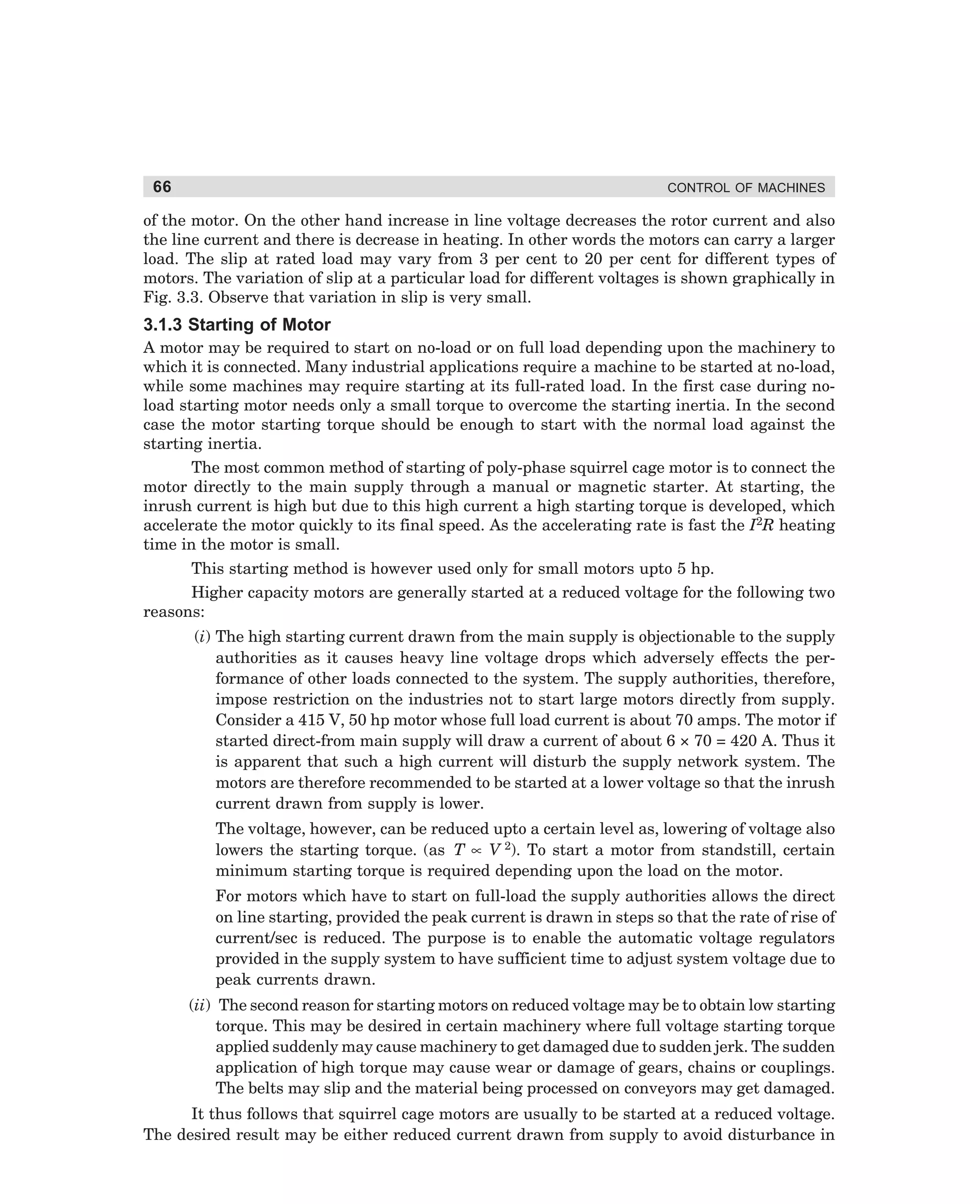
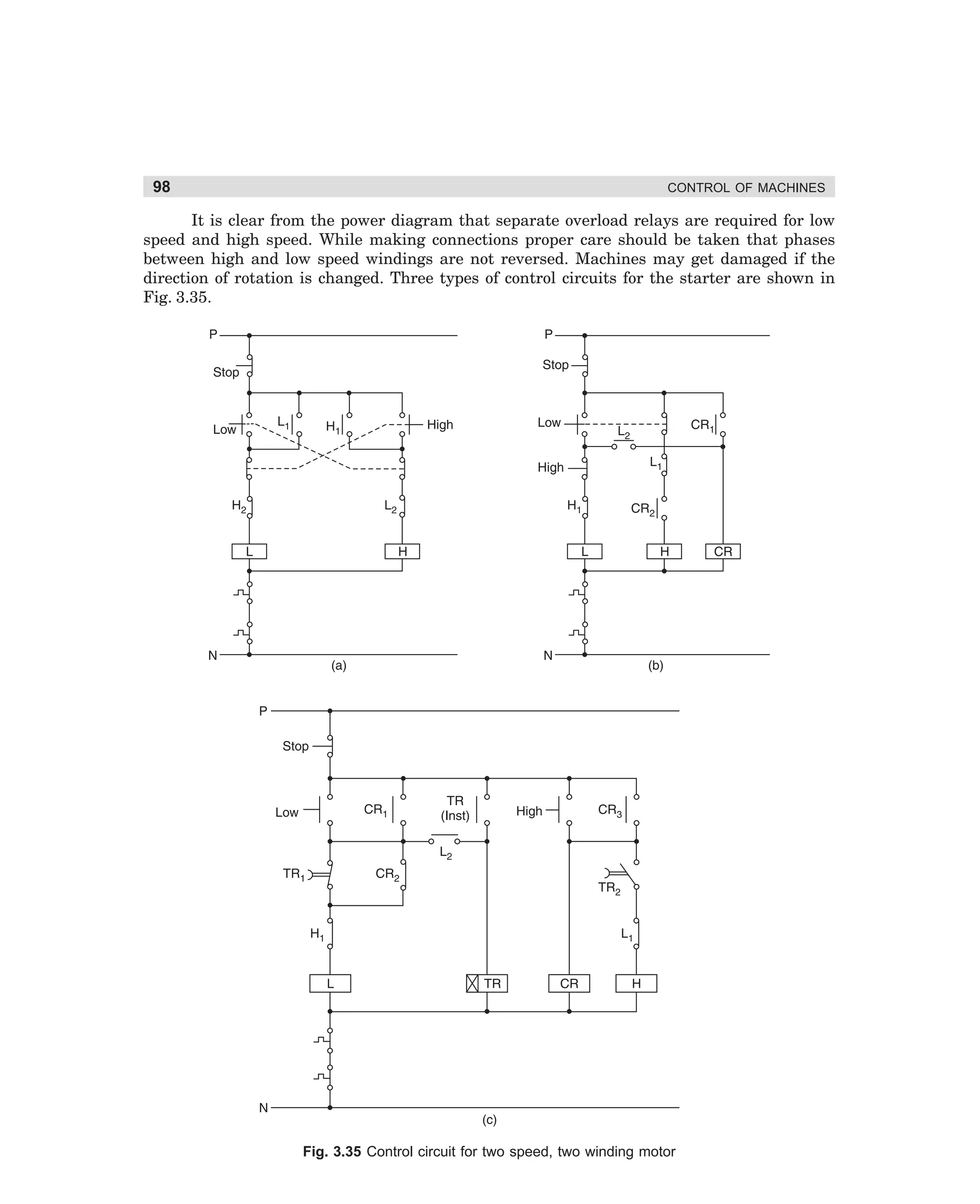
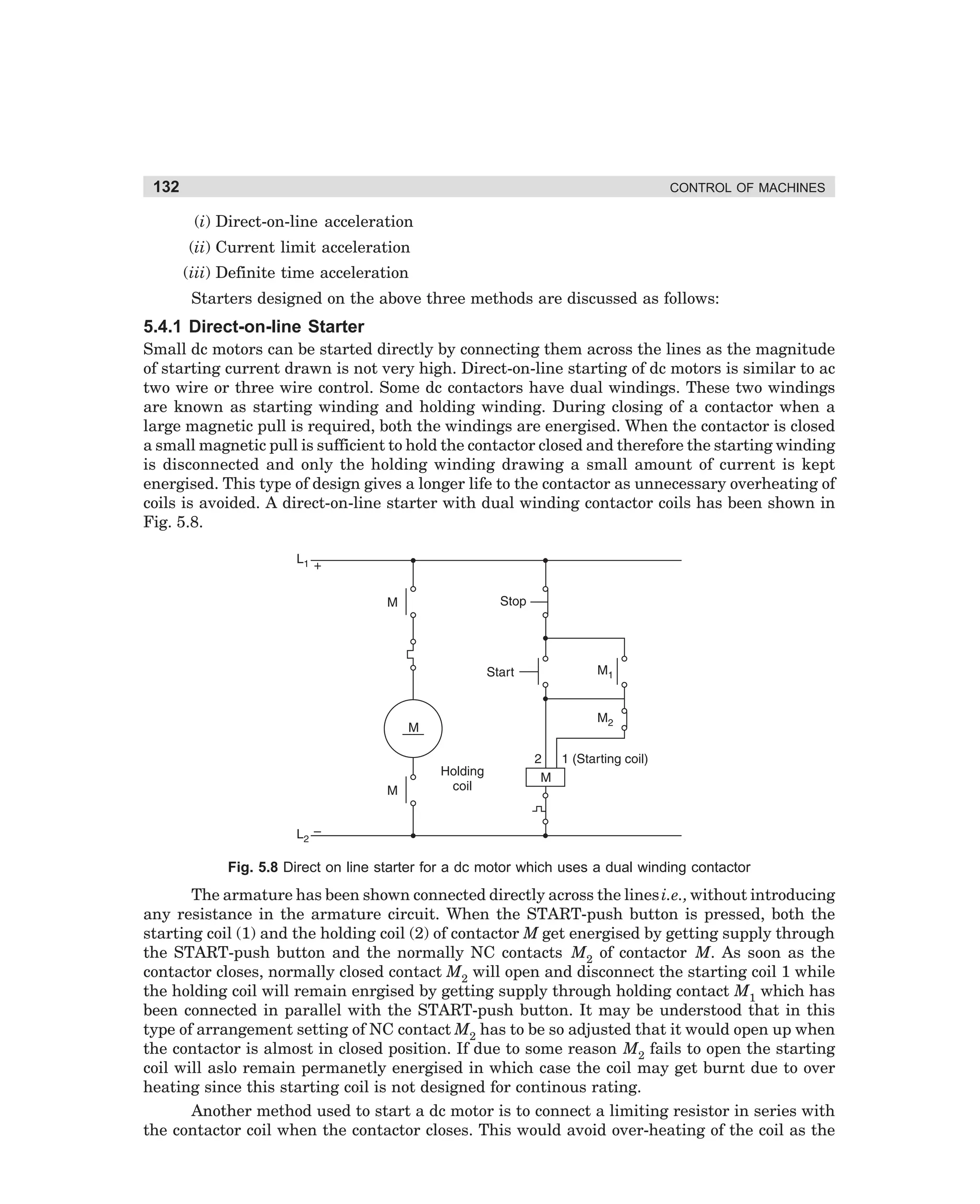
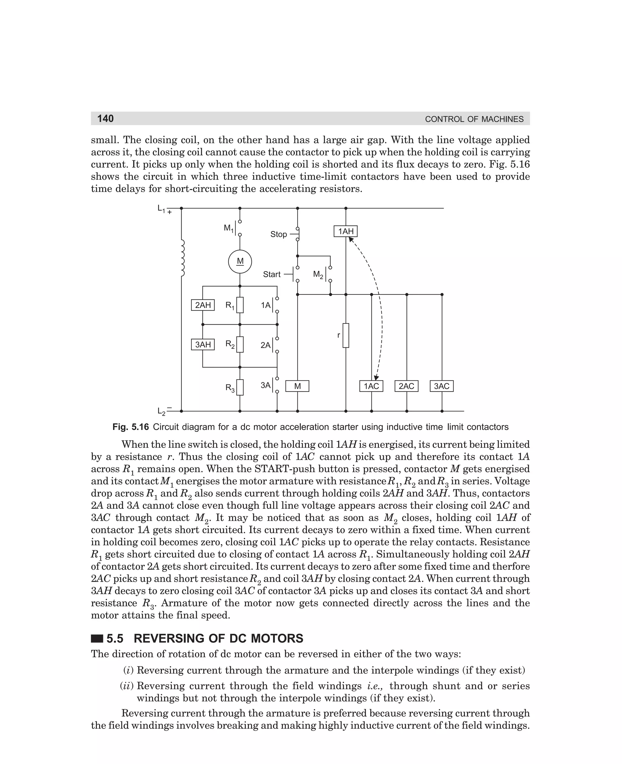
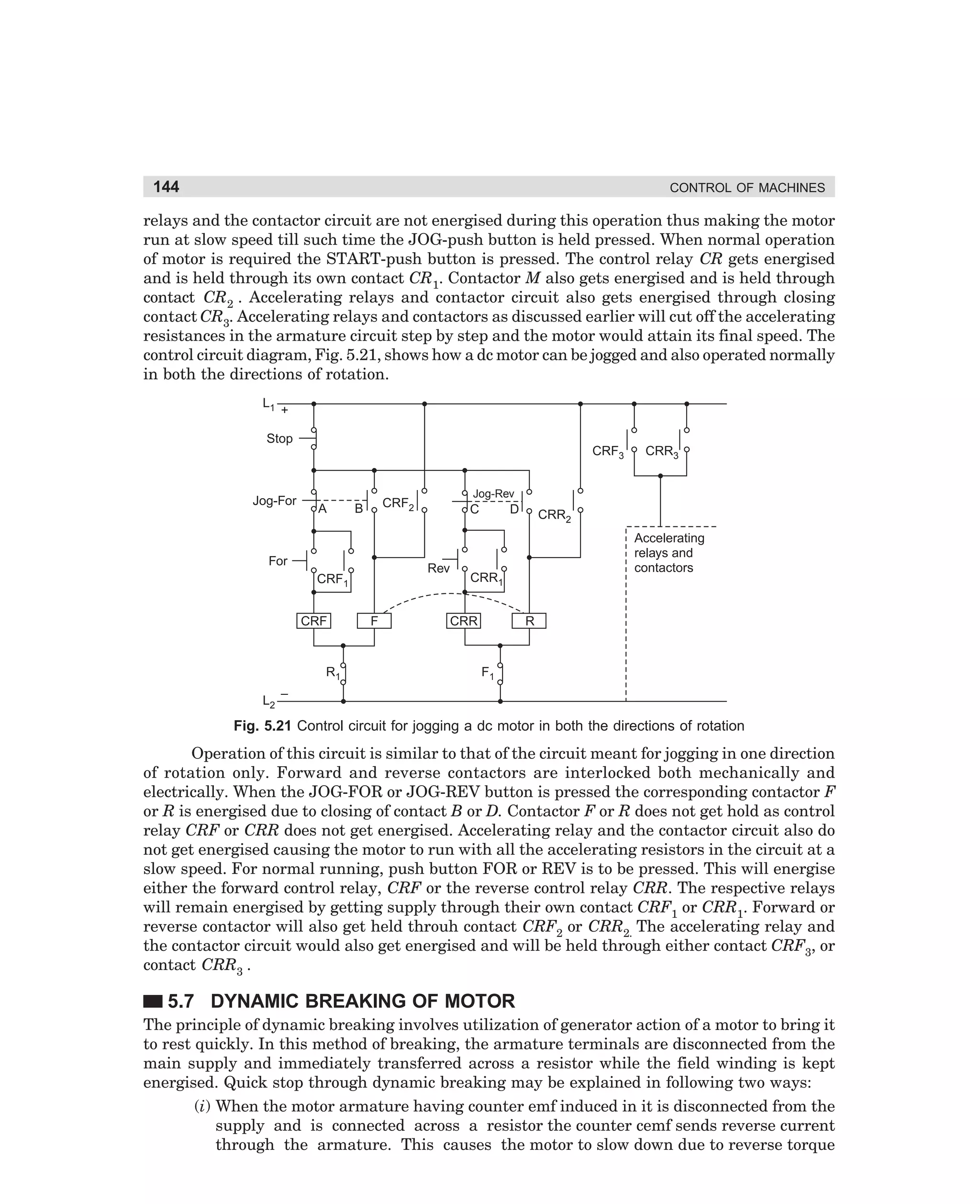
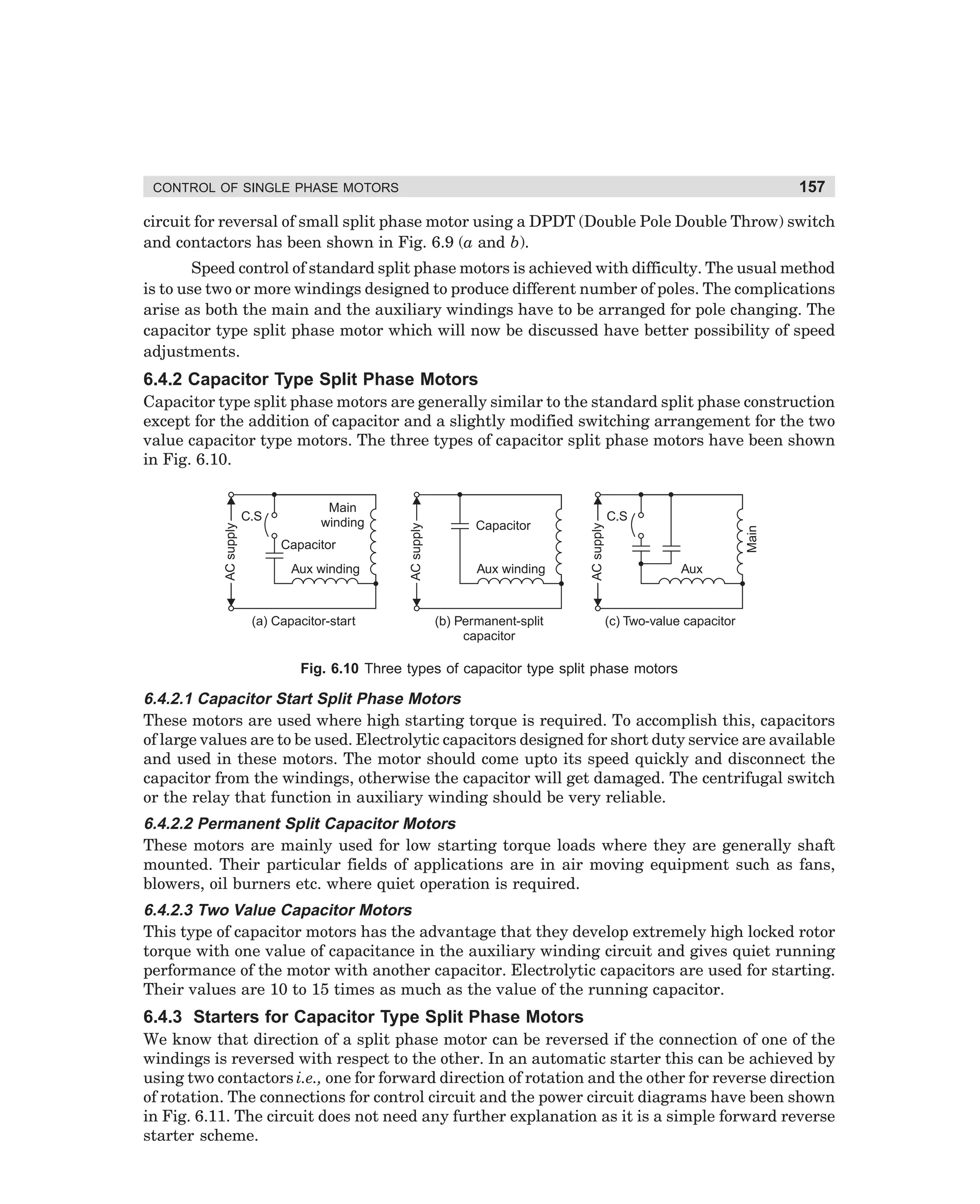
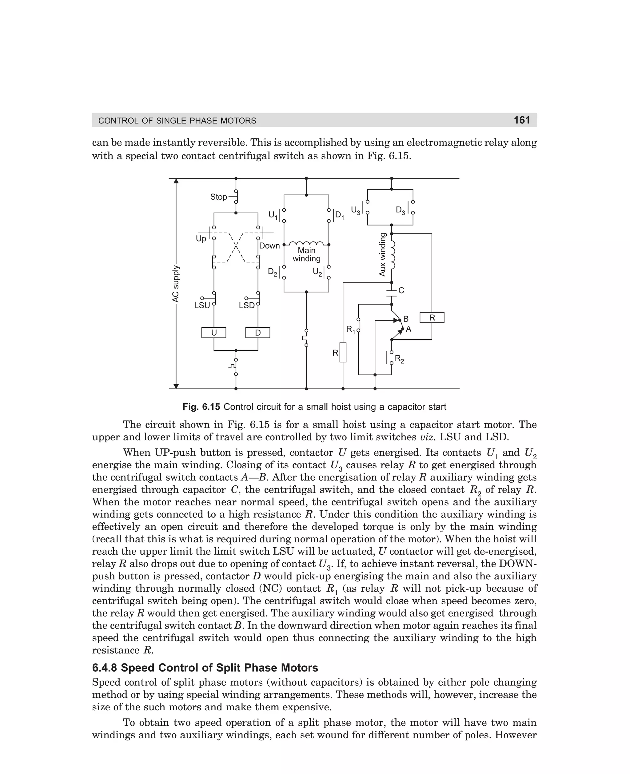
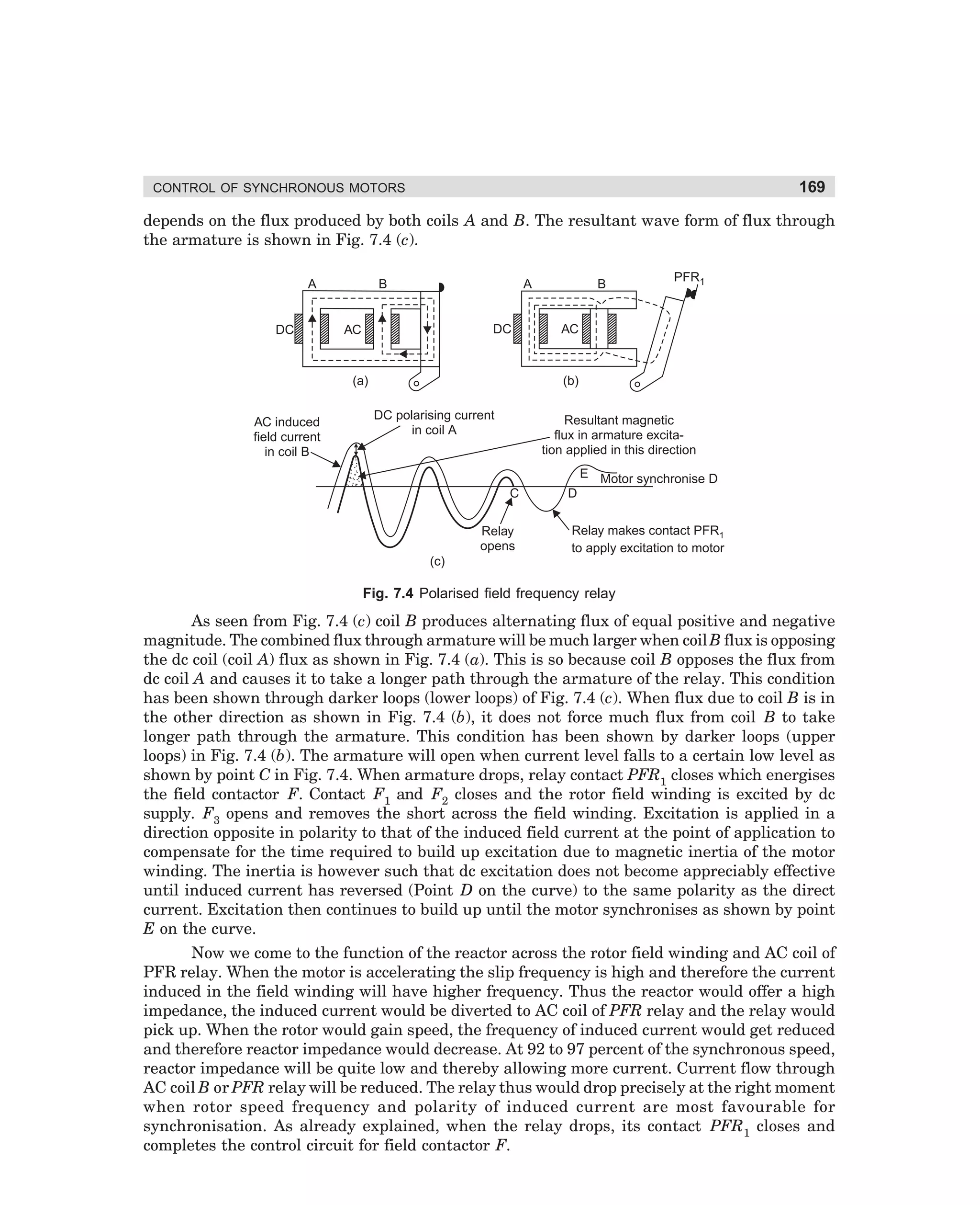
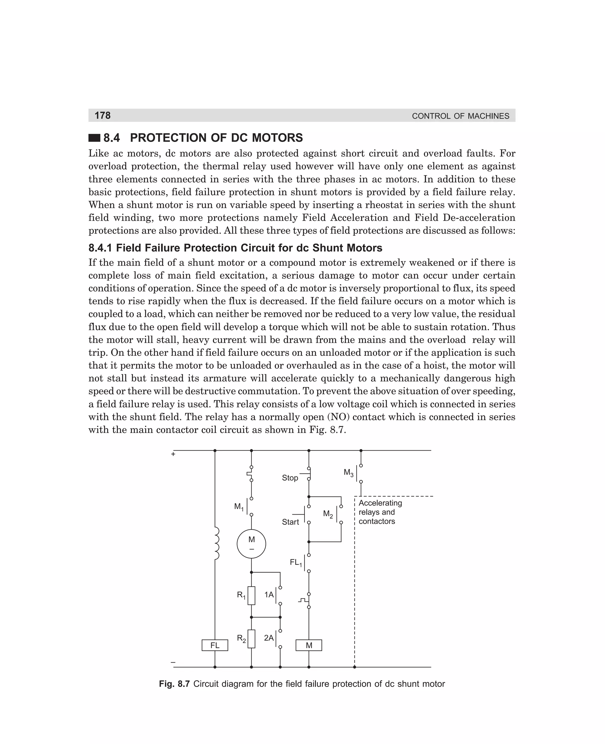
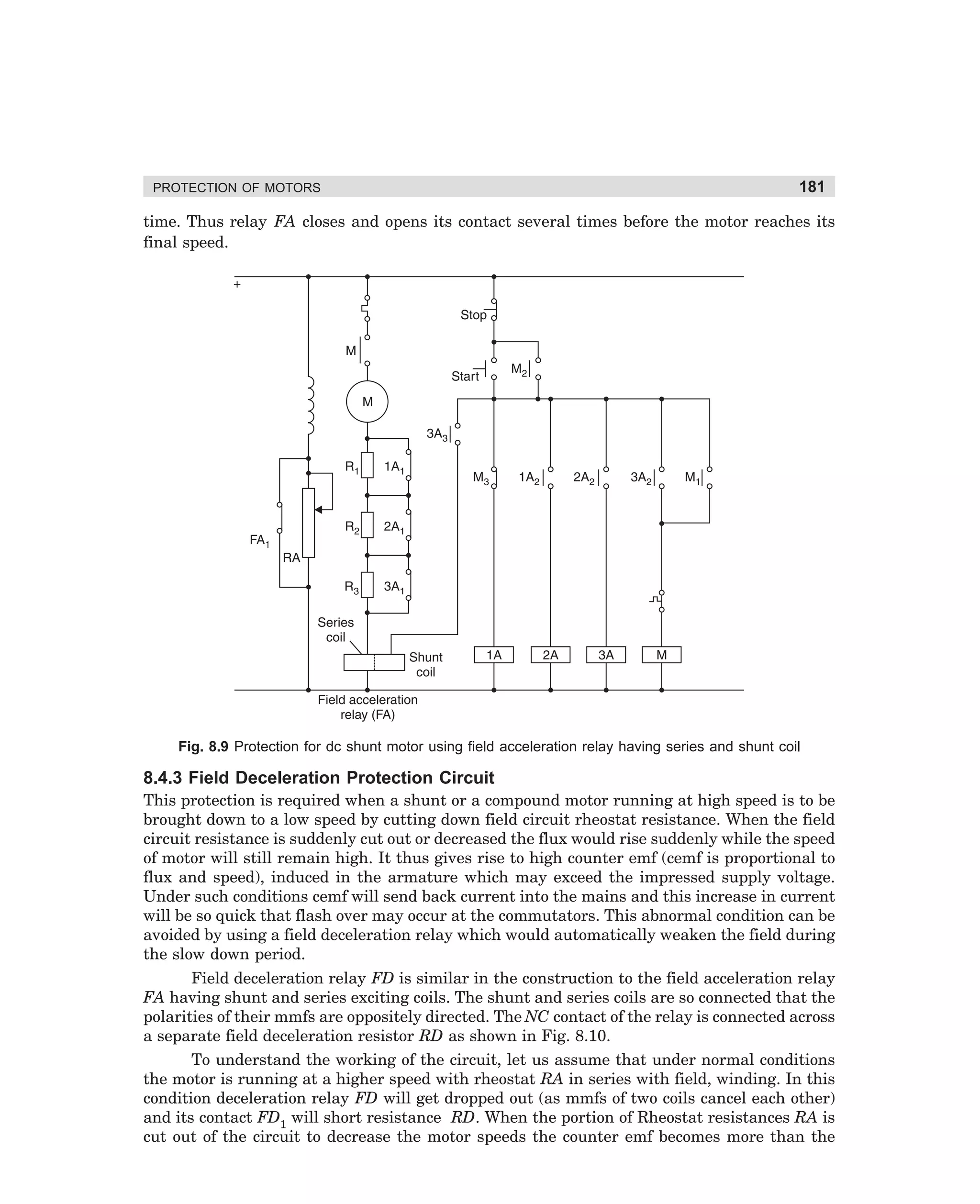
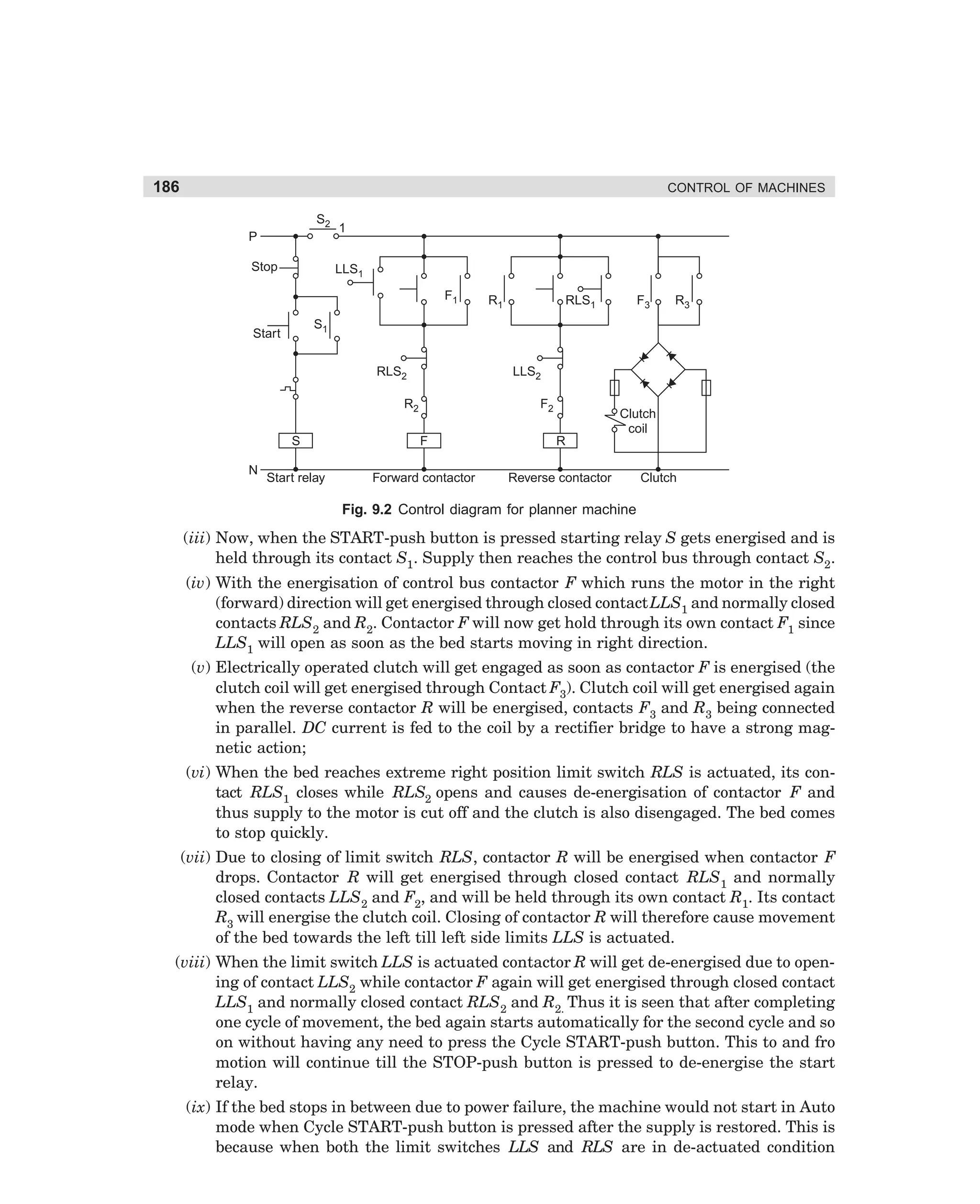
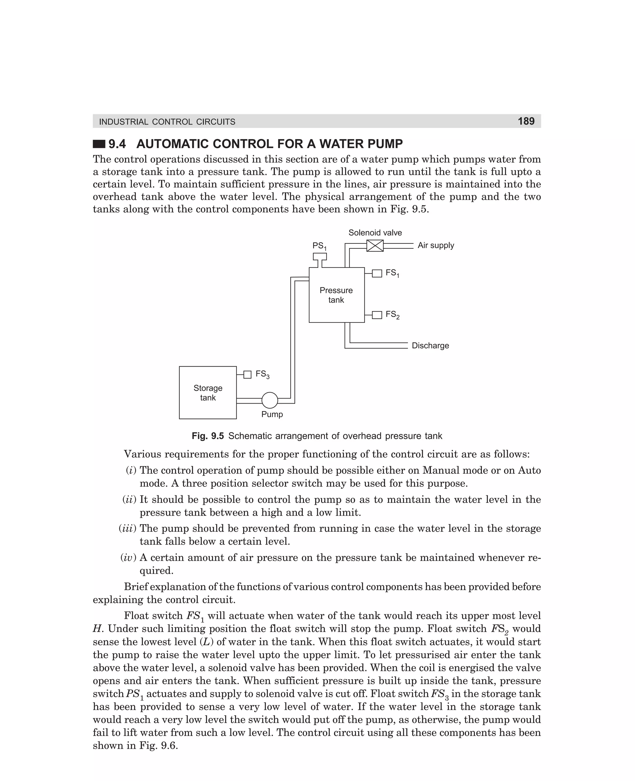
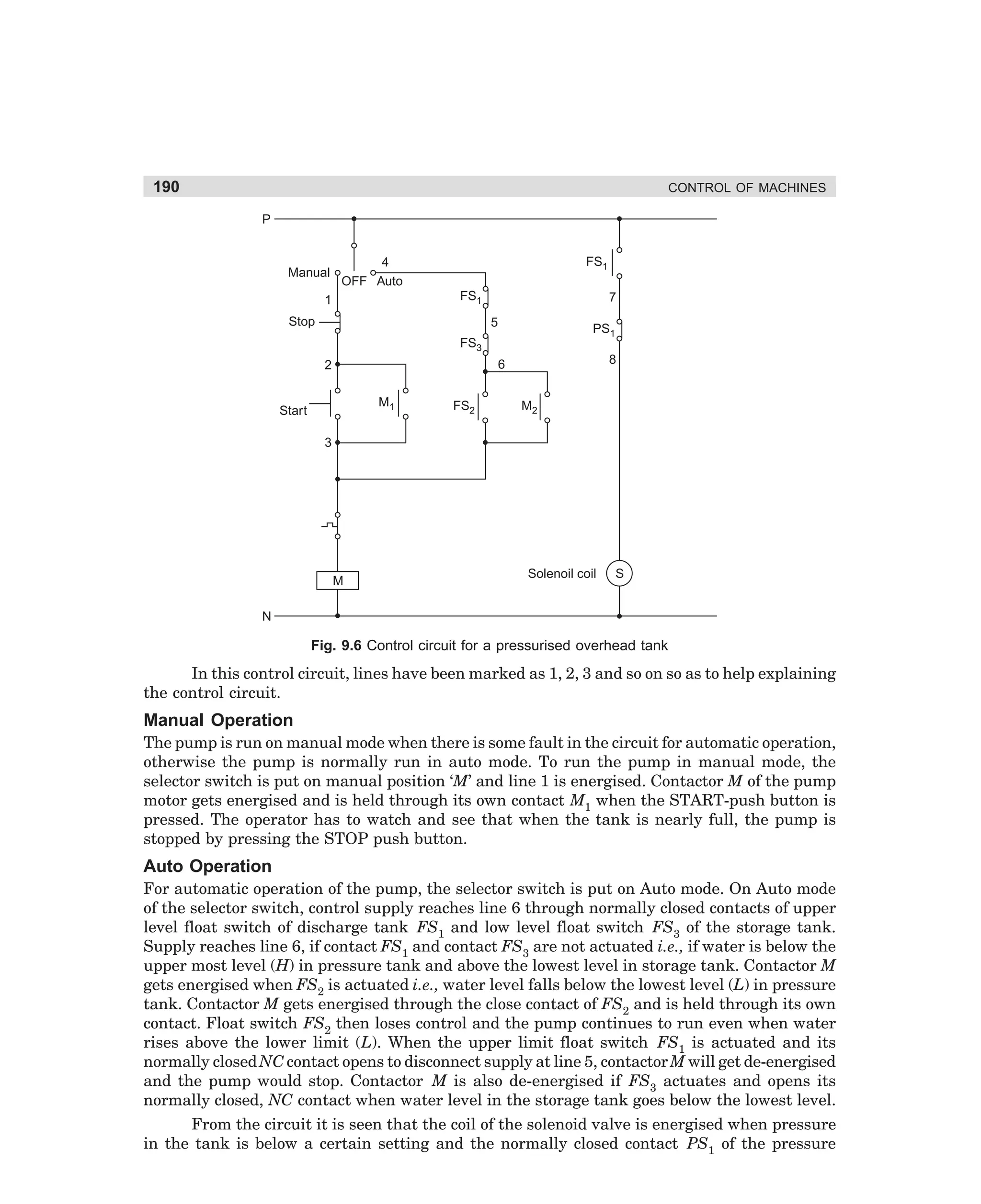
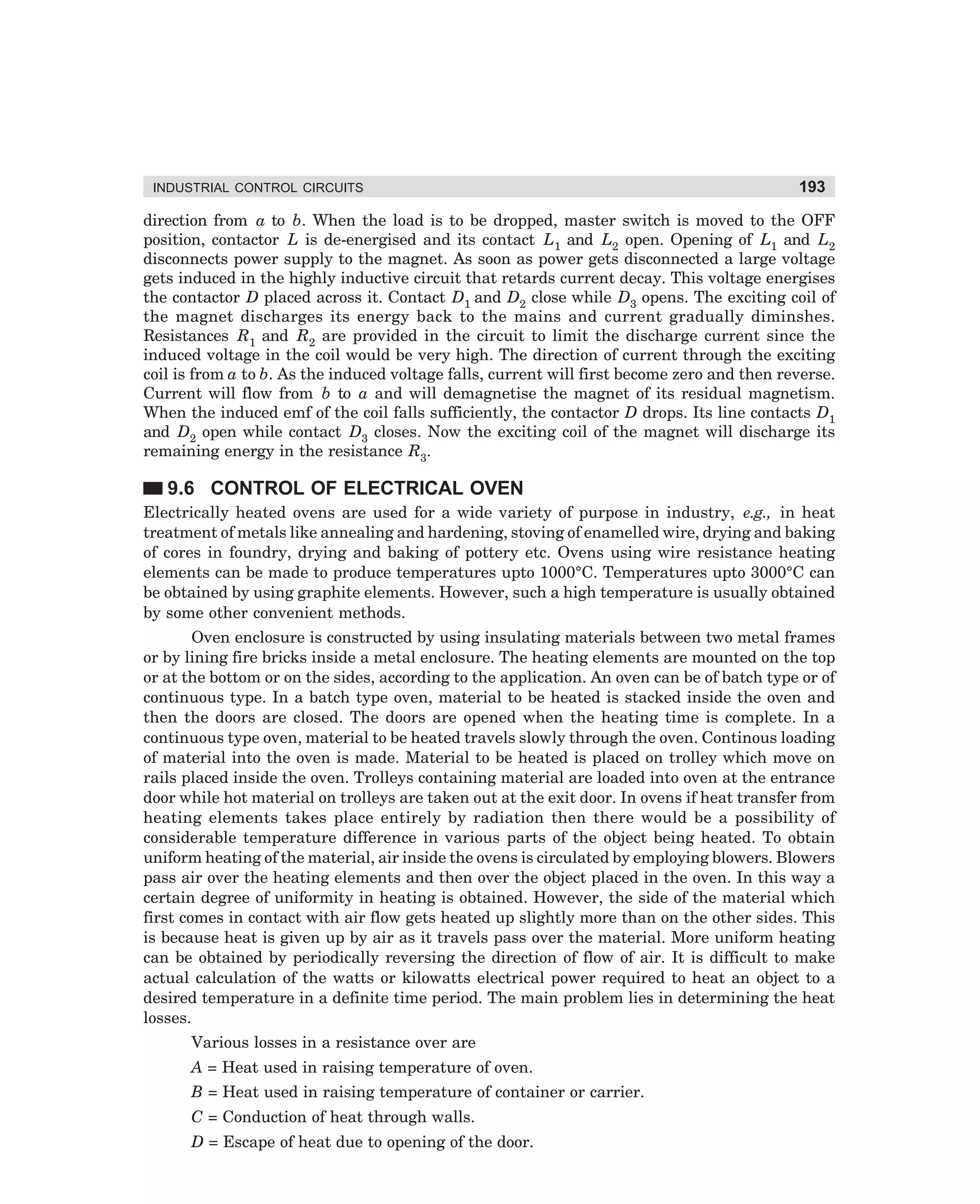
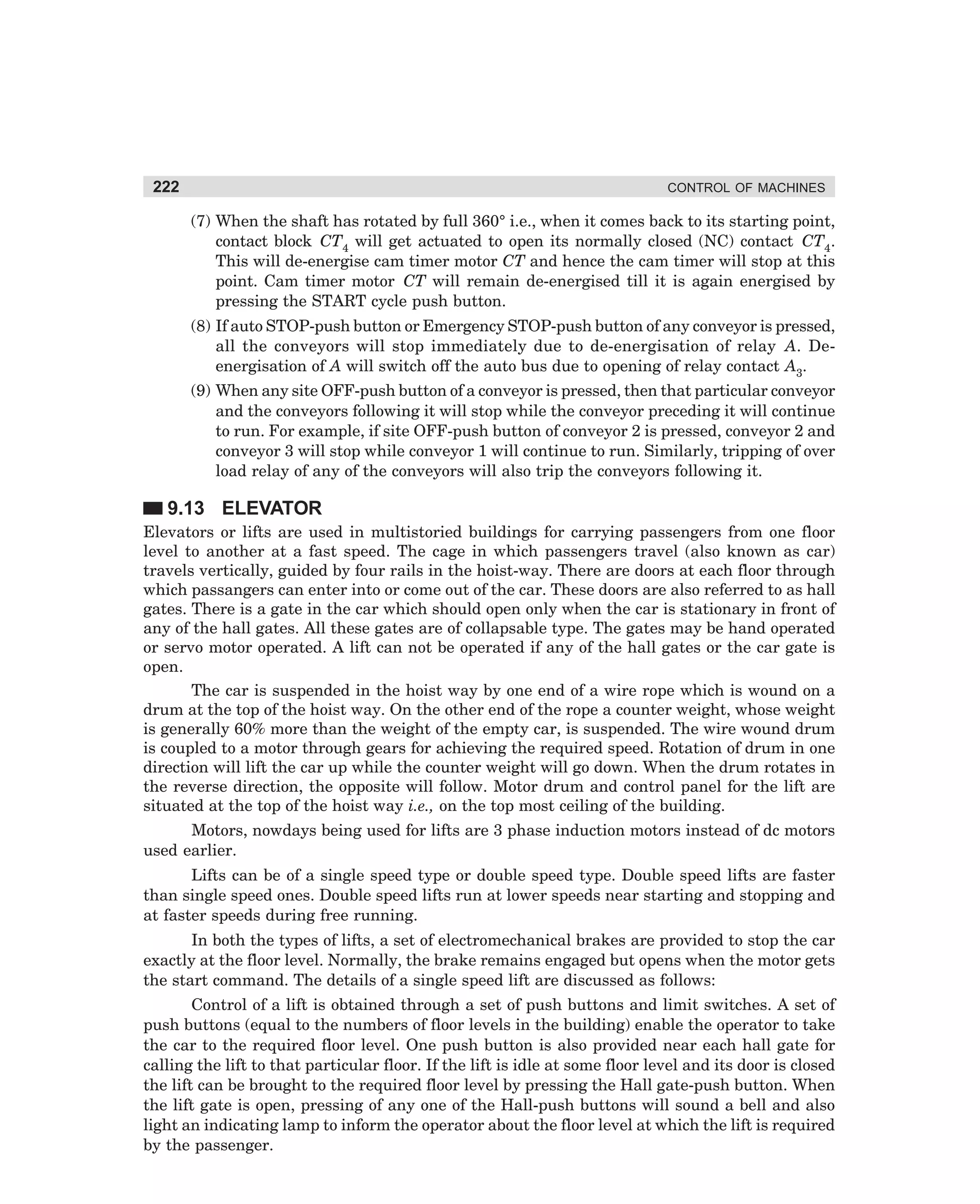
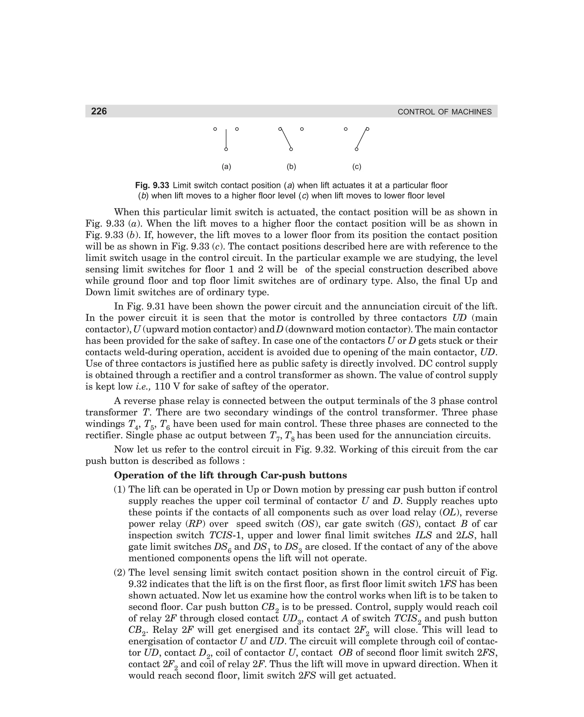
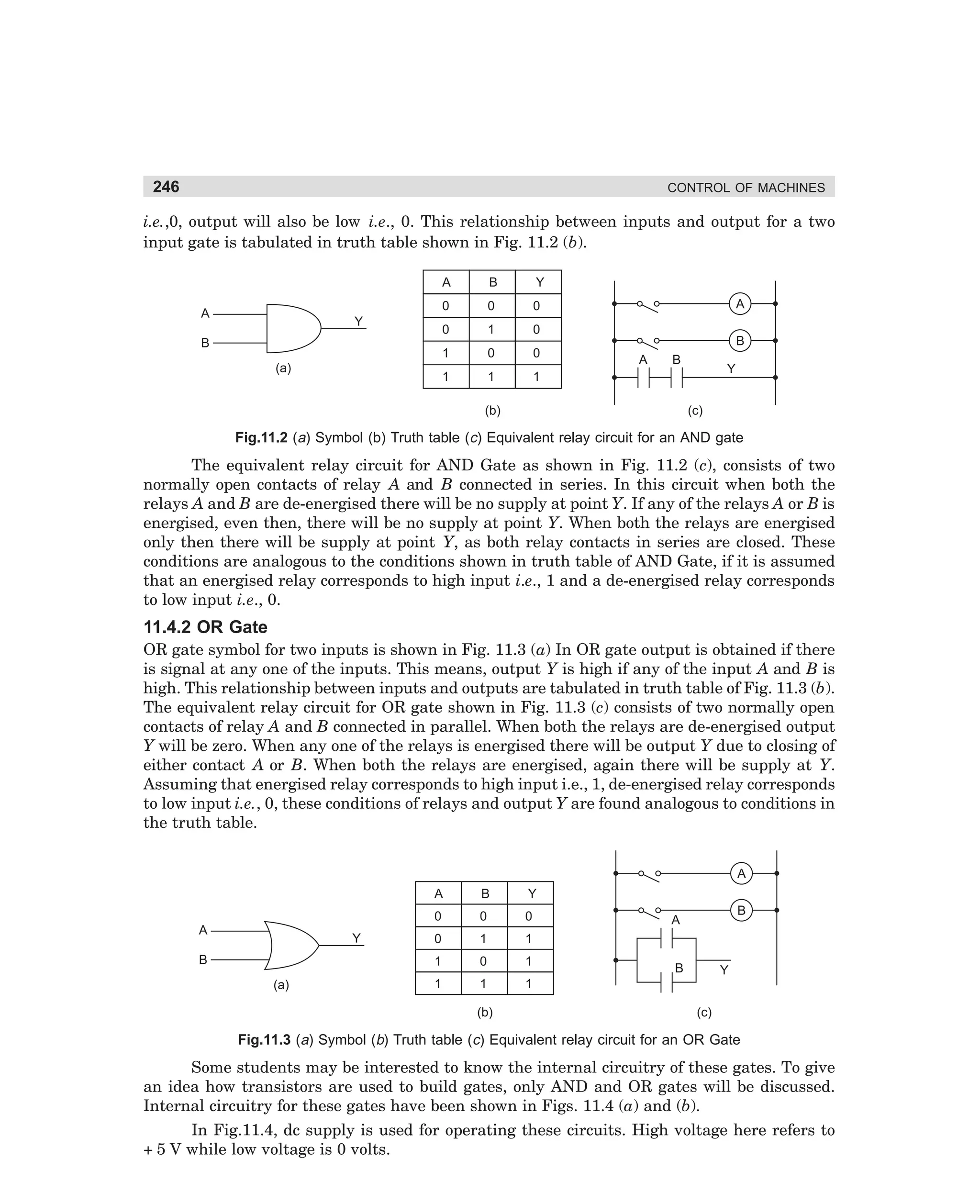
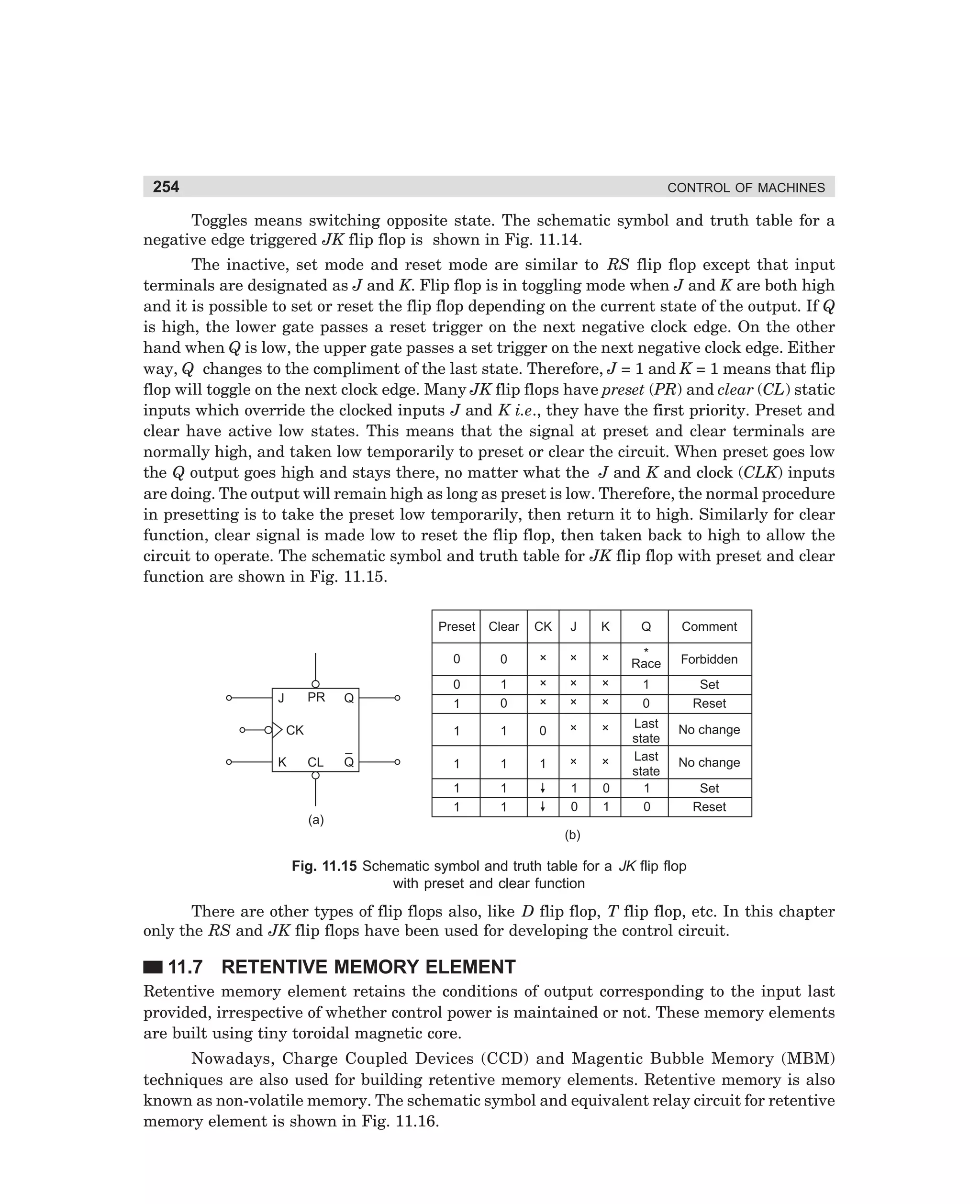
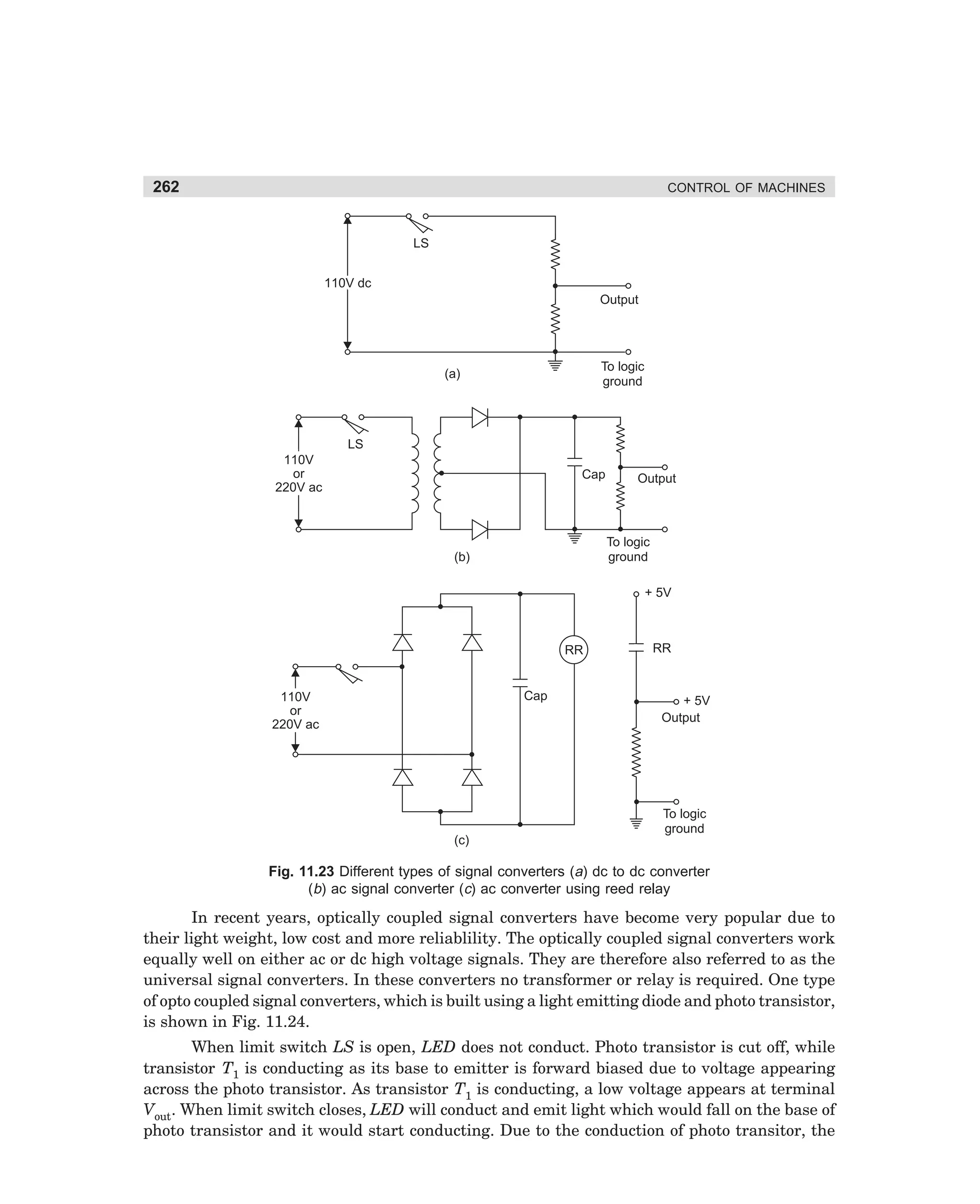
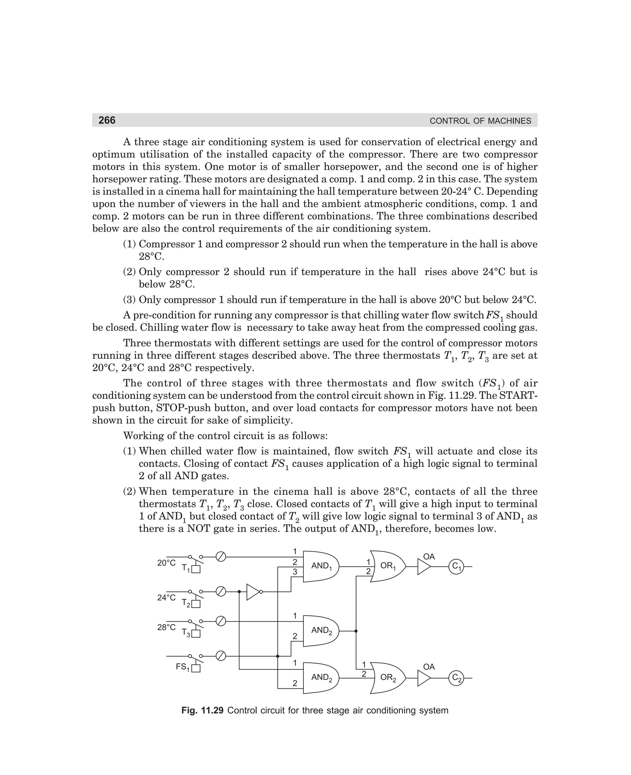
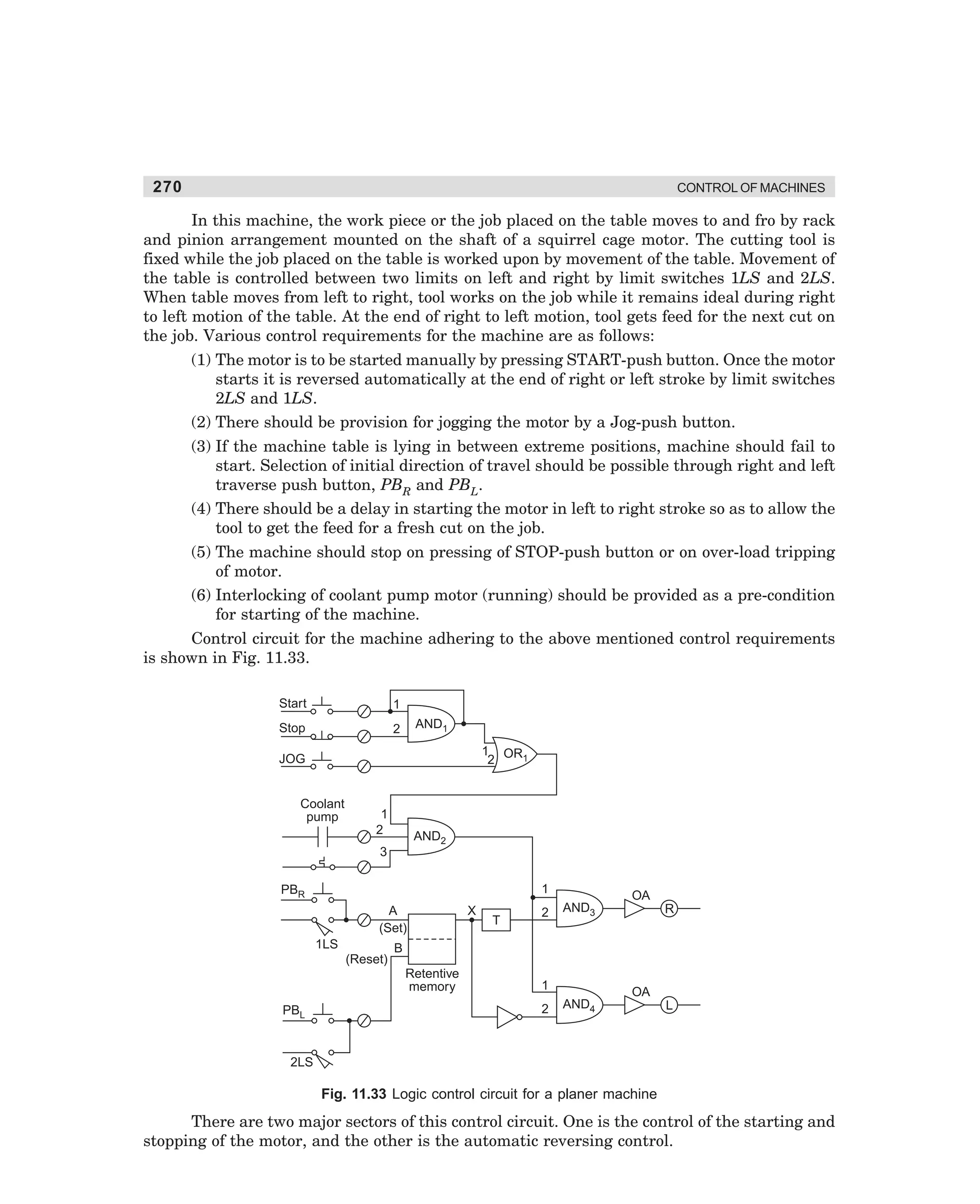
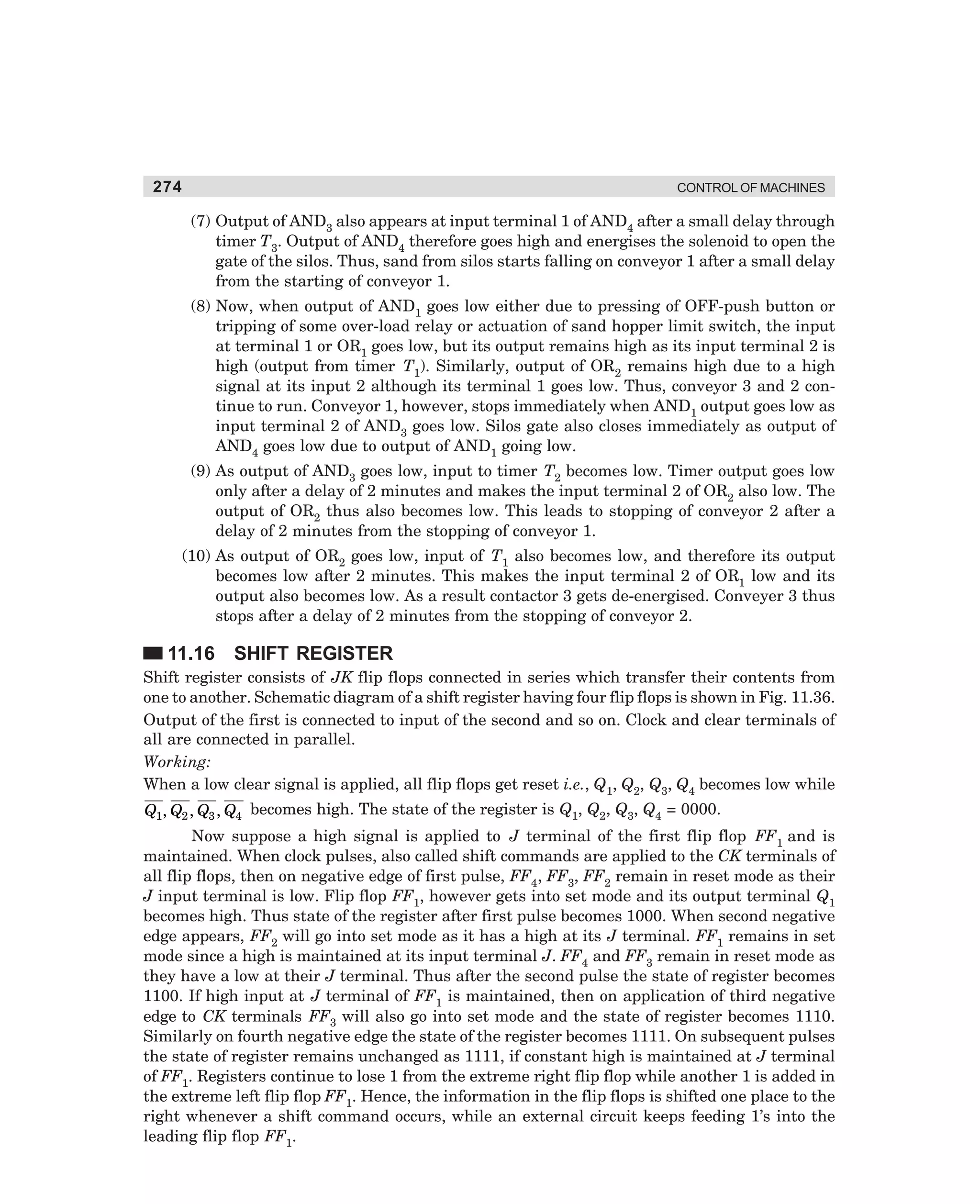
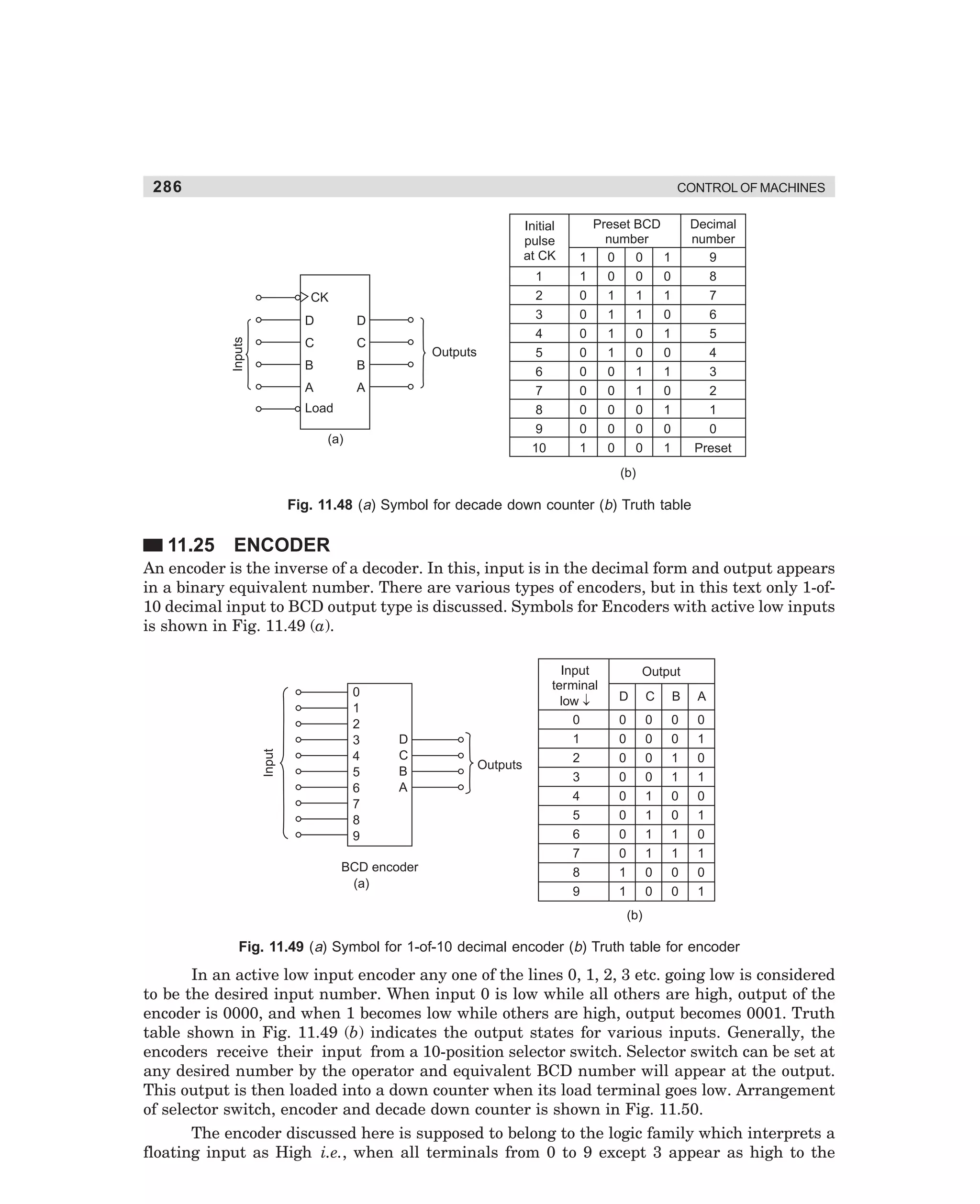
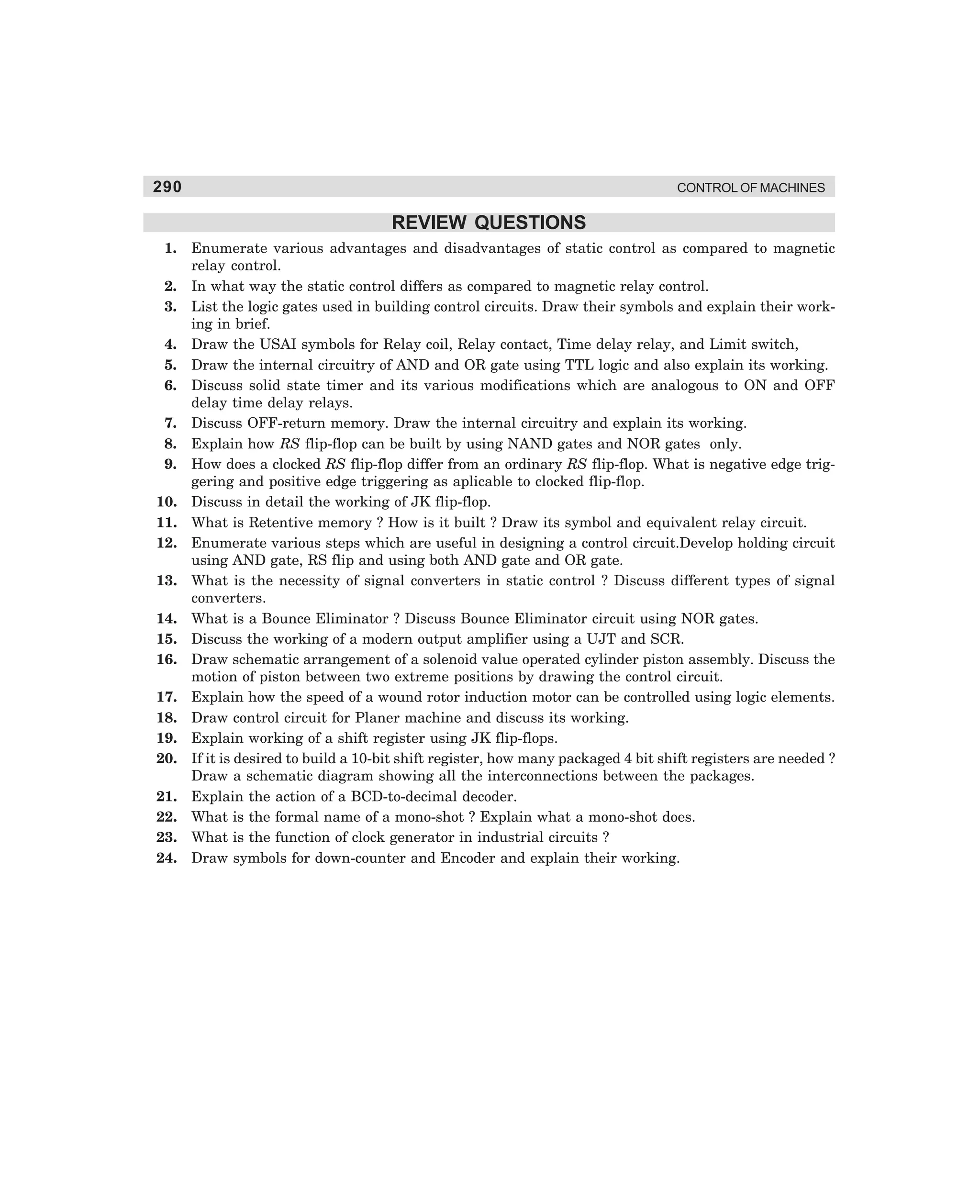
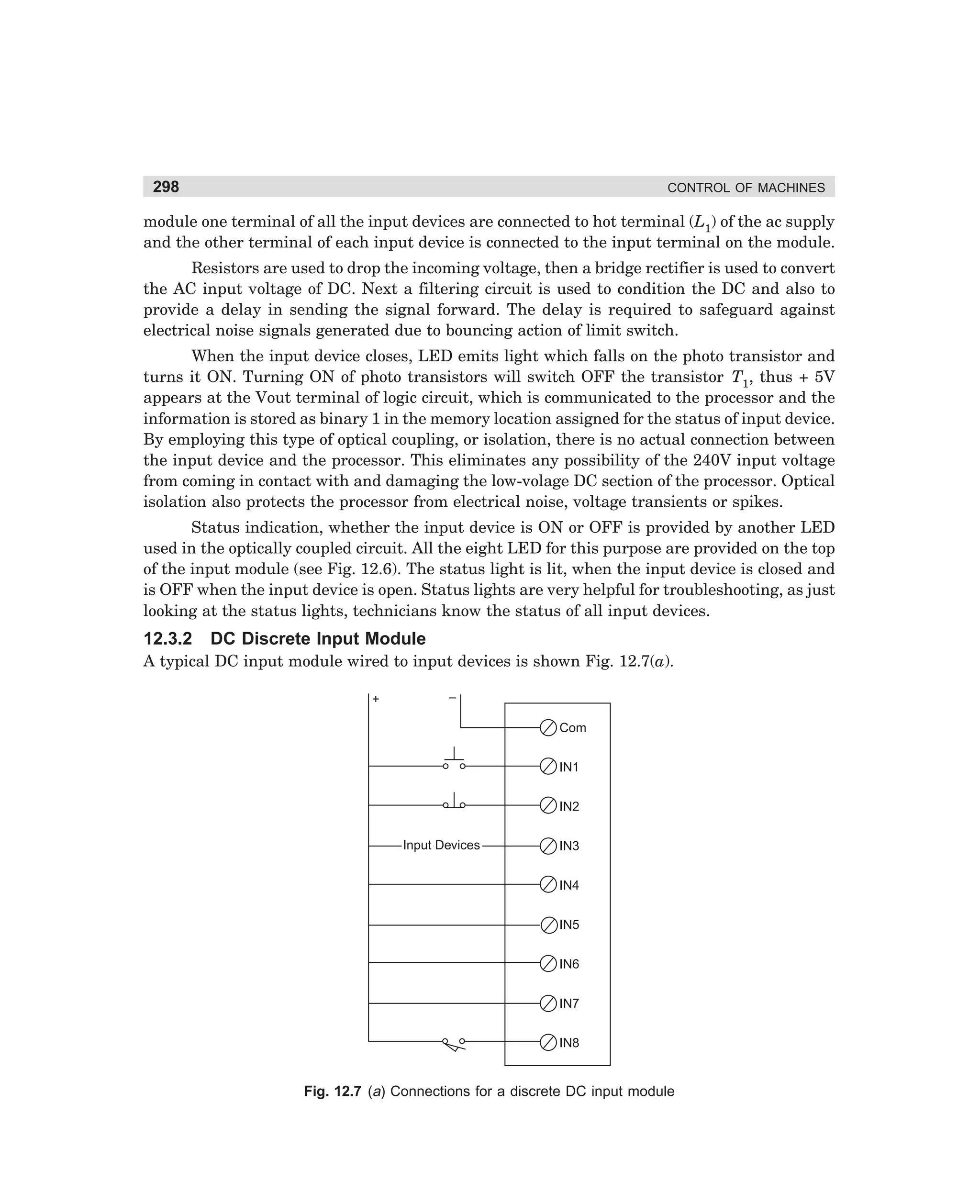
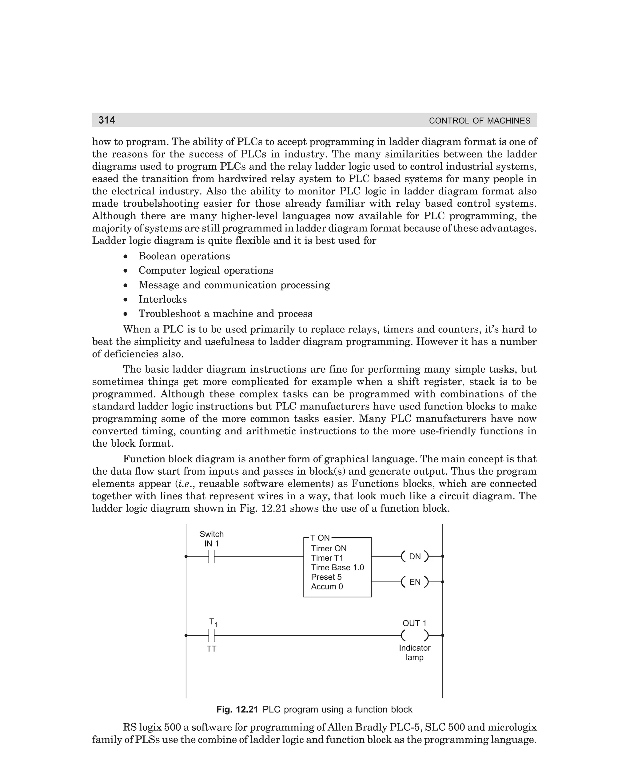
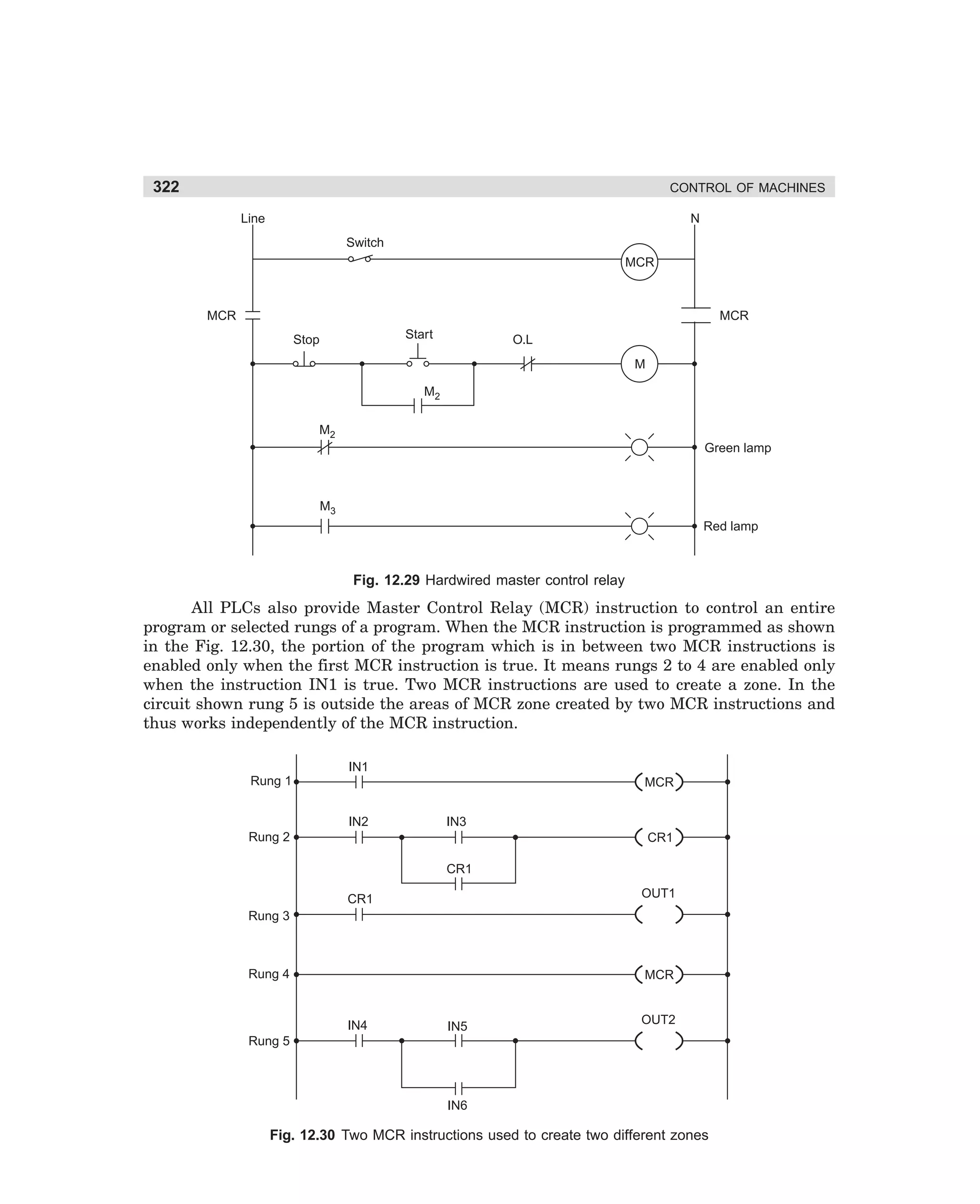
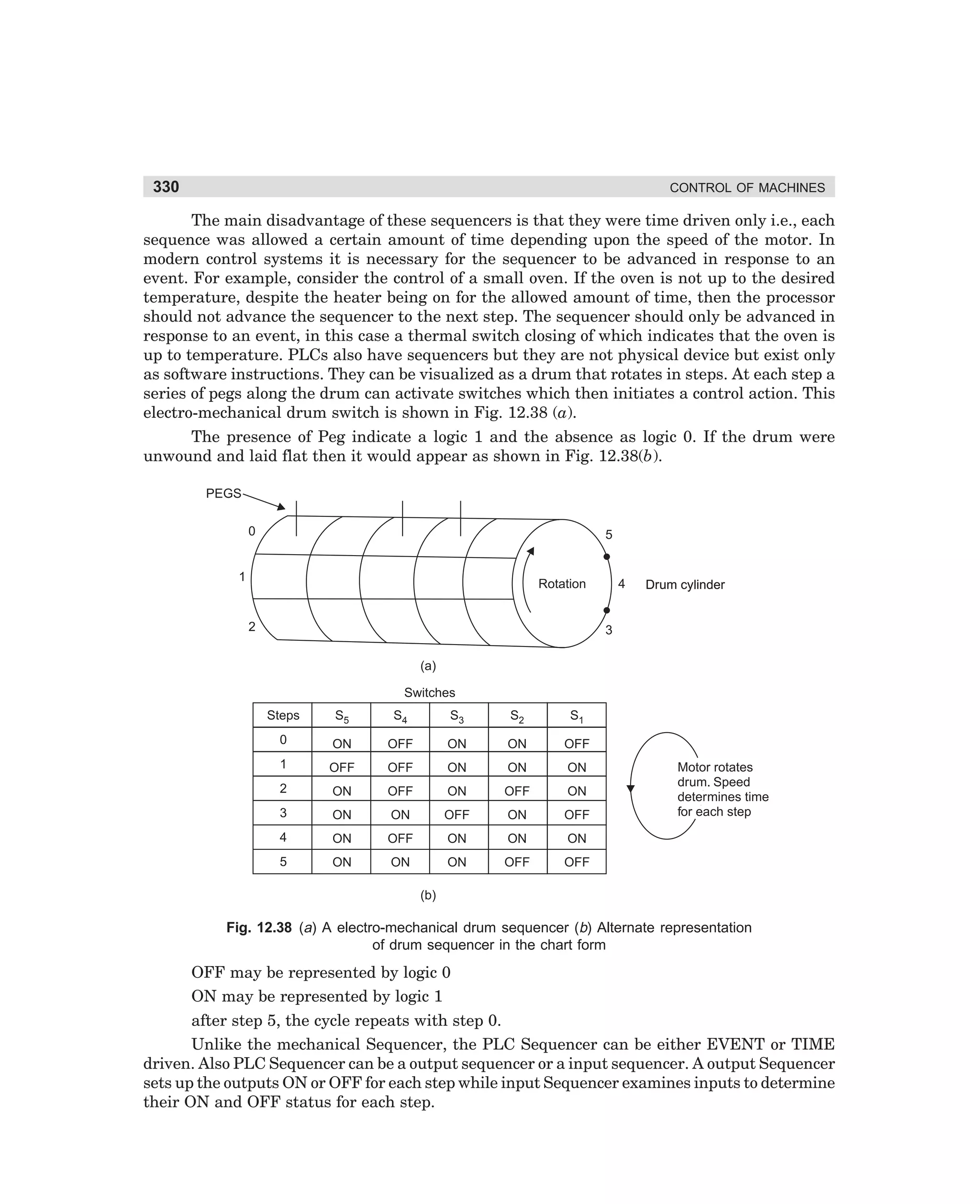
Fig. 3.7 Automatic primary resistor type starter (a) Power diagram (b) Control diagram
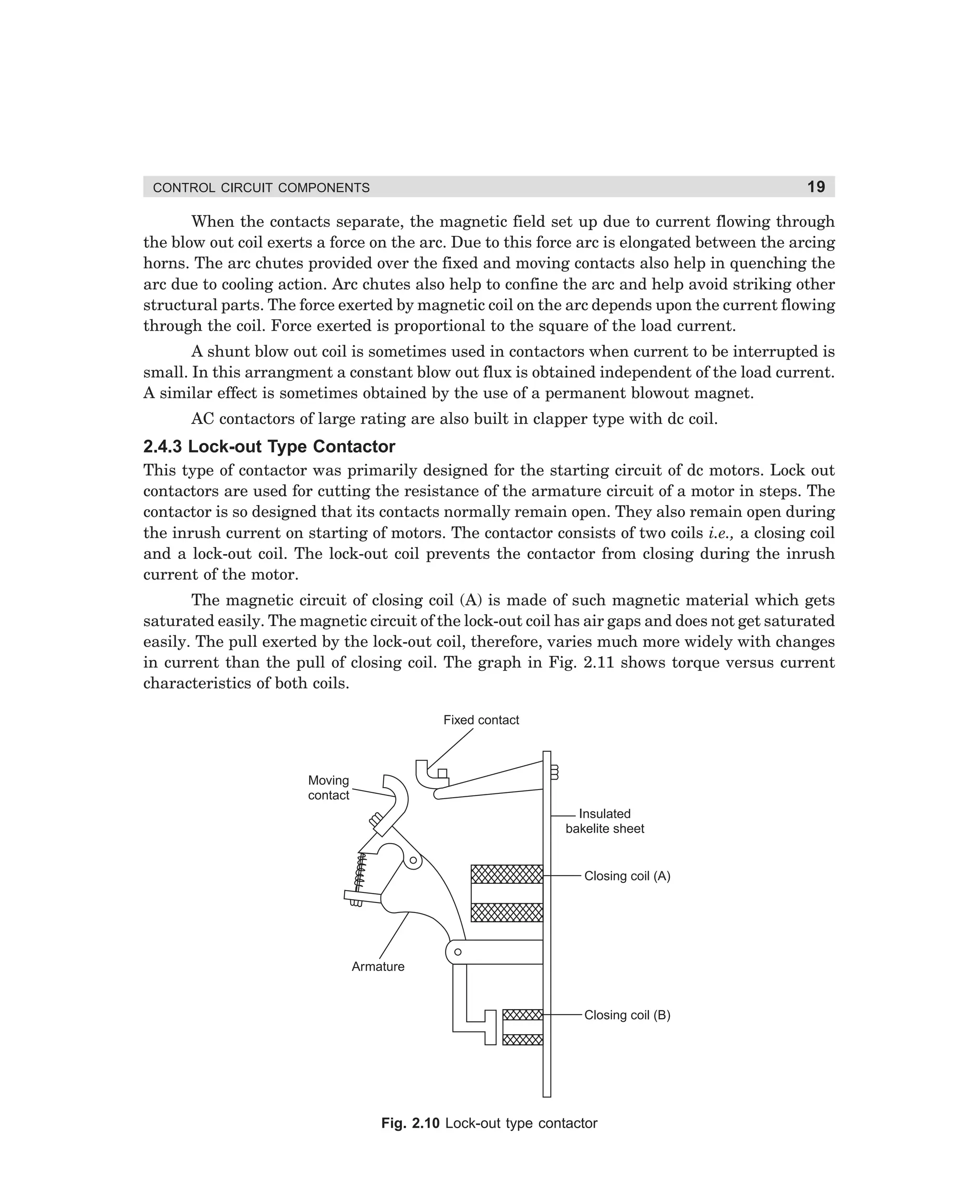
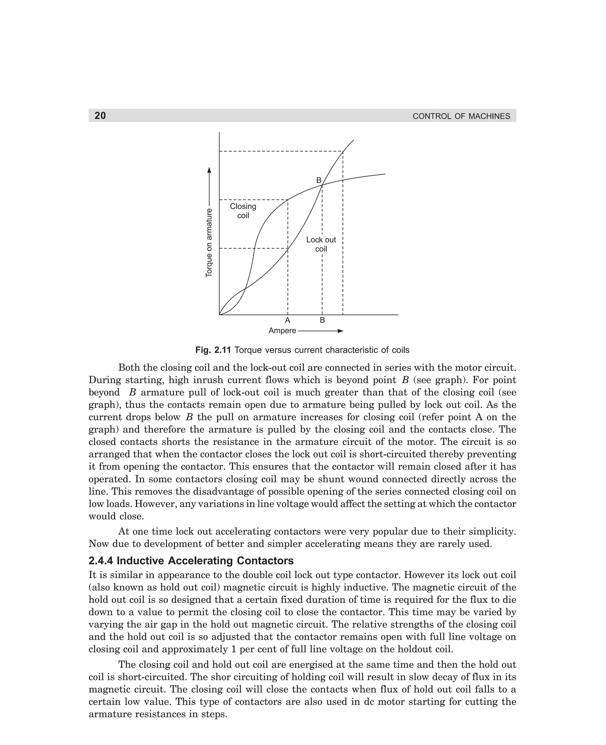
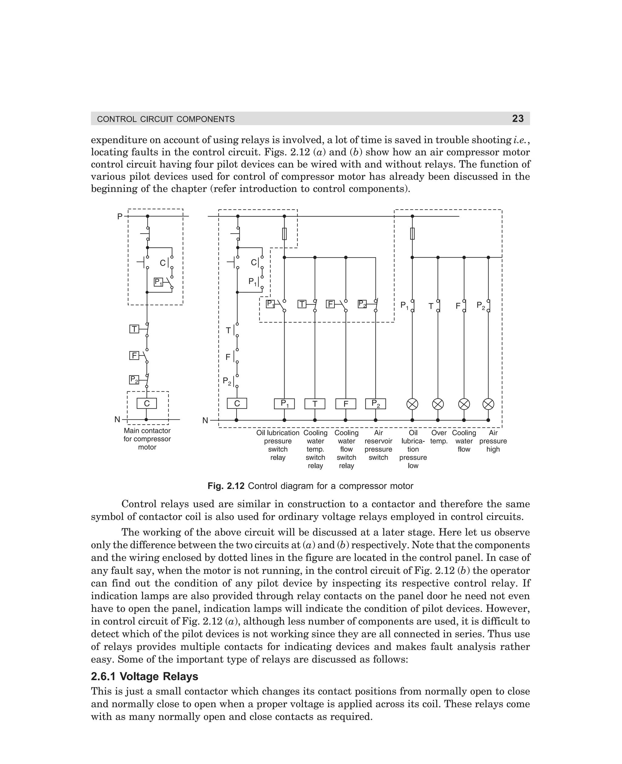
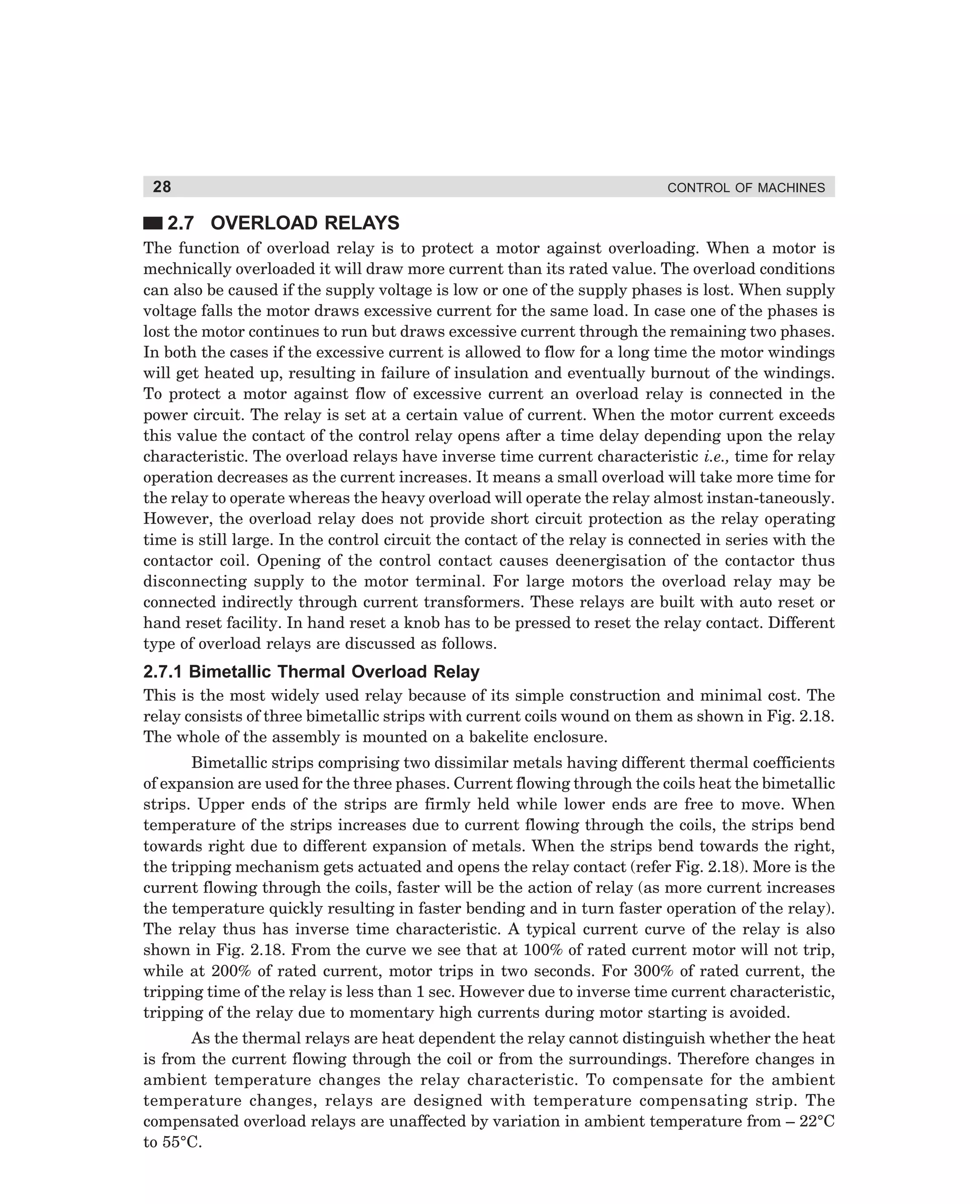
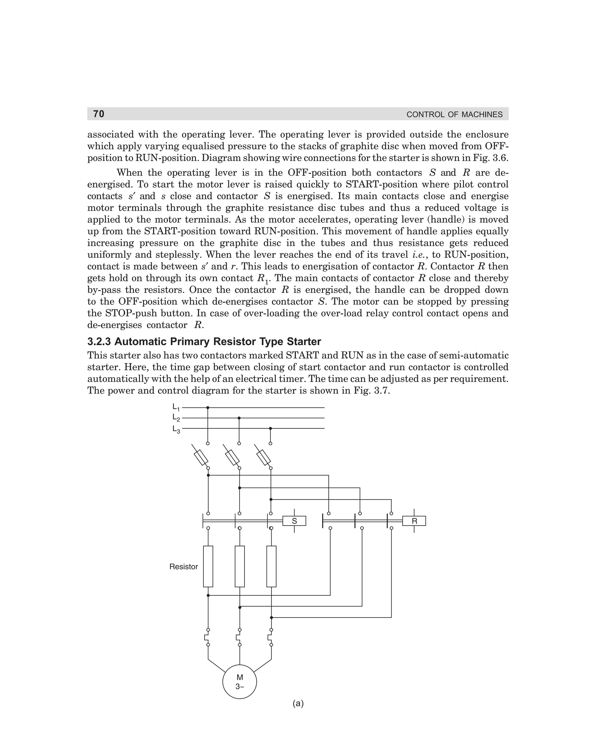
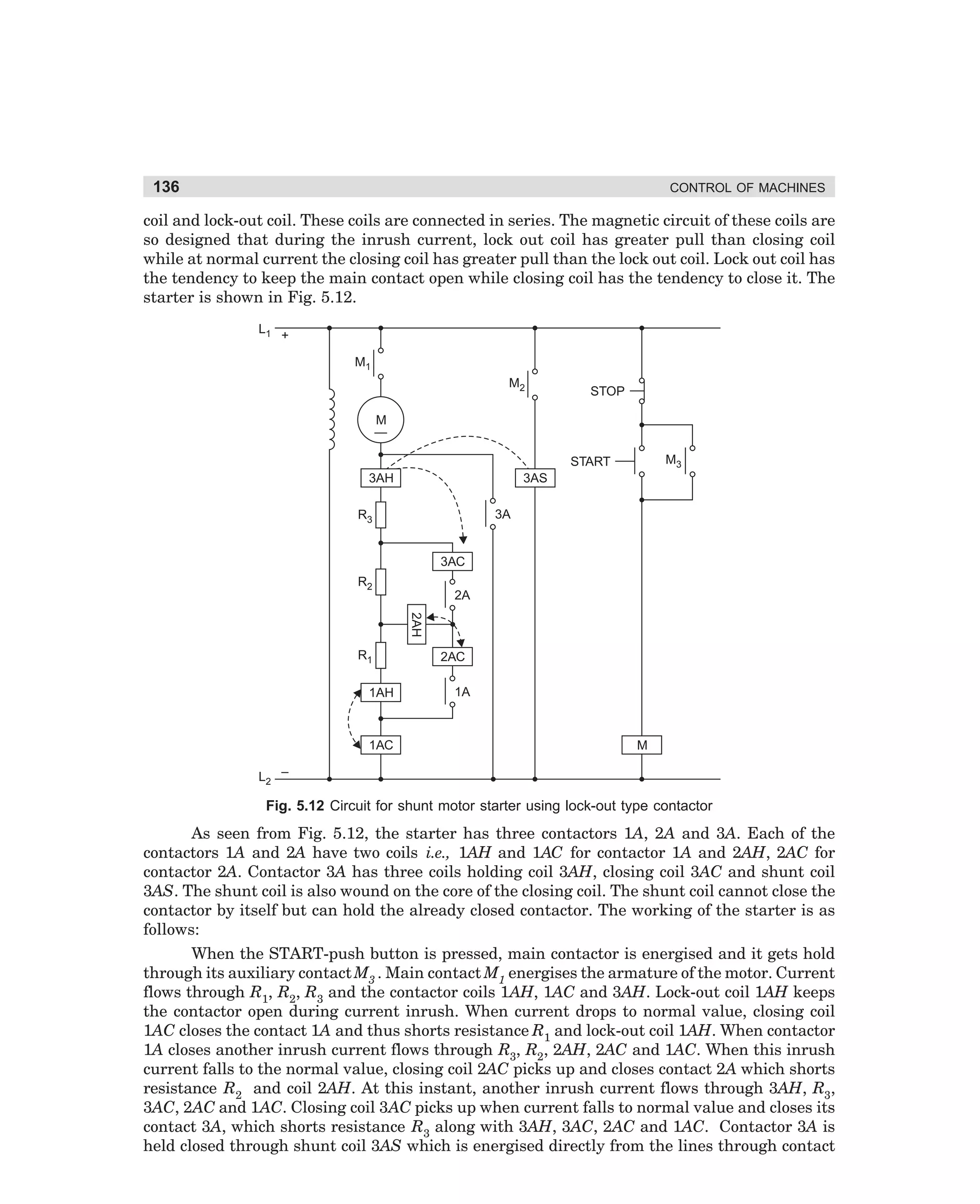
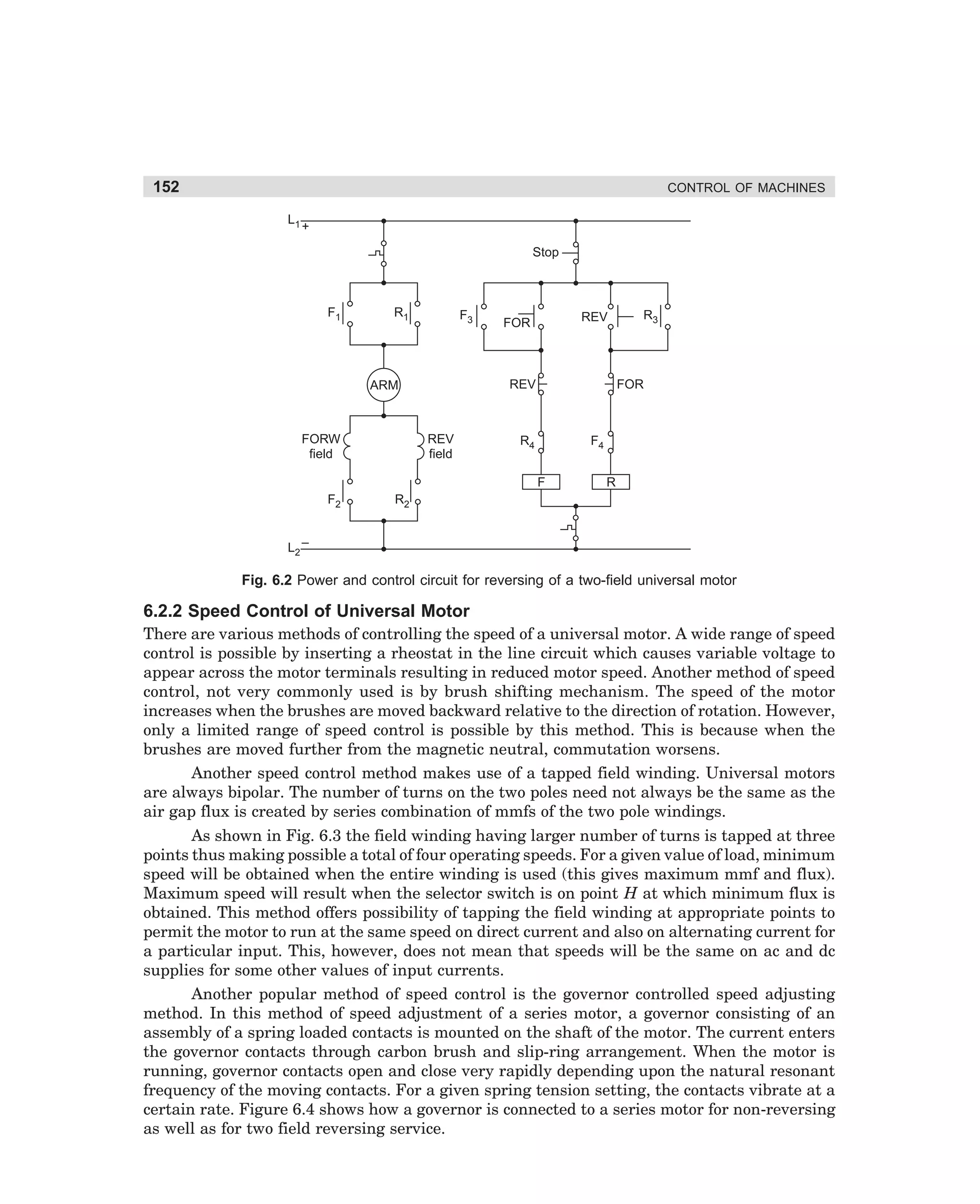
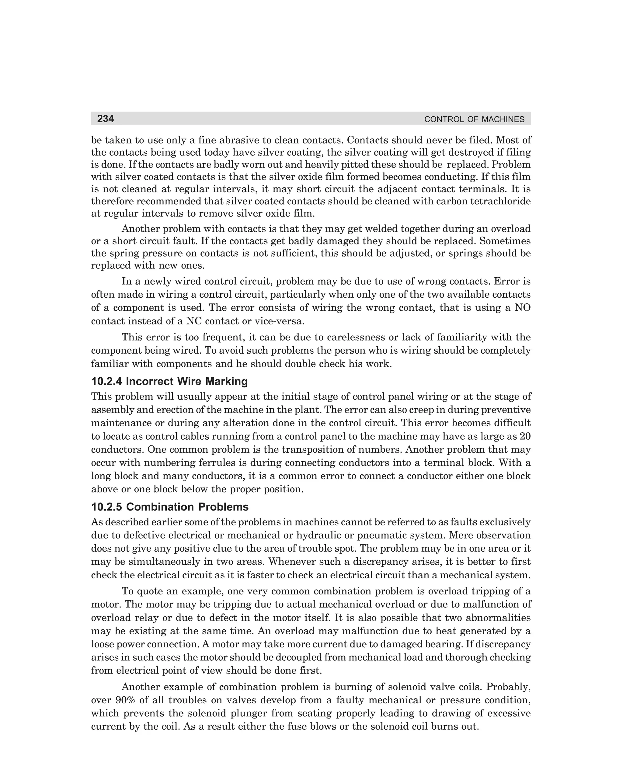
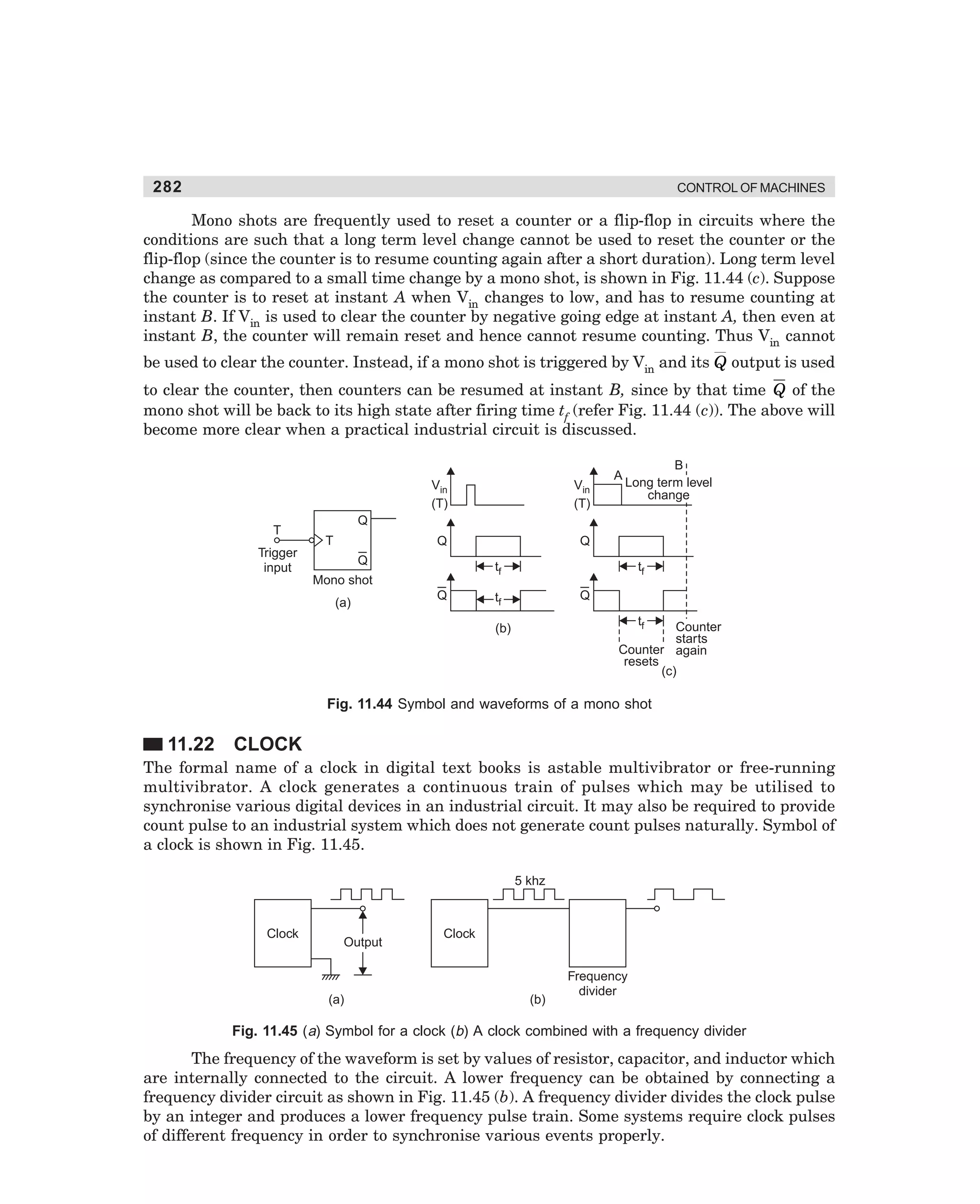
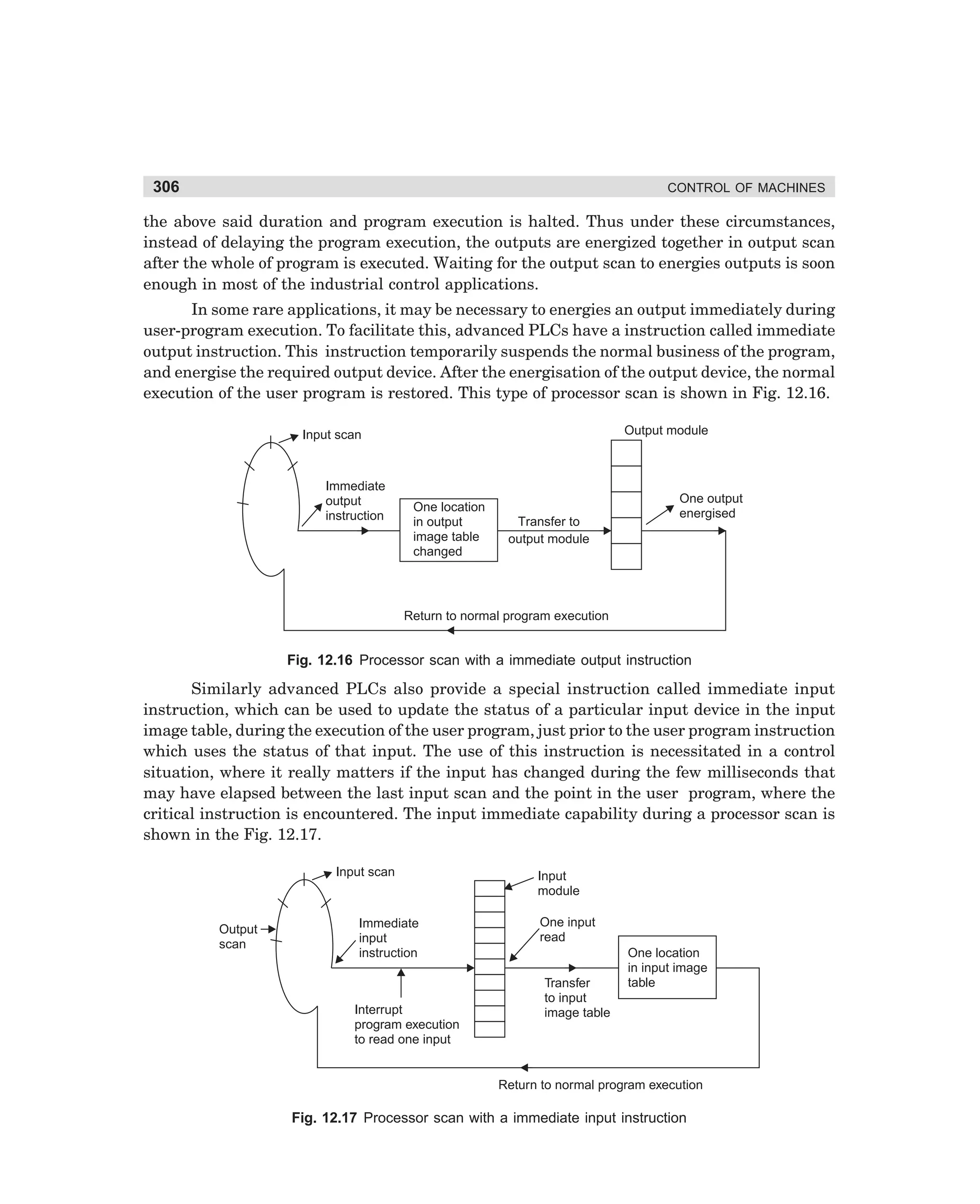
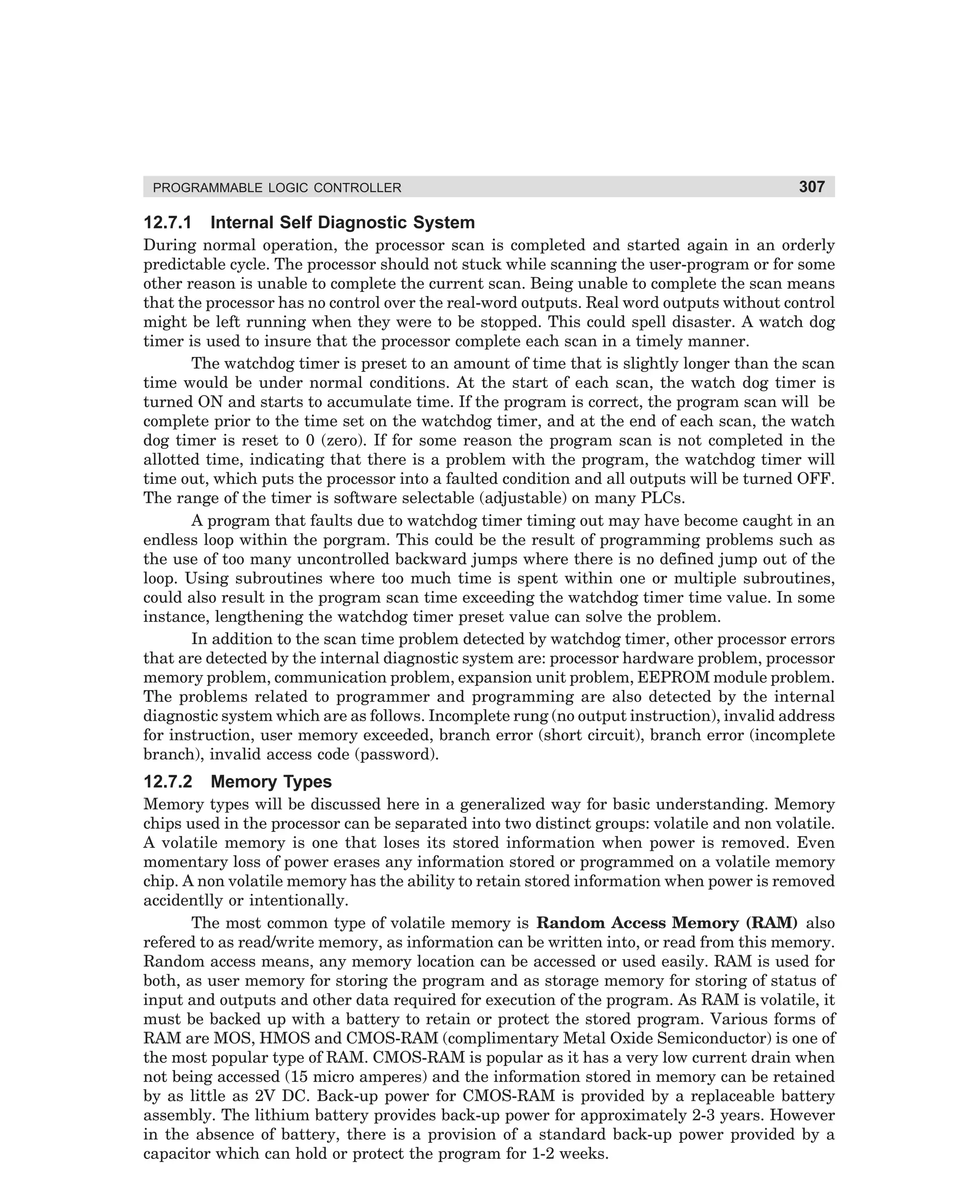
When ON-push button is pressed the control relay CR gets energised and is held
energised through its contact CR1, the over-load relay contact being in closed condition.
Normally open contact CR2 also closes and energises the rest of control circuit. Closing of
CR2 energises contactor S and the time delay relay TR through normally closed contact R1
of contactor R. Energisation of contactor S causes the main contacts to close and the motor
starts running with resistance connected in series with the supply lines [see Fig. 3.7 (a)].
When the time delay relay TR operates after a pre-set time, its delayed contact TR1 closes
and thereby energises the run contactor R. Contactor R remains energised by getting supply
through its own contact R2. Closing of contactor R short circuits the resistances and the
motor gets supply through the closed contacts of contactor R. The energisation of contactor
R causes switching off of start contactor S and time delay relay TR. De-energisation of
contactor S disconnects resistors from main supply. Also opening of delayed contact TR1 of
time delay relay TR does not effect the working of the run contactor as it is now held
through its own contact. The time set on the time delay relay determines the acceleration
time of the motor with resistors in circuit. This time can be increased or decreased depending
upon the load on the machines.
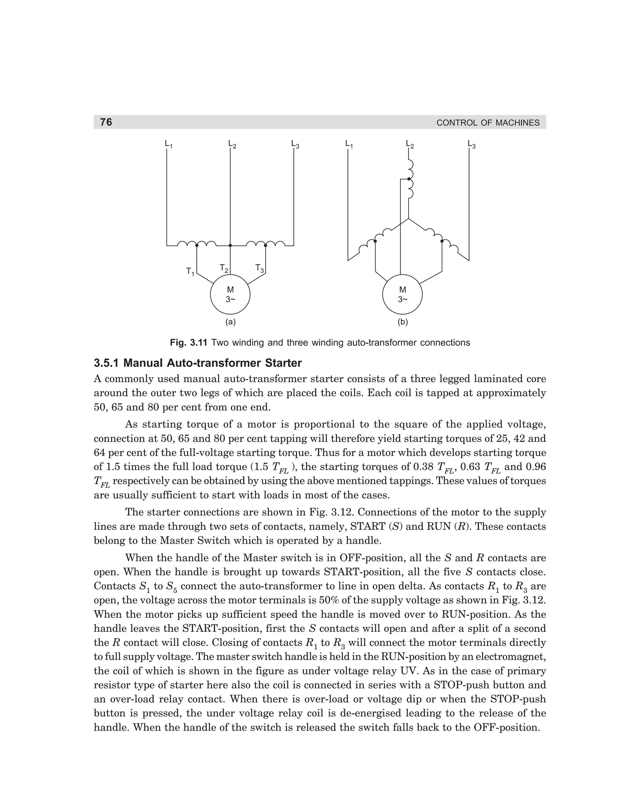
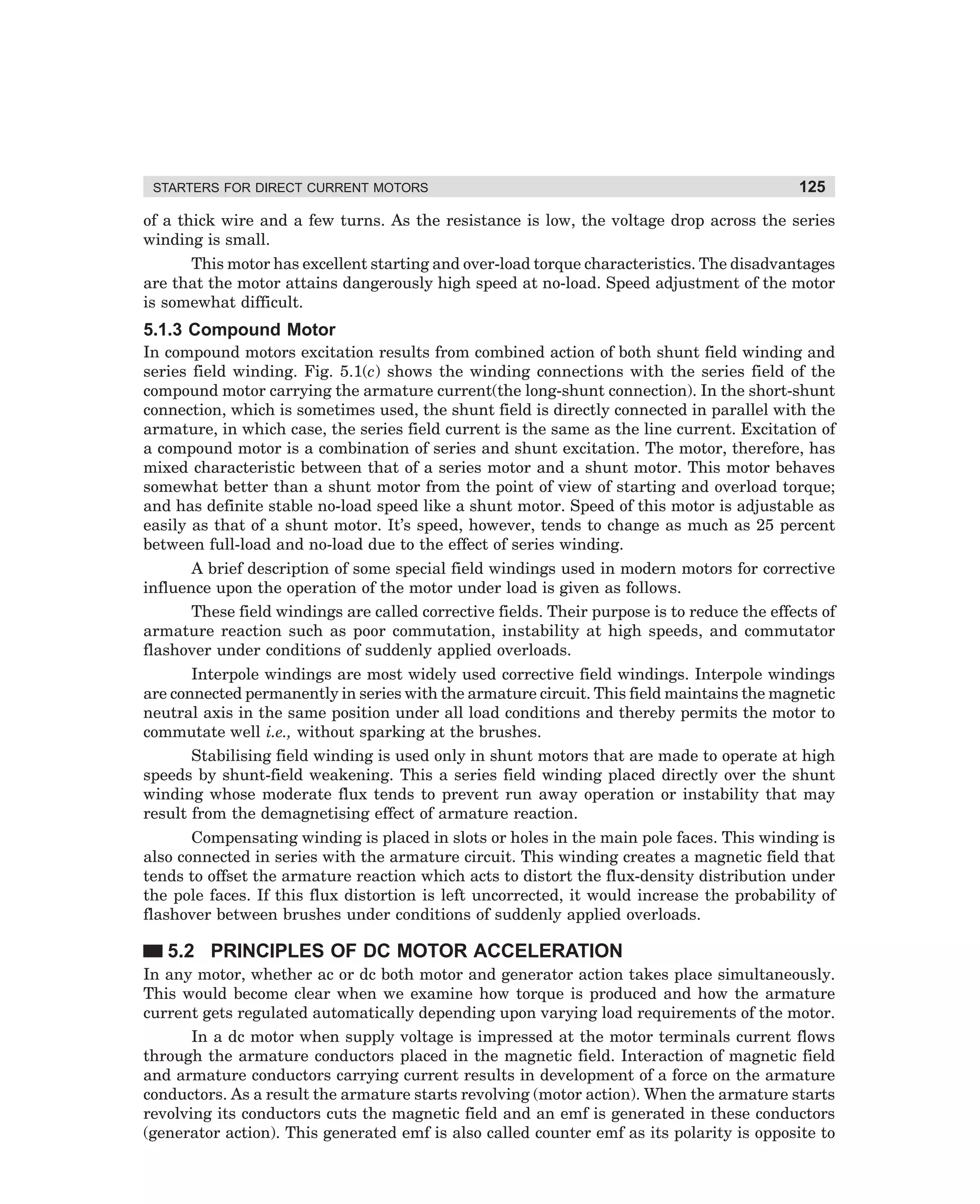
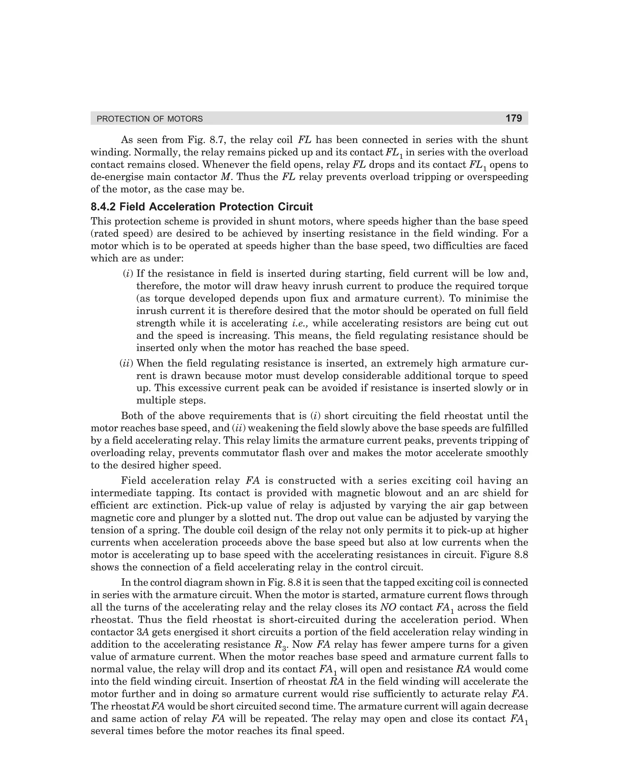
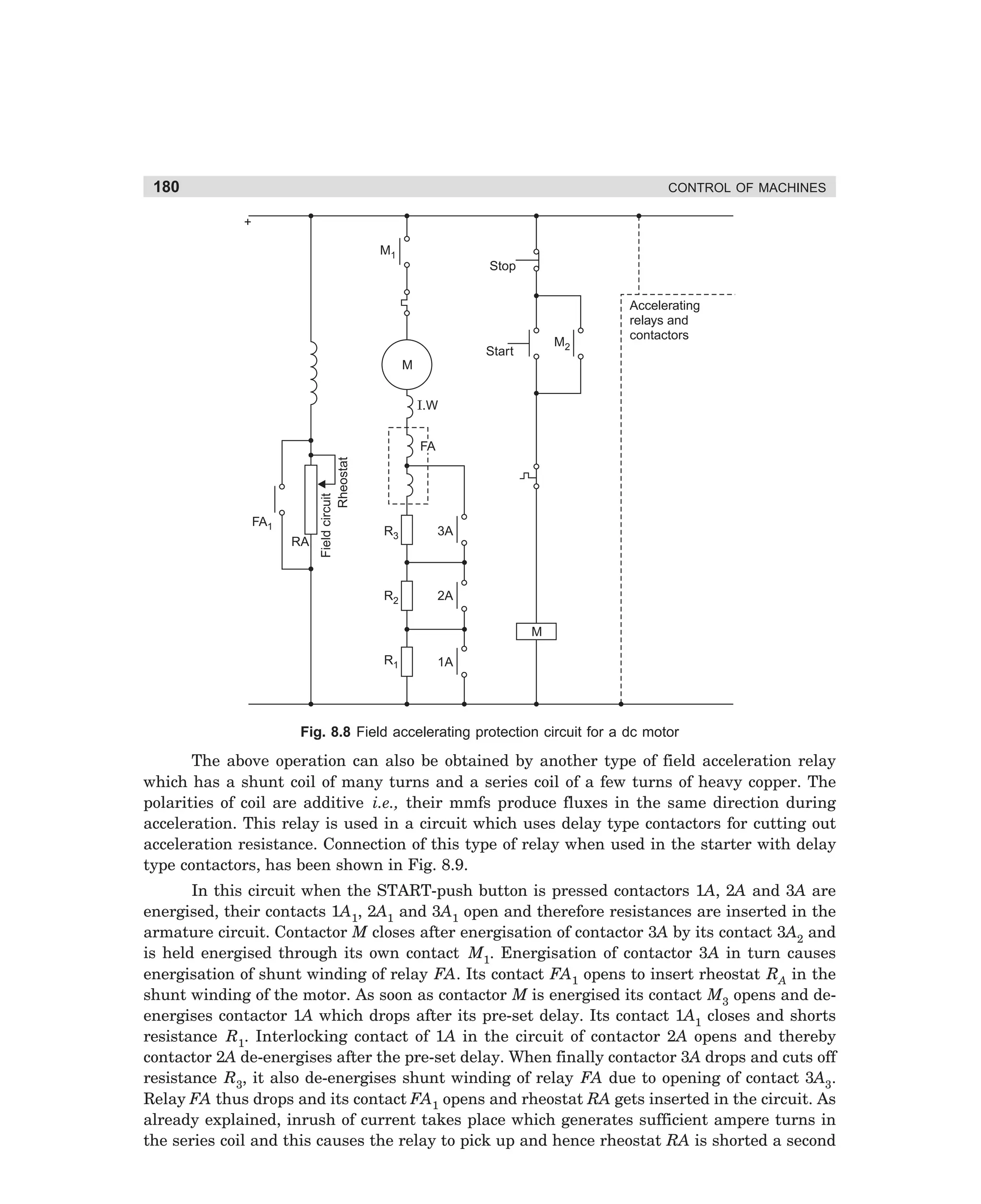
3.3 INCREMENT RESISTANCE STARTER
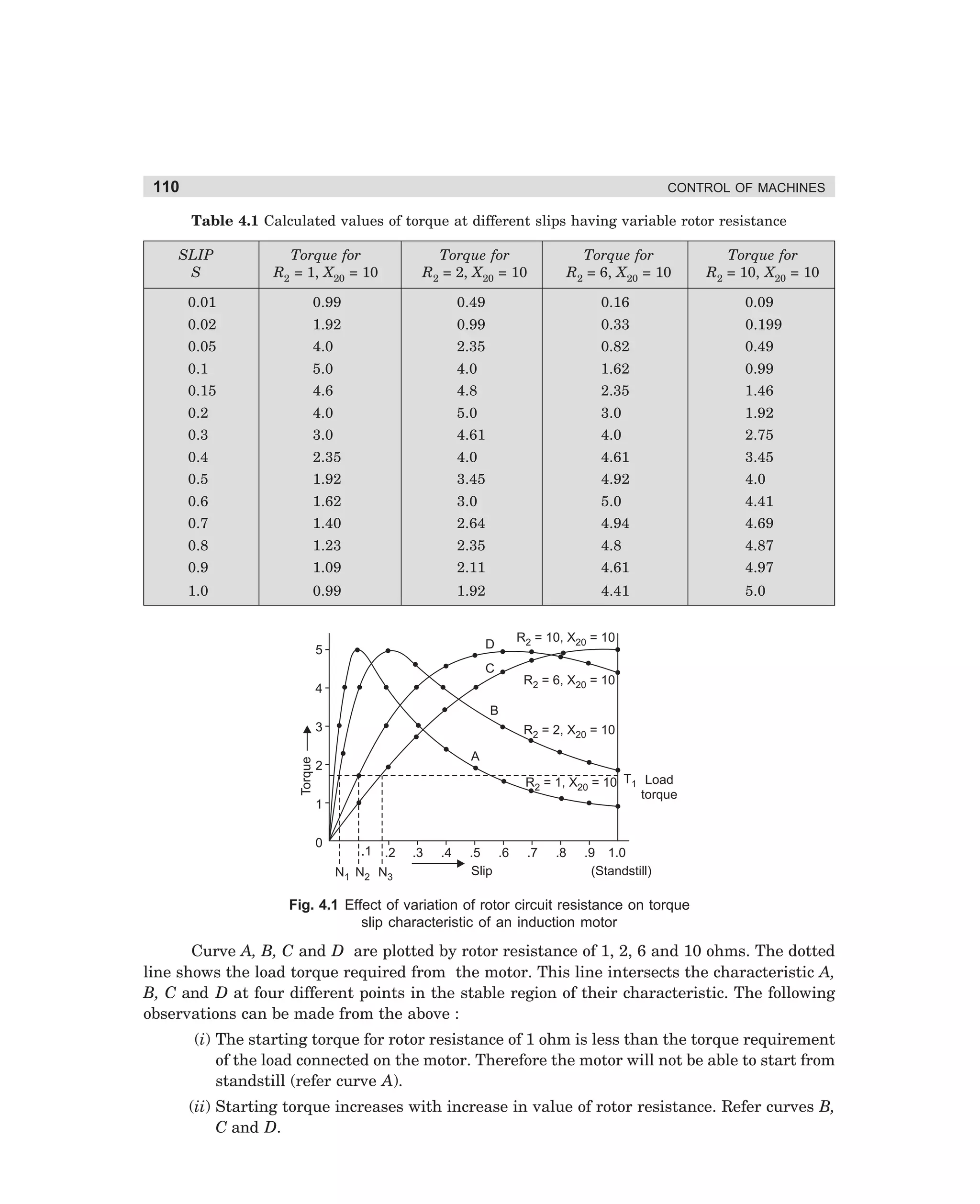
In increment resistance starter the resistance connected in the motor circuit is cut off in steps.
The motor starts only when all the resistances have been cut off and motor gets connected to
full supply voltage and draws the normal direct on line current, which is about six times the
full load current. At this point one may wonder, that what is then the need for inserting
resistance in the circuit and cut it off in increments till the motor again gets connected to
supply ! This starter is used for large motors which require high starting torque to start from
standstill. A reduced inrush current cannot start these motors from standstill. The current
required for starting such motors is the direct on line current. However, if this large current is
drawn by connecting the motor directly to supply, the supply network gets unstable. The voltage
regulators connected in the network cannot correct the voltage drop due to this sudden heavy
current drawn from supply. In order to allow time for the voltage regulators to correct the
system network voltage, the direct on line inrush current from the supply is drawn in two or
three steps with certain fixed time delays. This time delay after each current inrush allows the
voltage regulators to adjust the network voltage. This would become more clear when we look
dharm
d:N-MachMac3-1.pm5
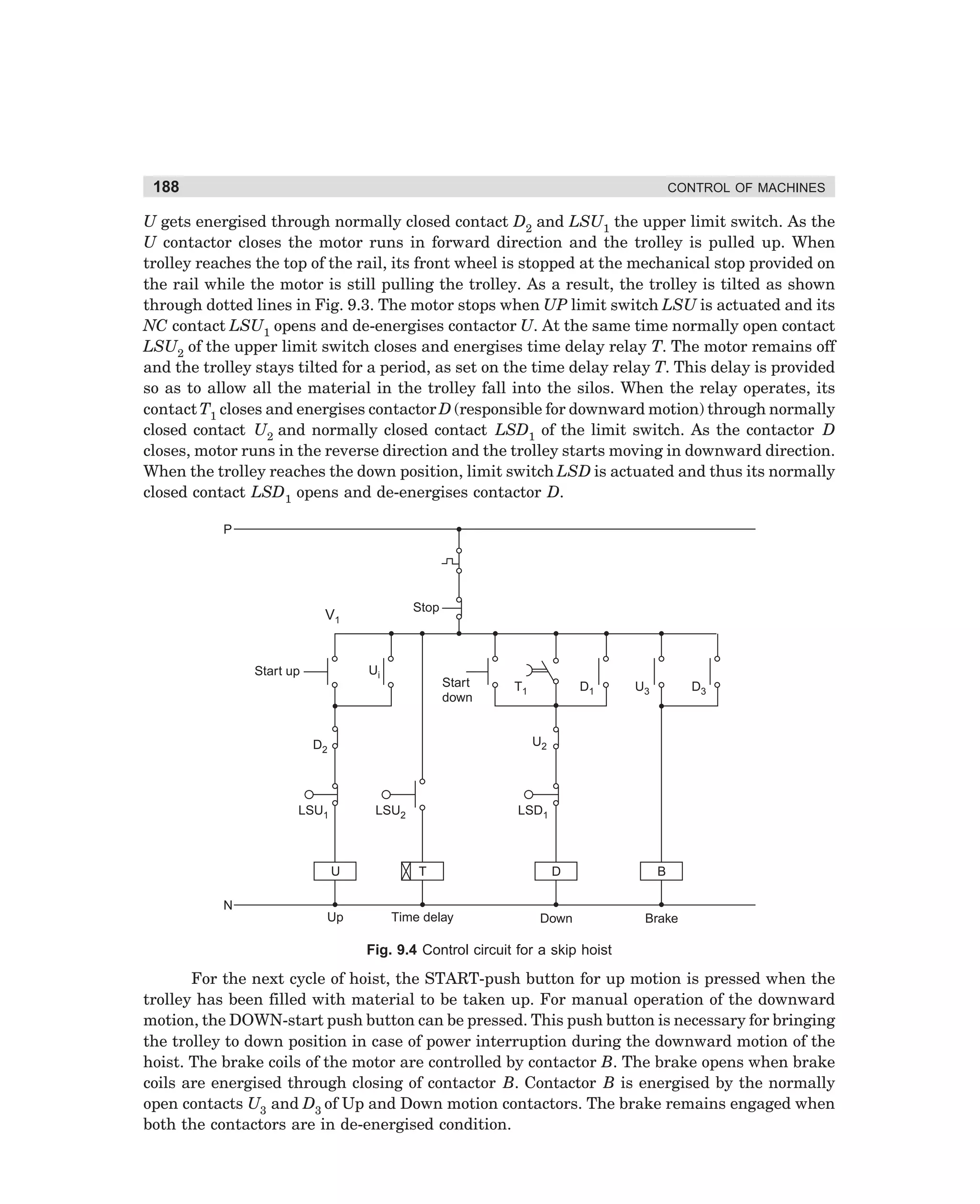
71](https://image.slidesharecdn.com/controlofmachines-130110181054-phpapp01-140107230436-phpapp02/75/Controlofmachines-130110181054-phpapp01-88-2048.jpg)
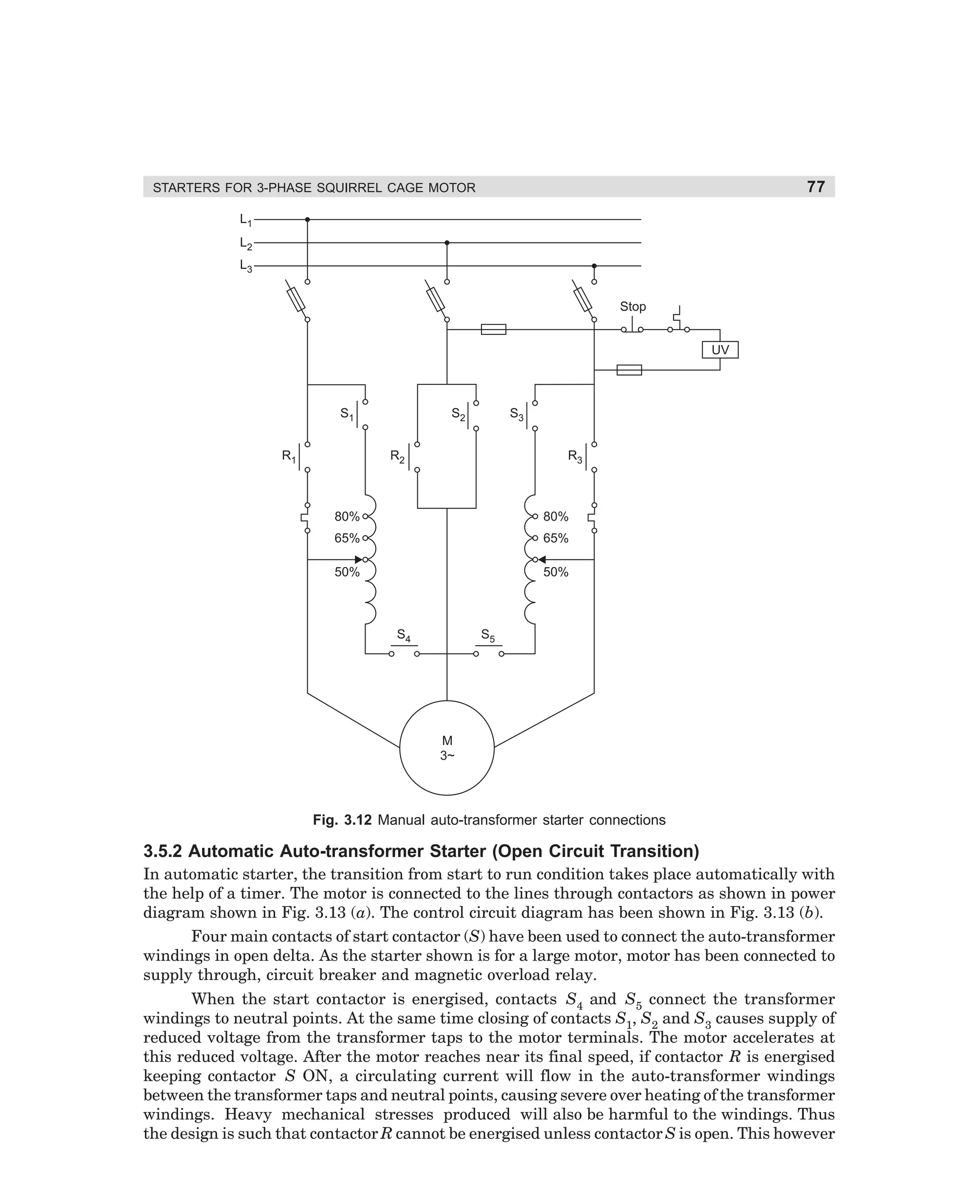
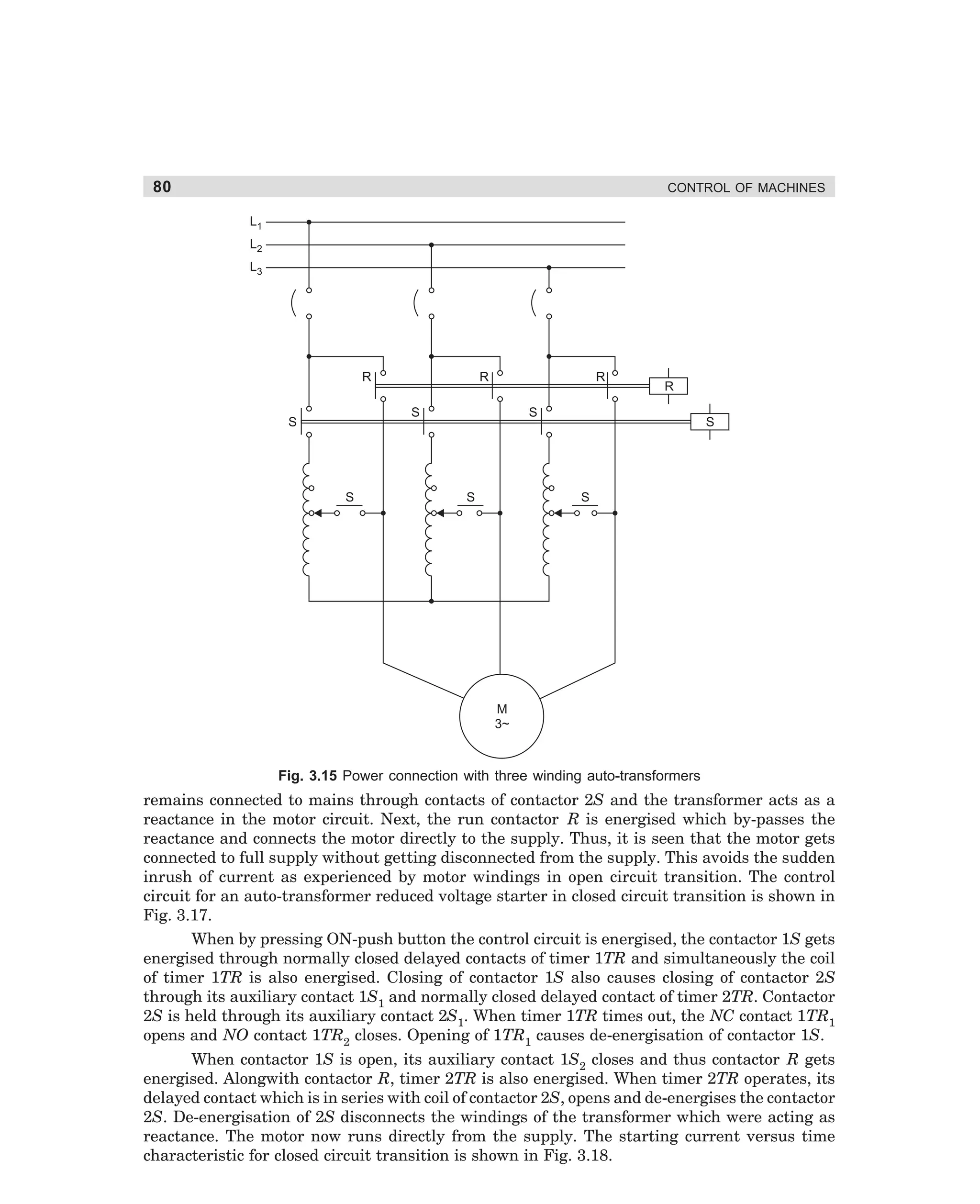
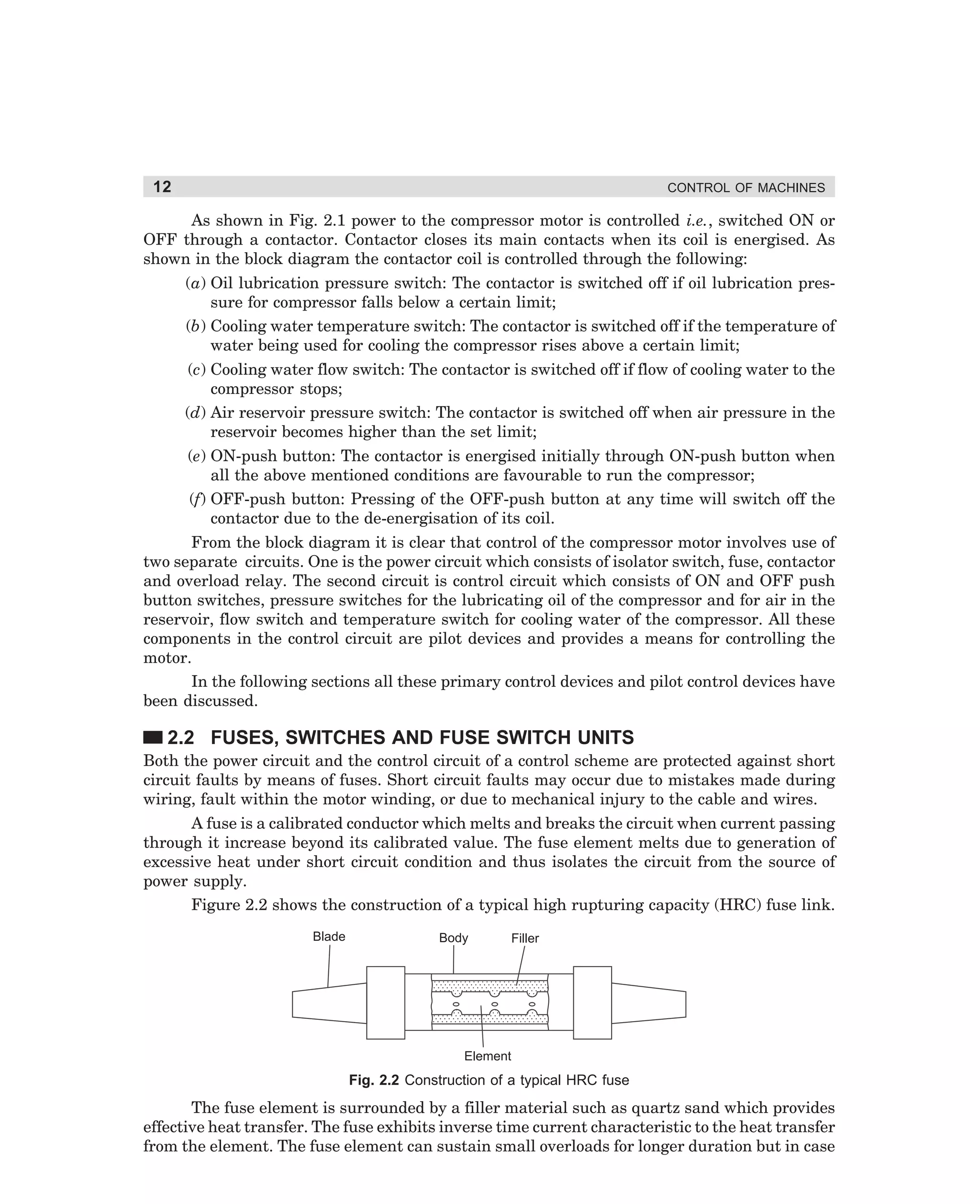
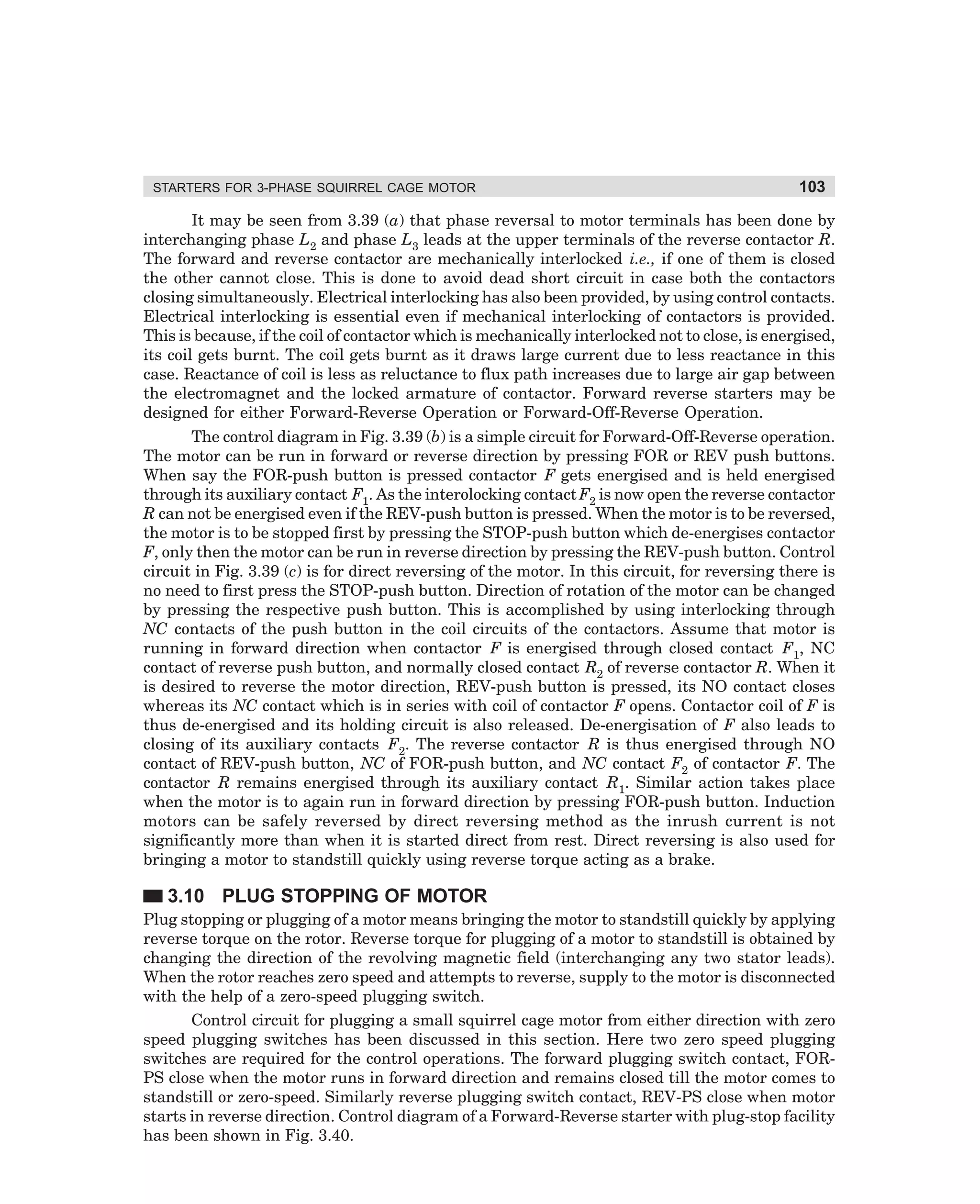
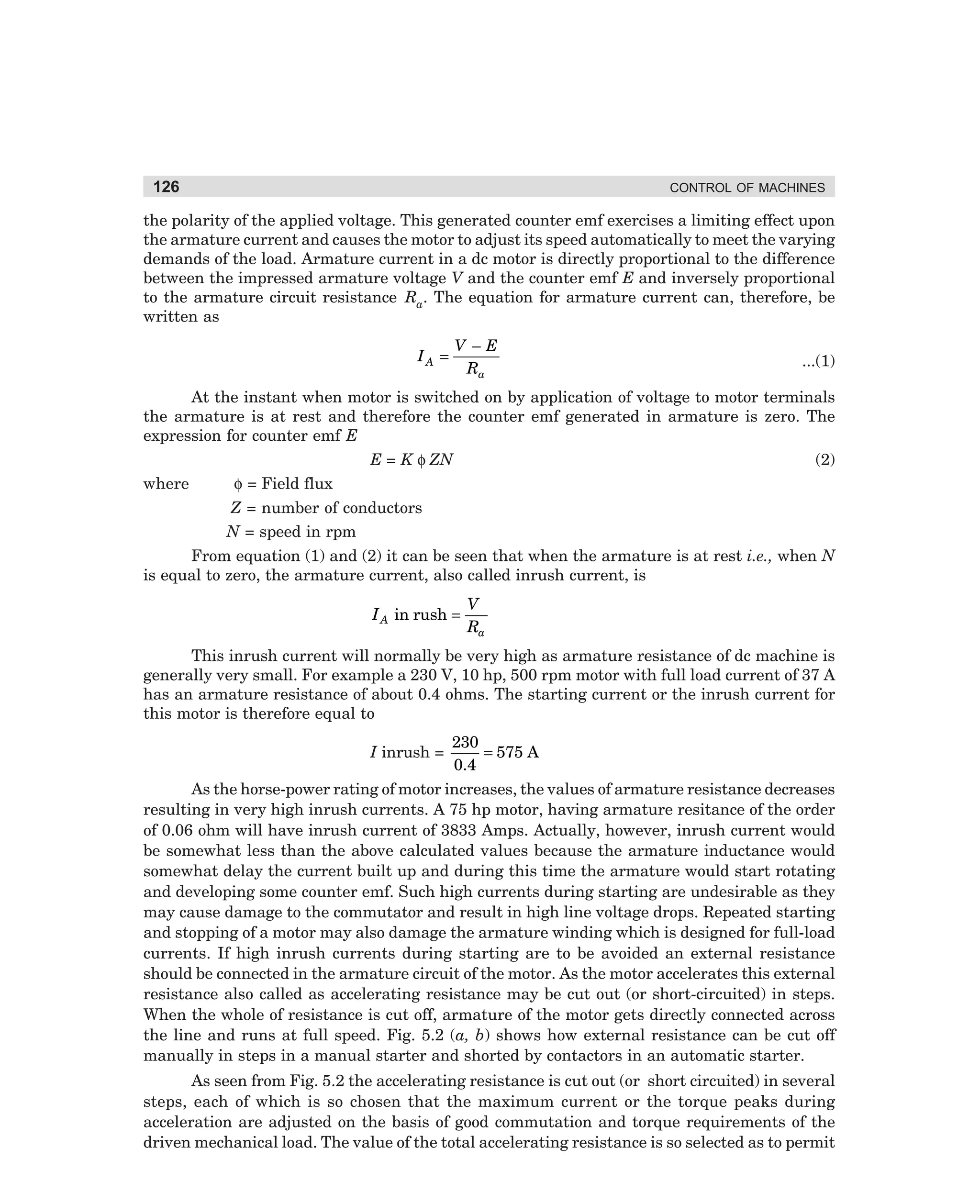
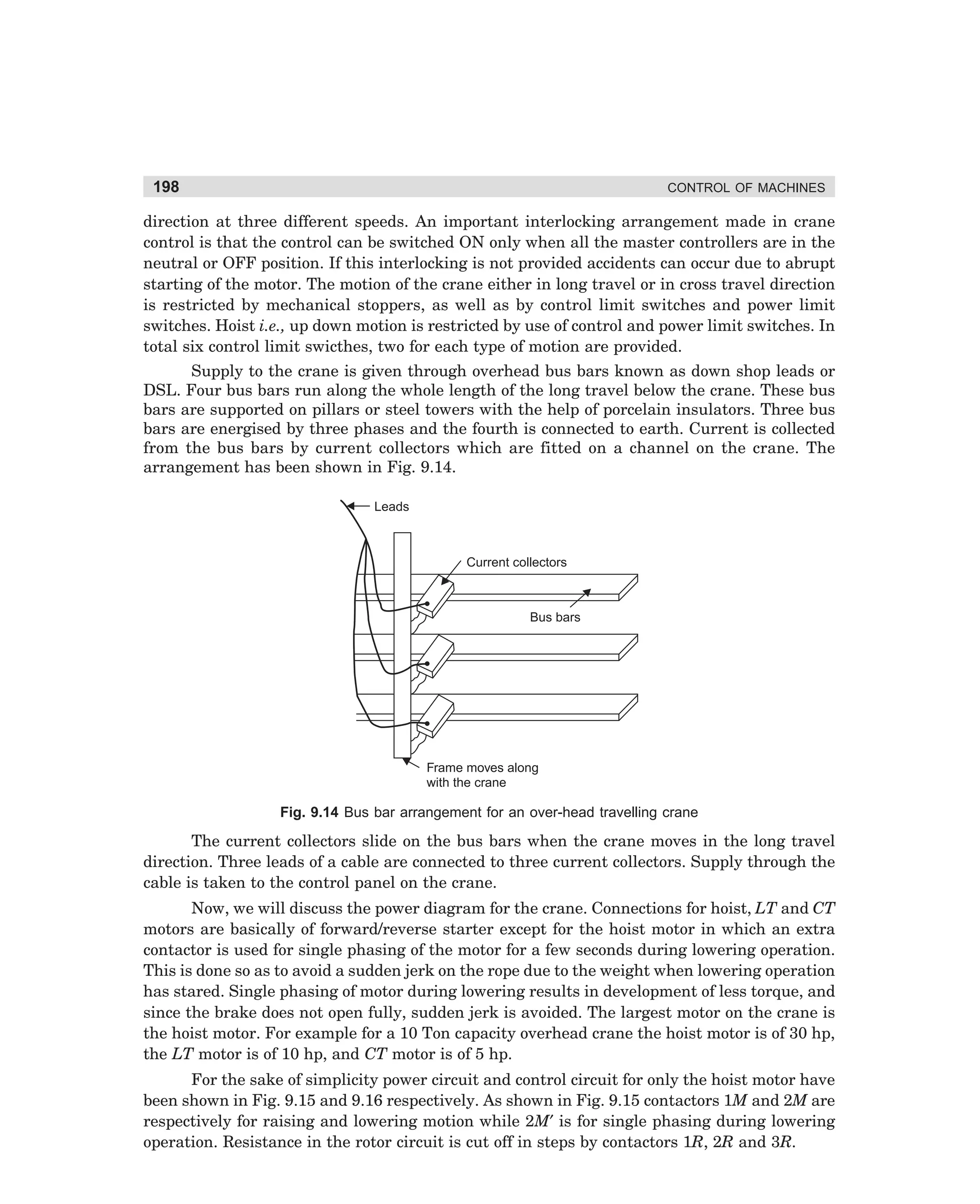
![93
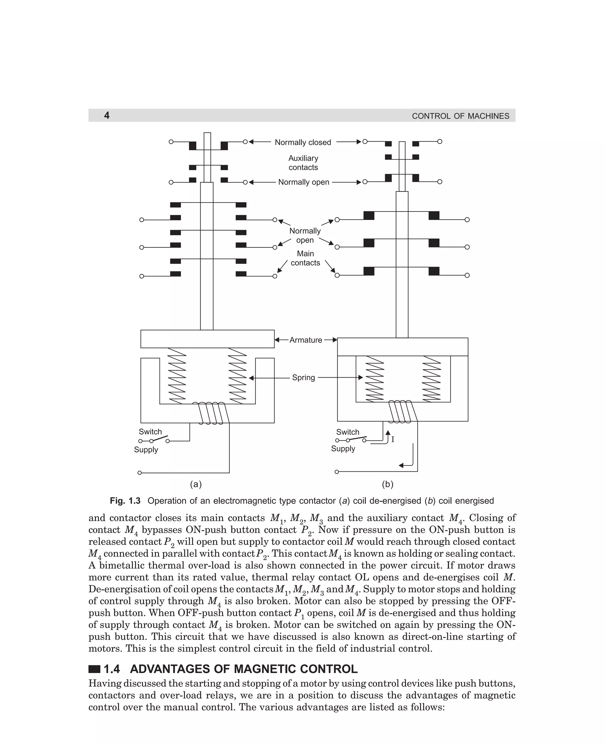
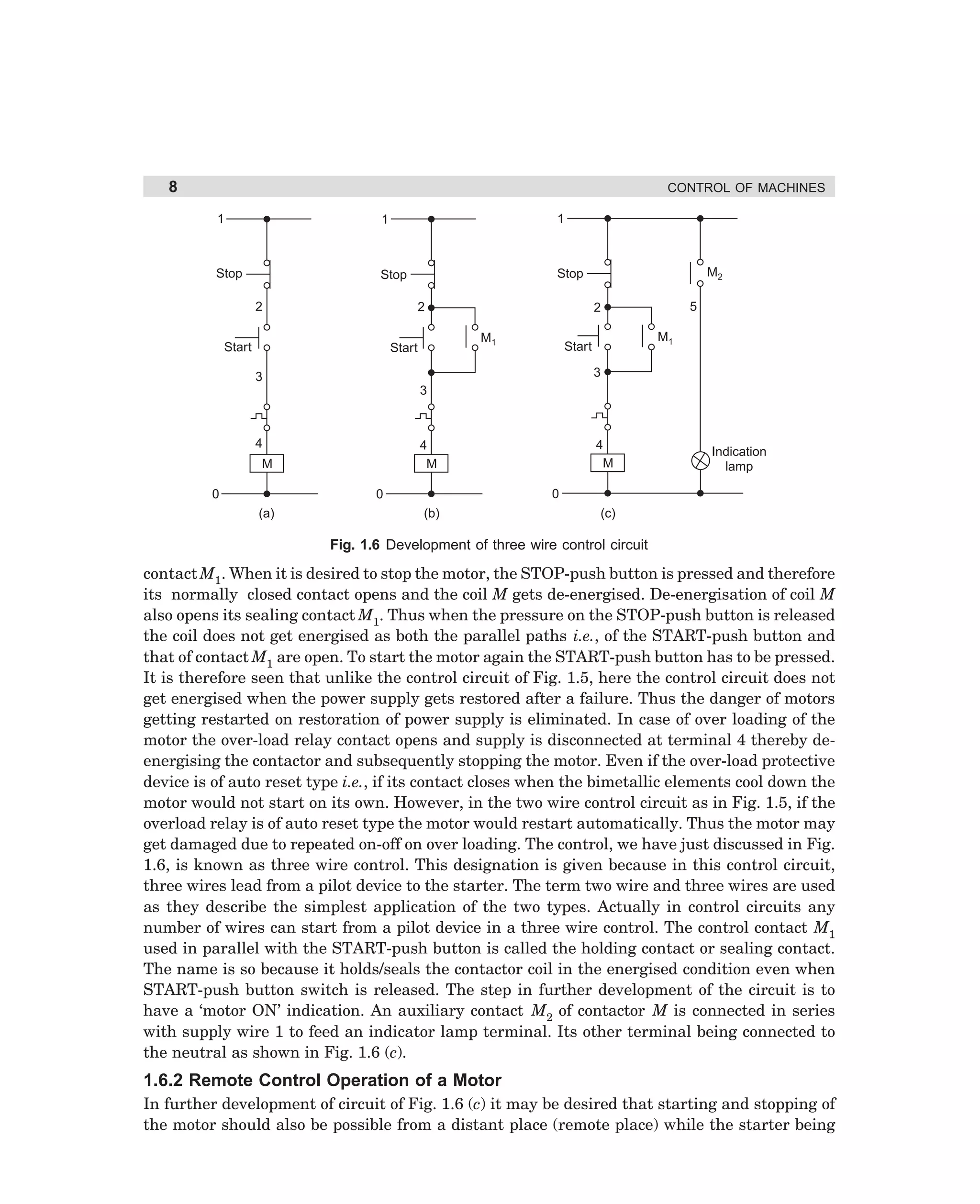
STARTERS FOR 3-PHASE SQUIRREL CAGE MOTOR
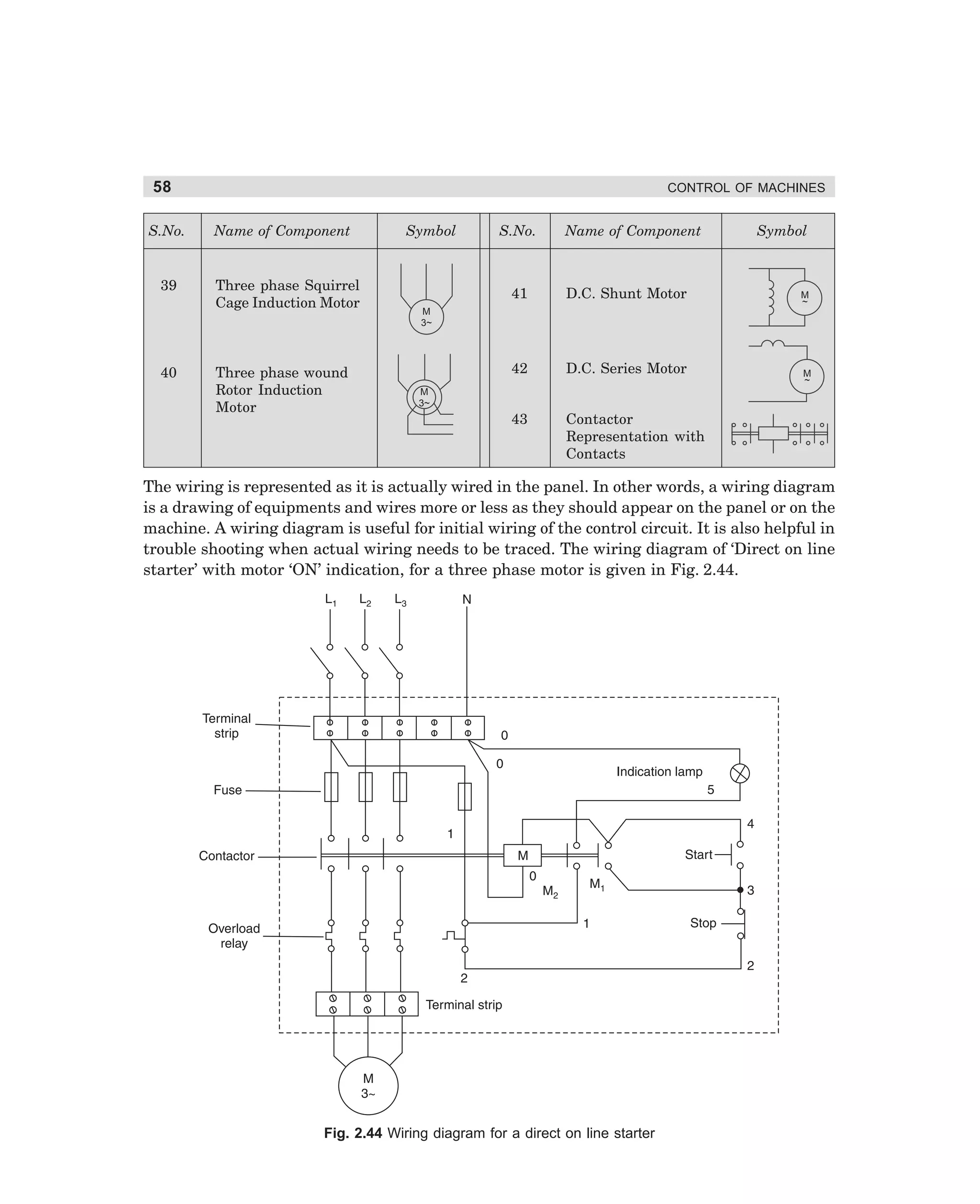
L1
L2
L3
D
T
M
A1
B1
C1
A2
B2
S
C2
Resistance
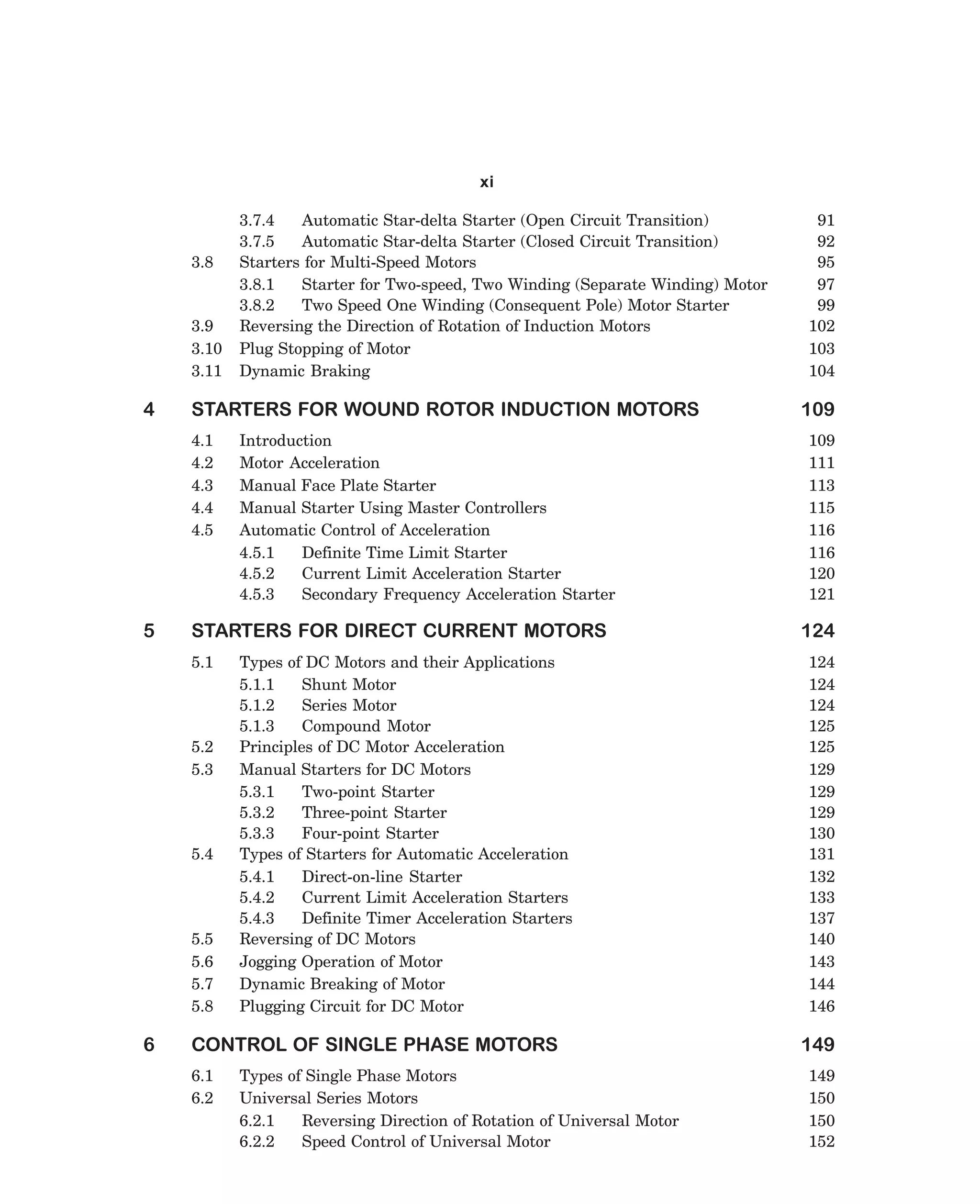
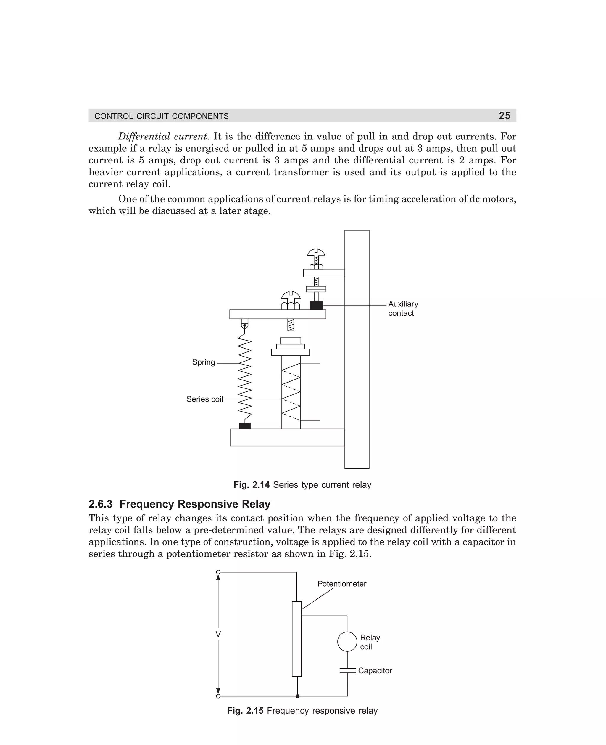
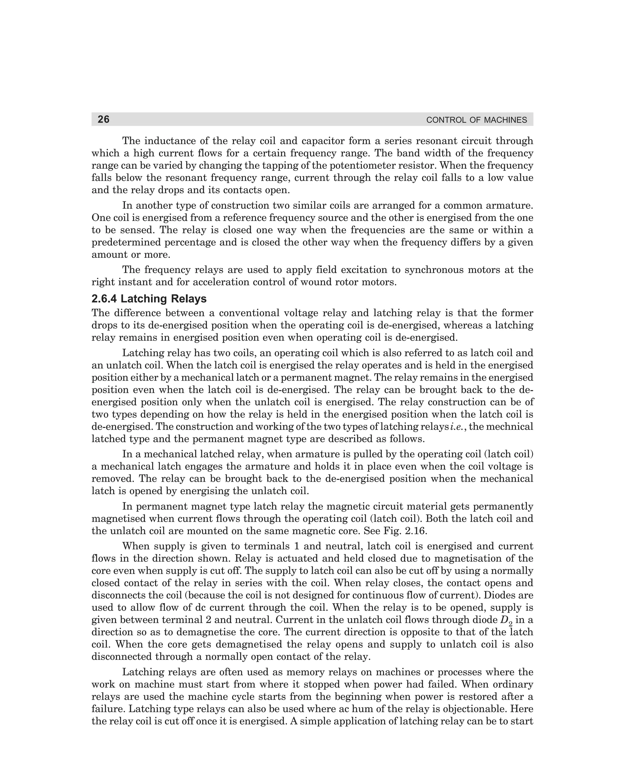
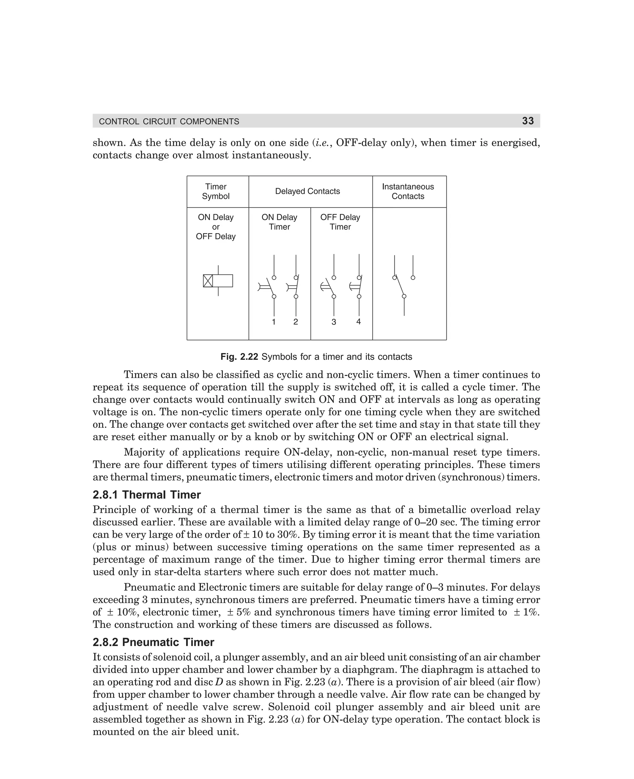
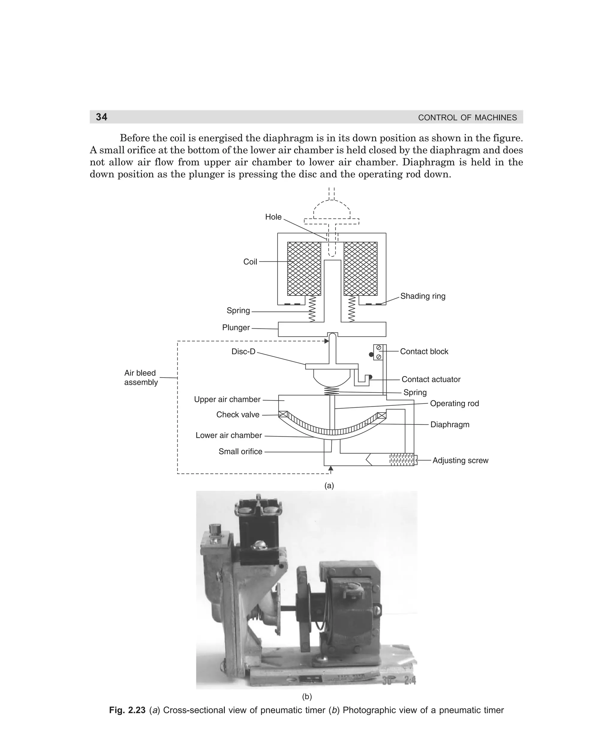
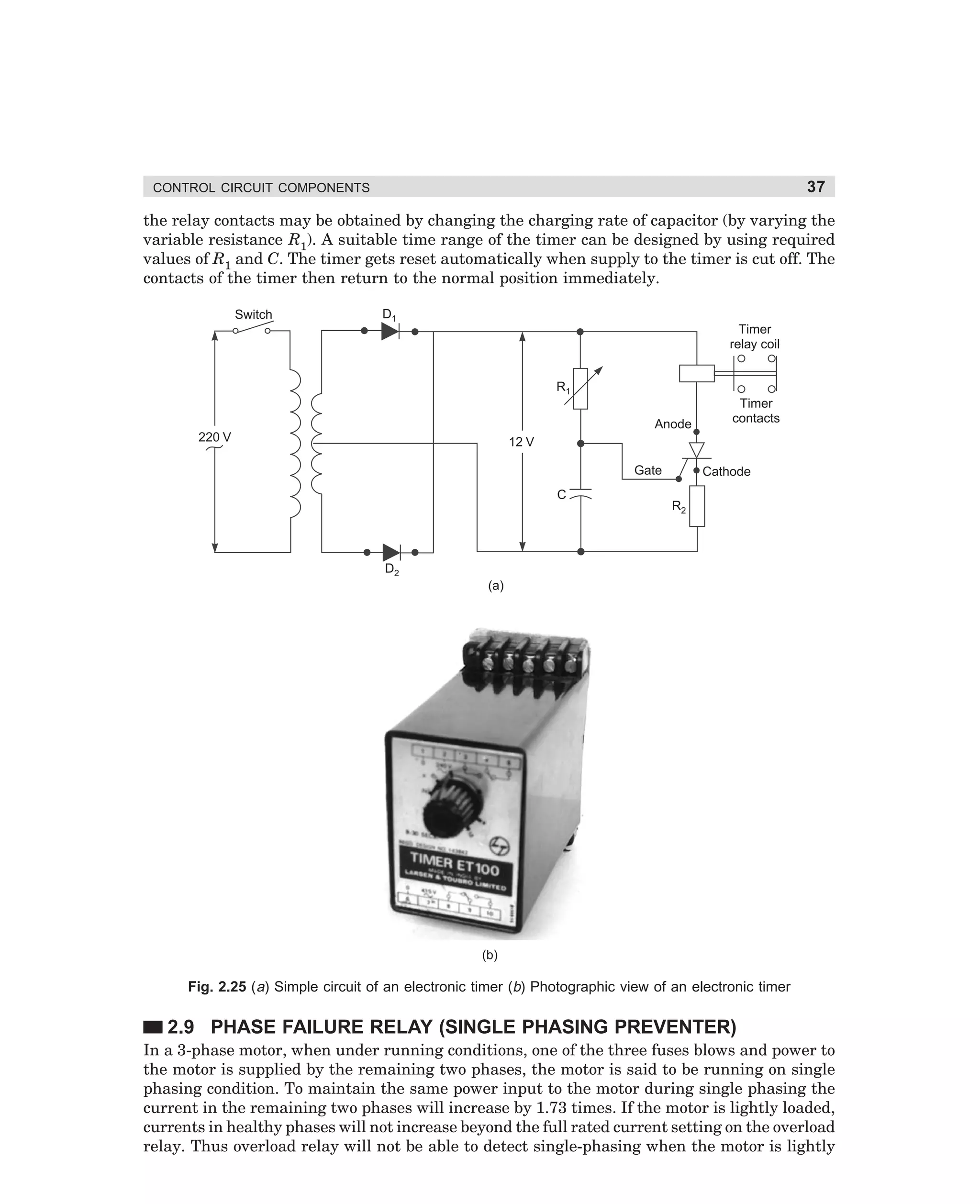
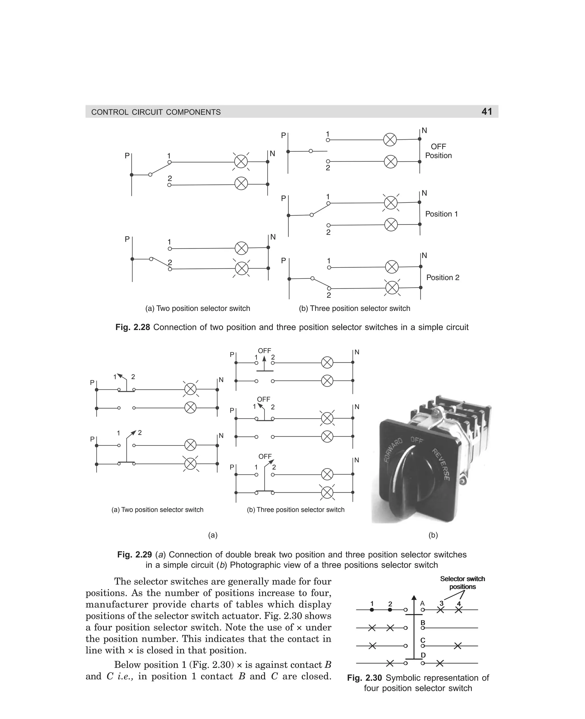
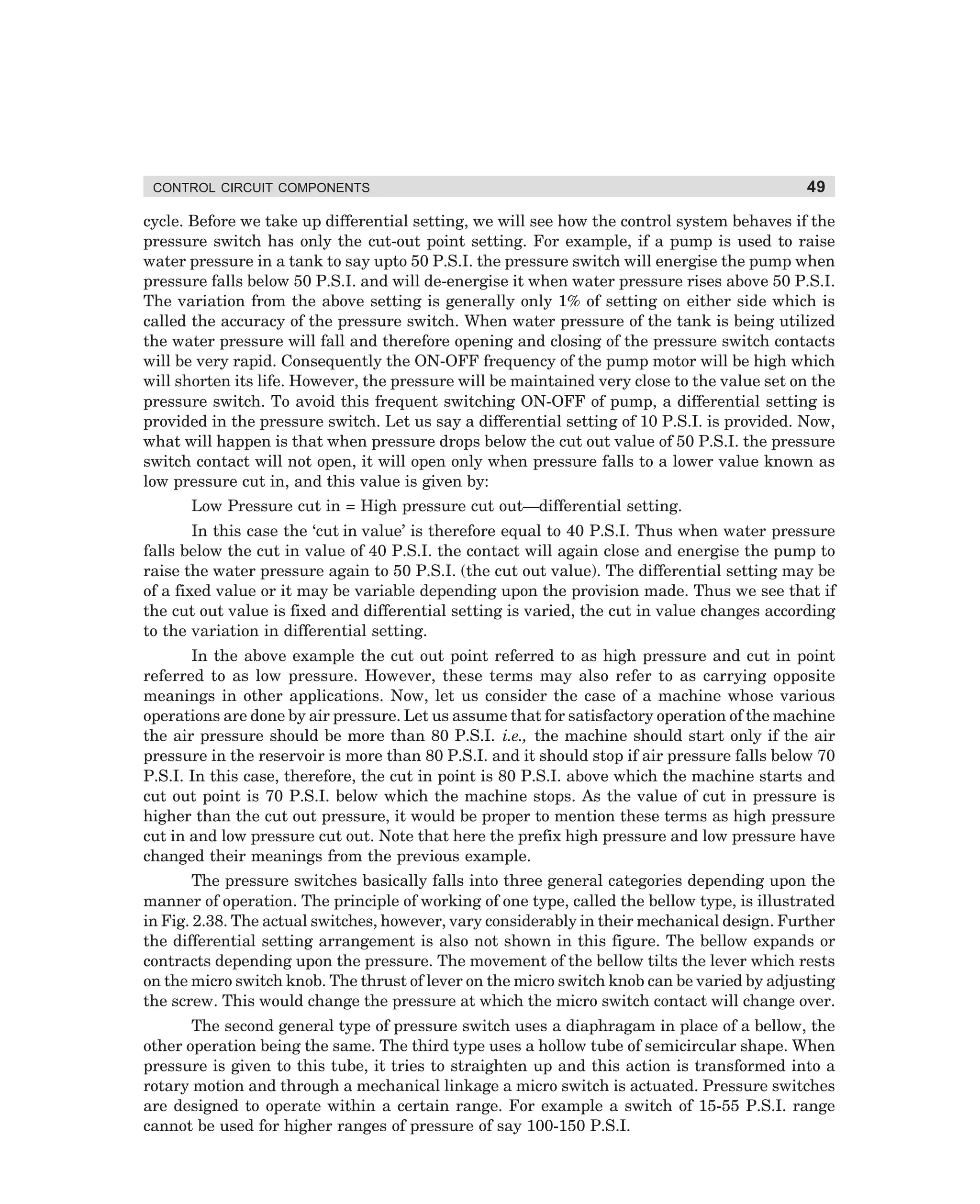
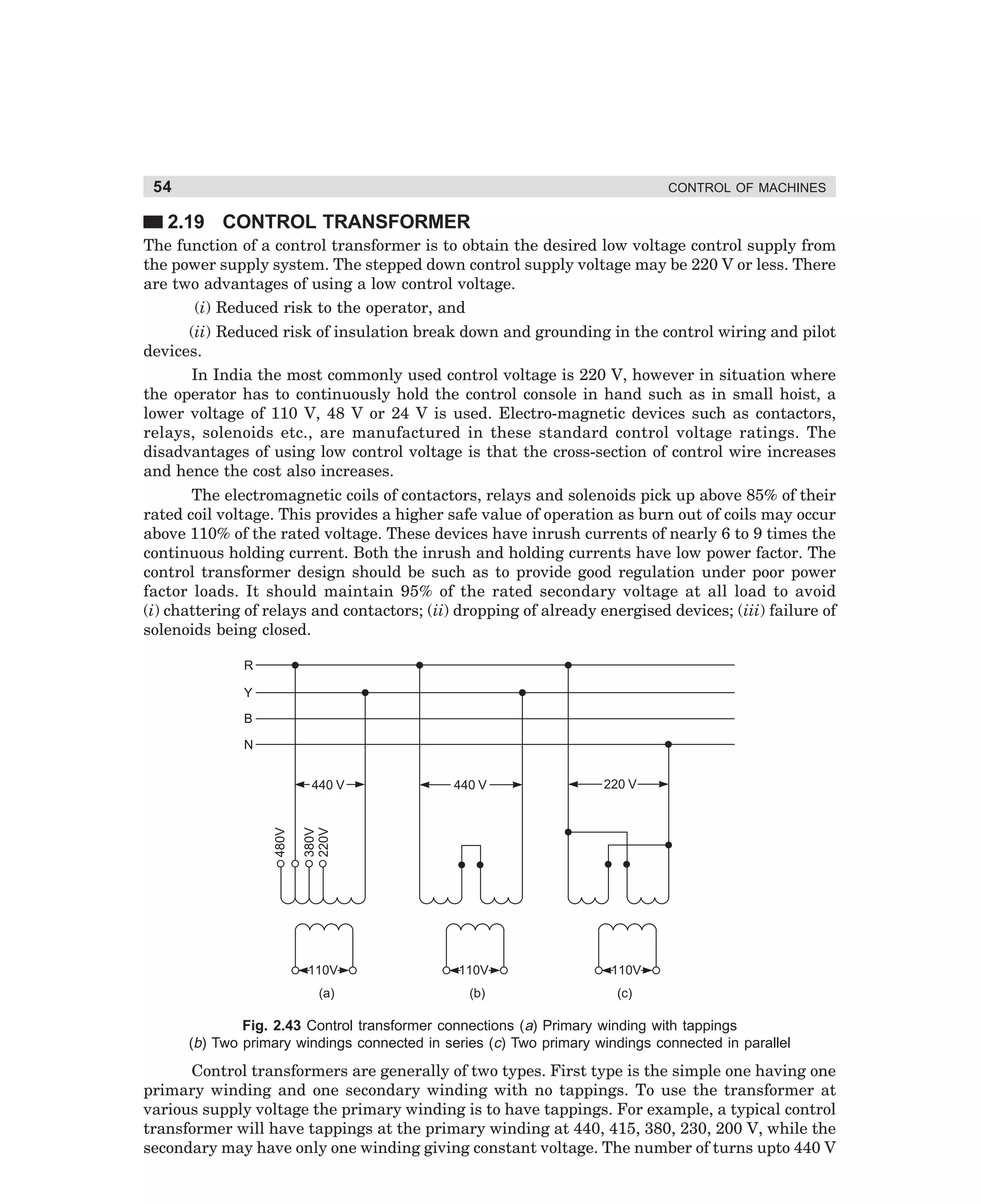
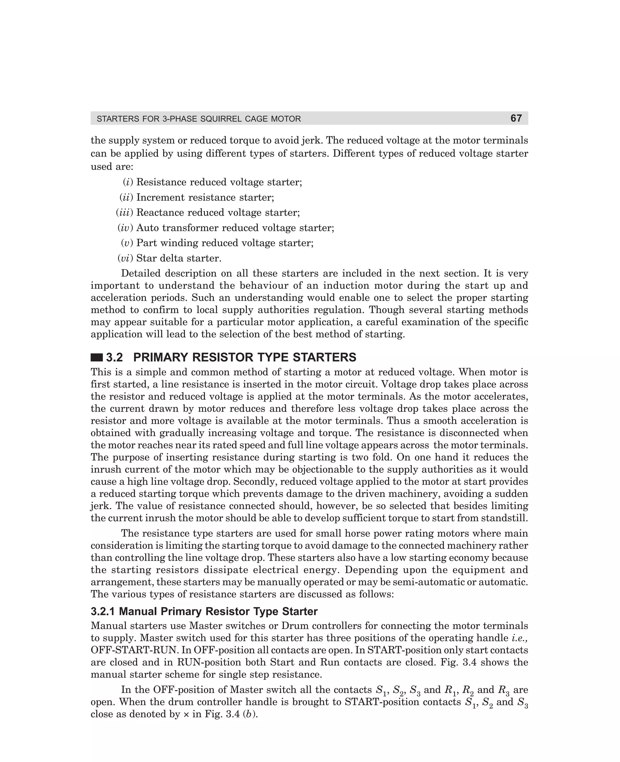
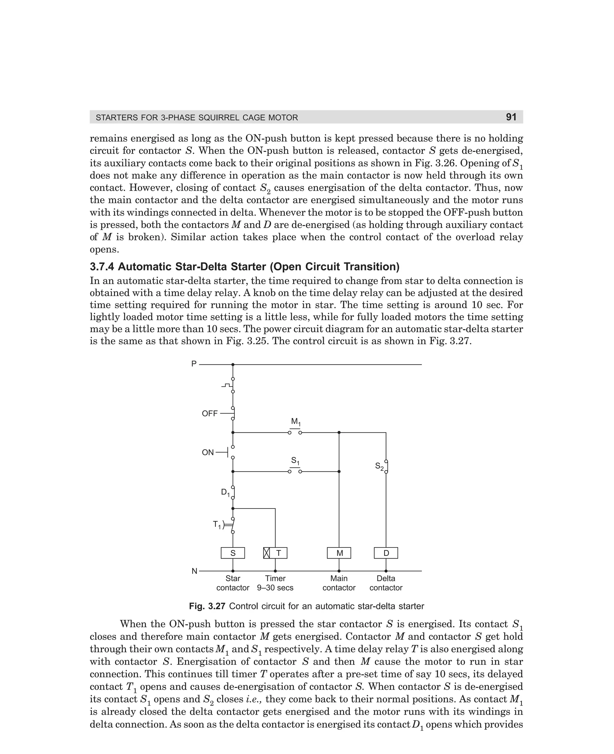
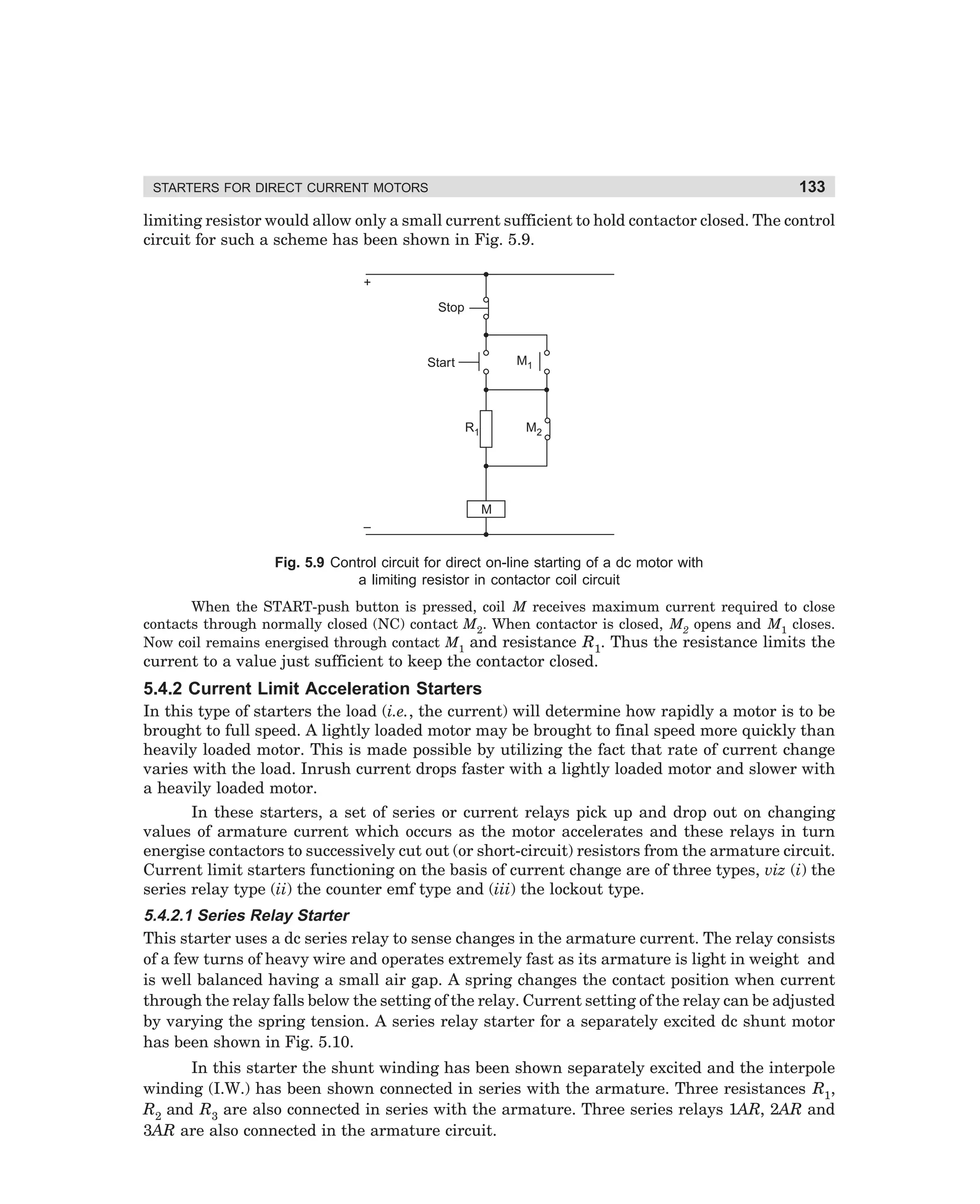
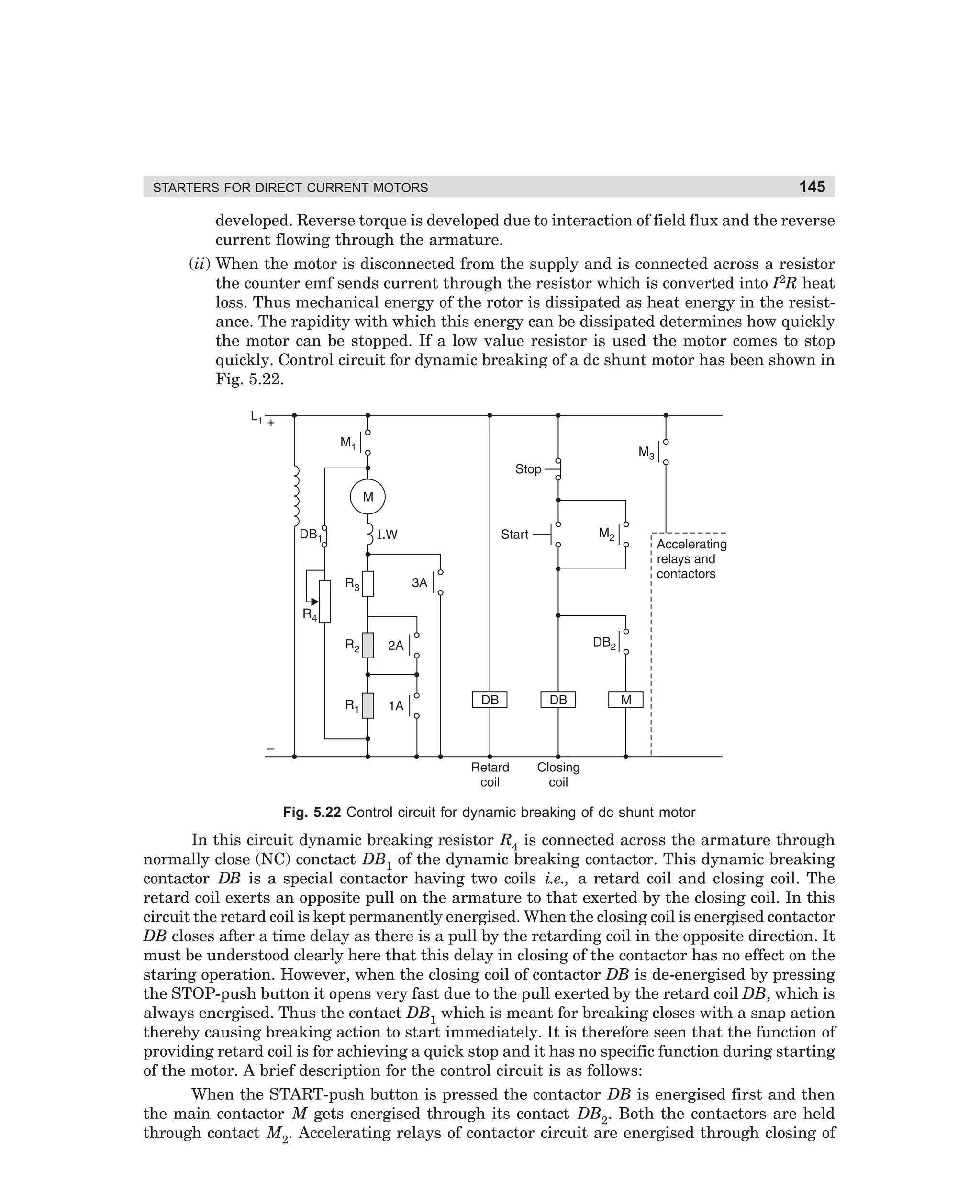
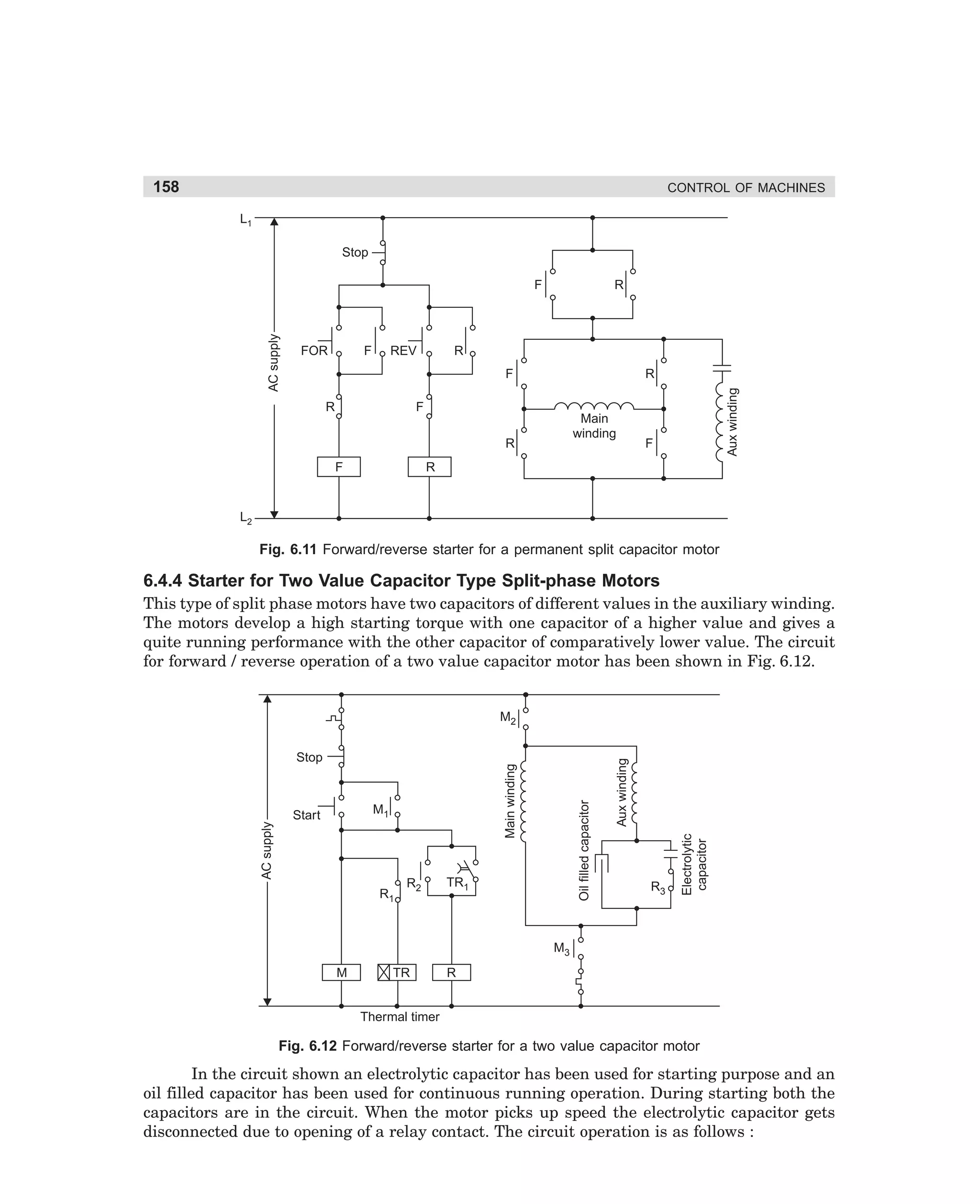
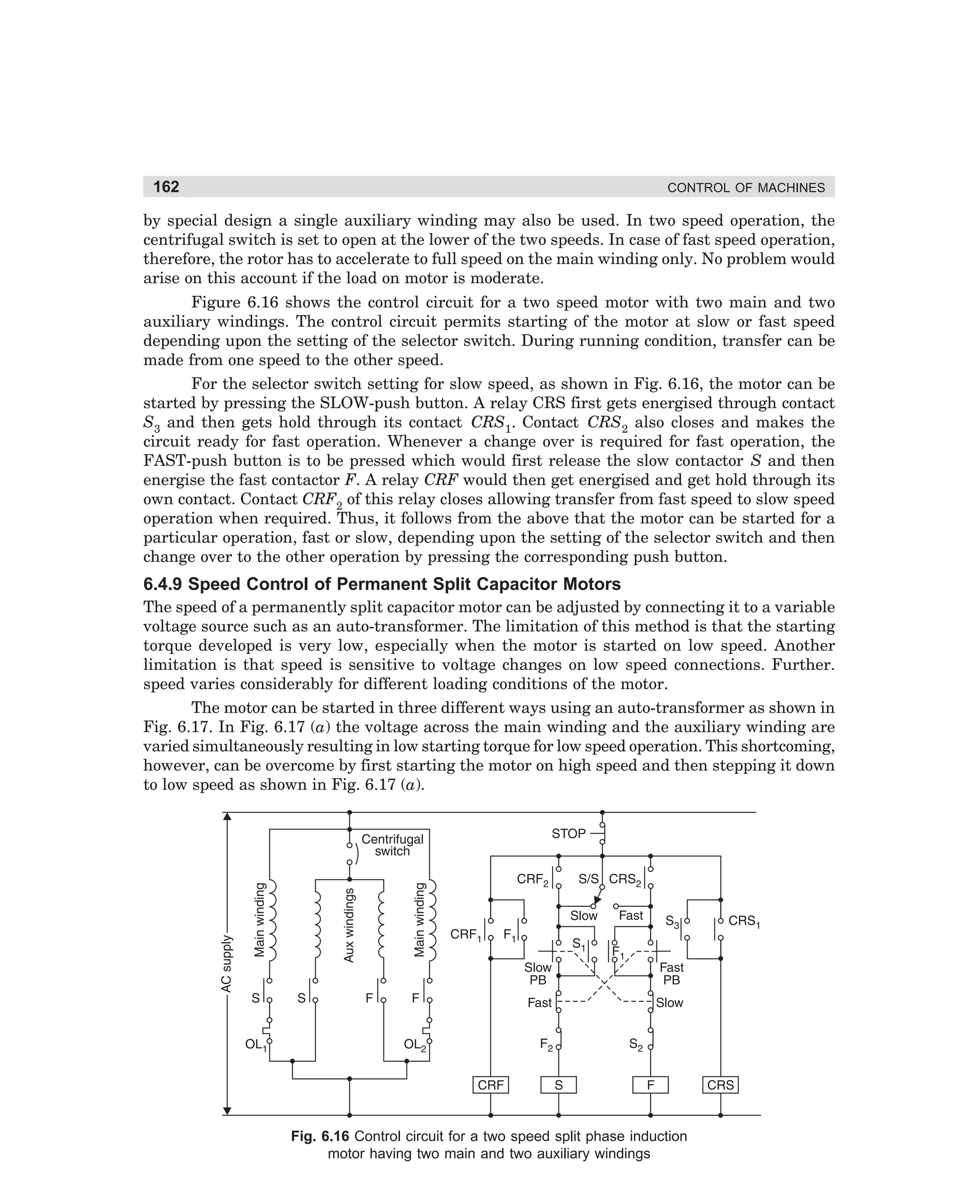
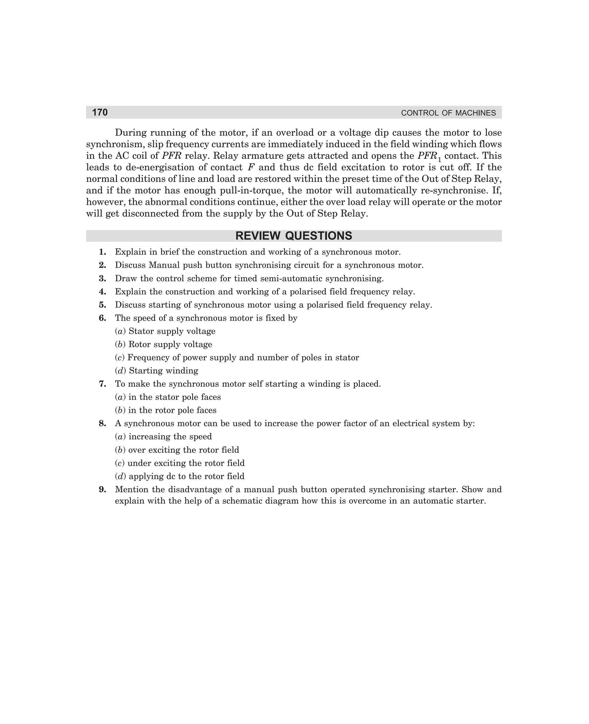
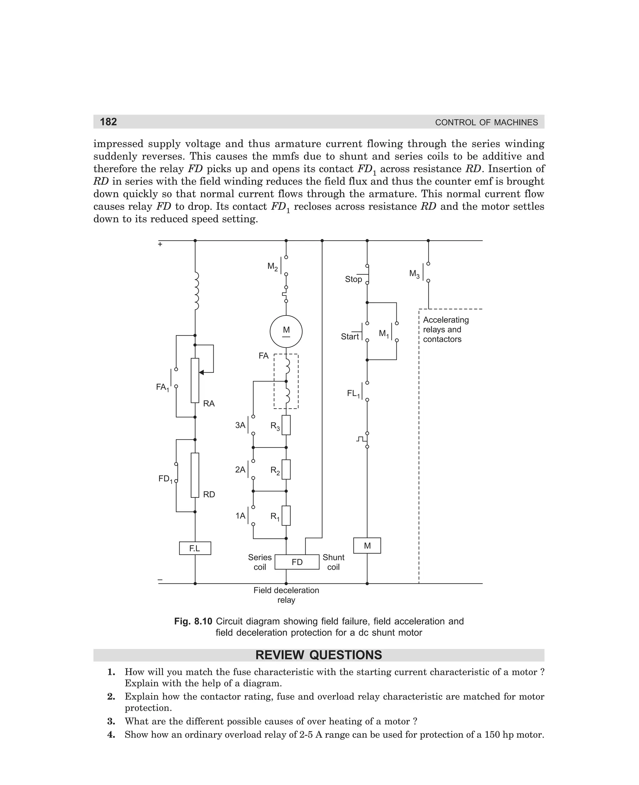
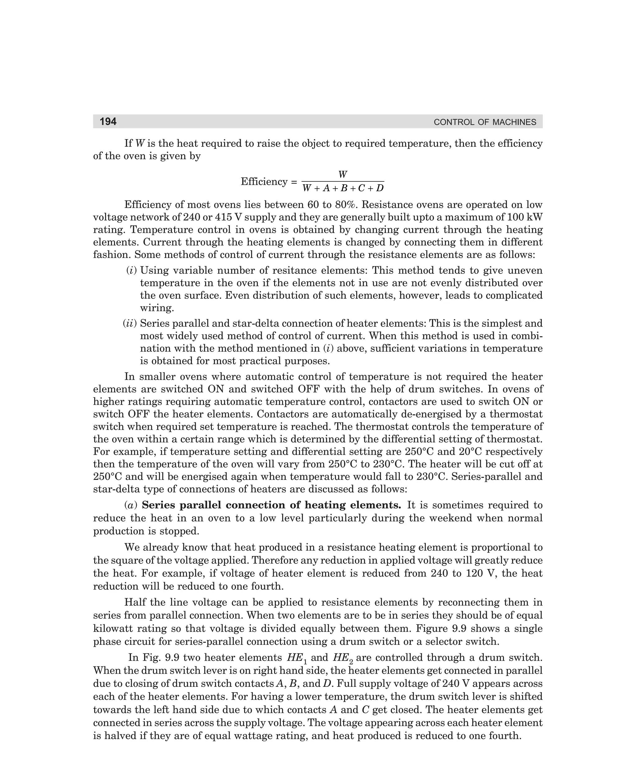
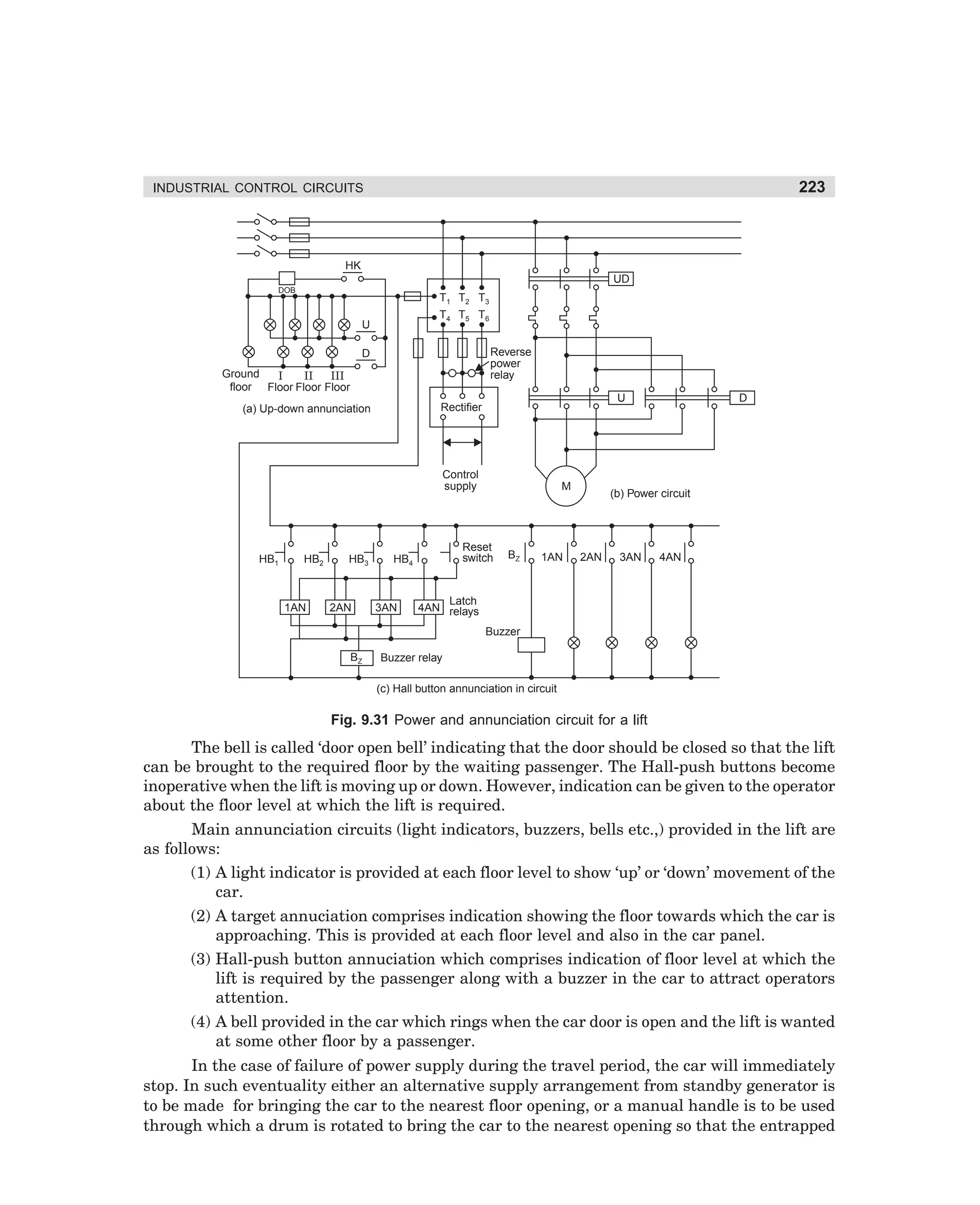
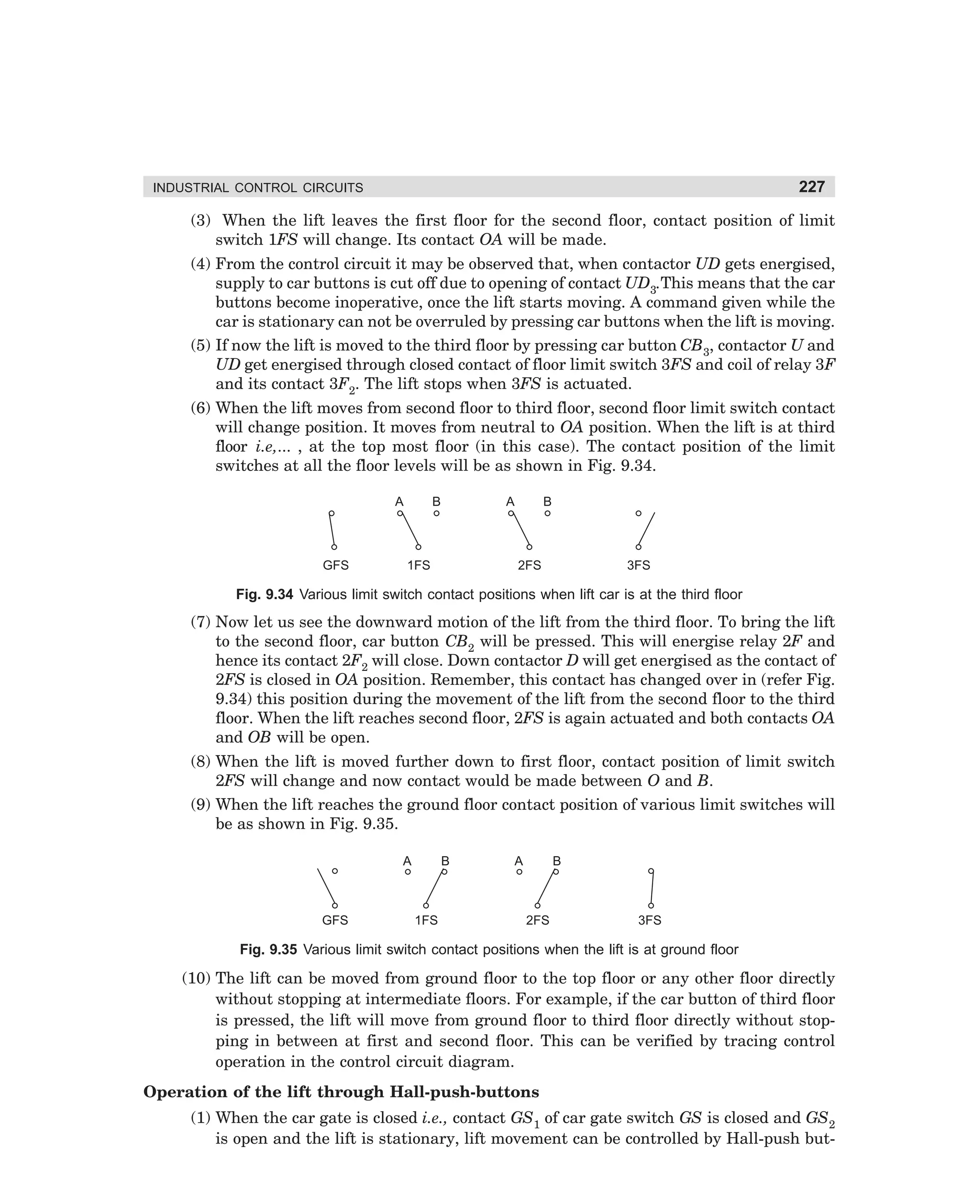
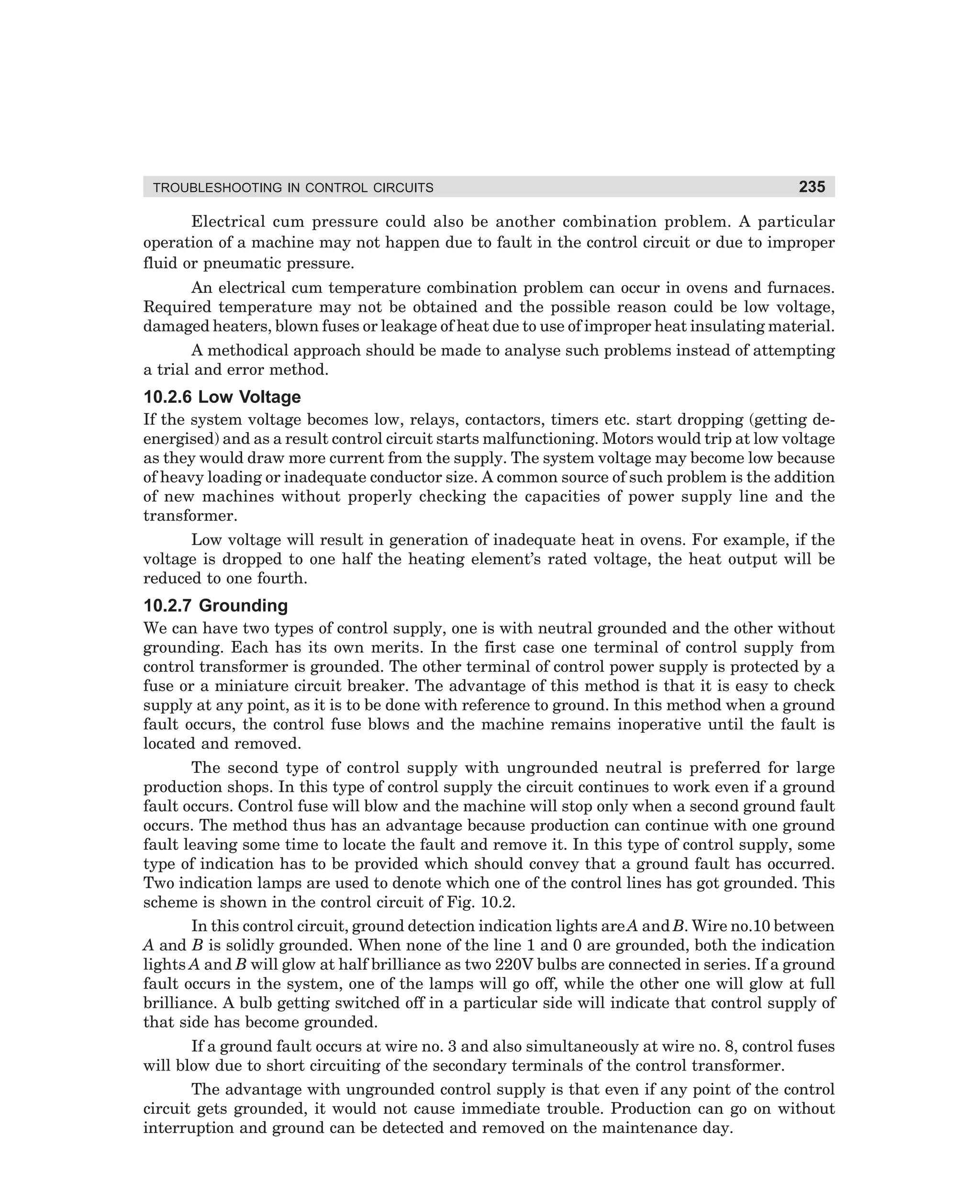
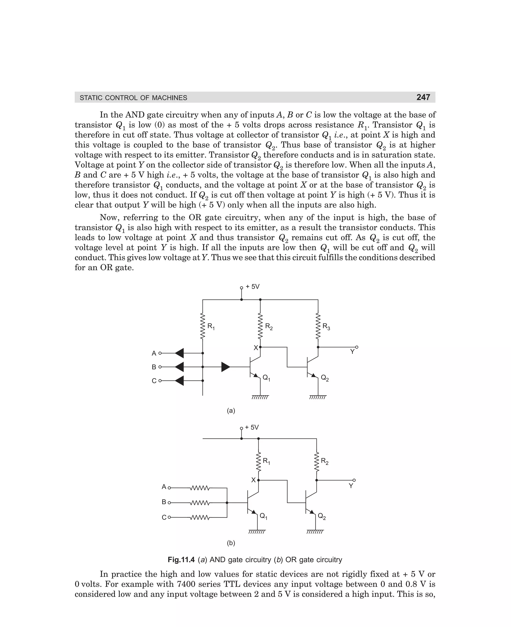
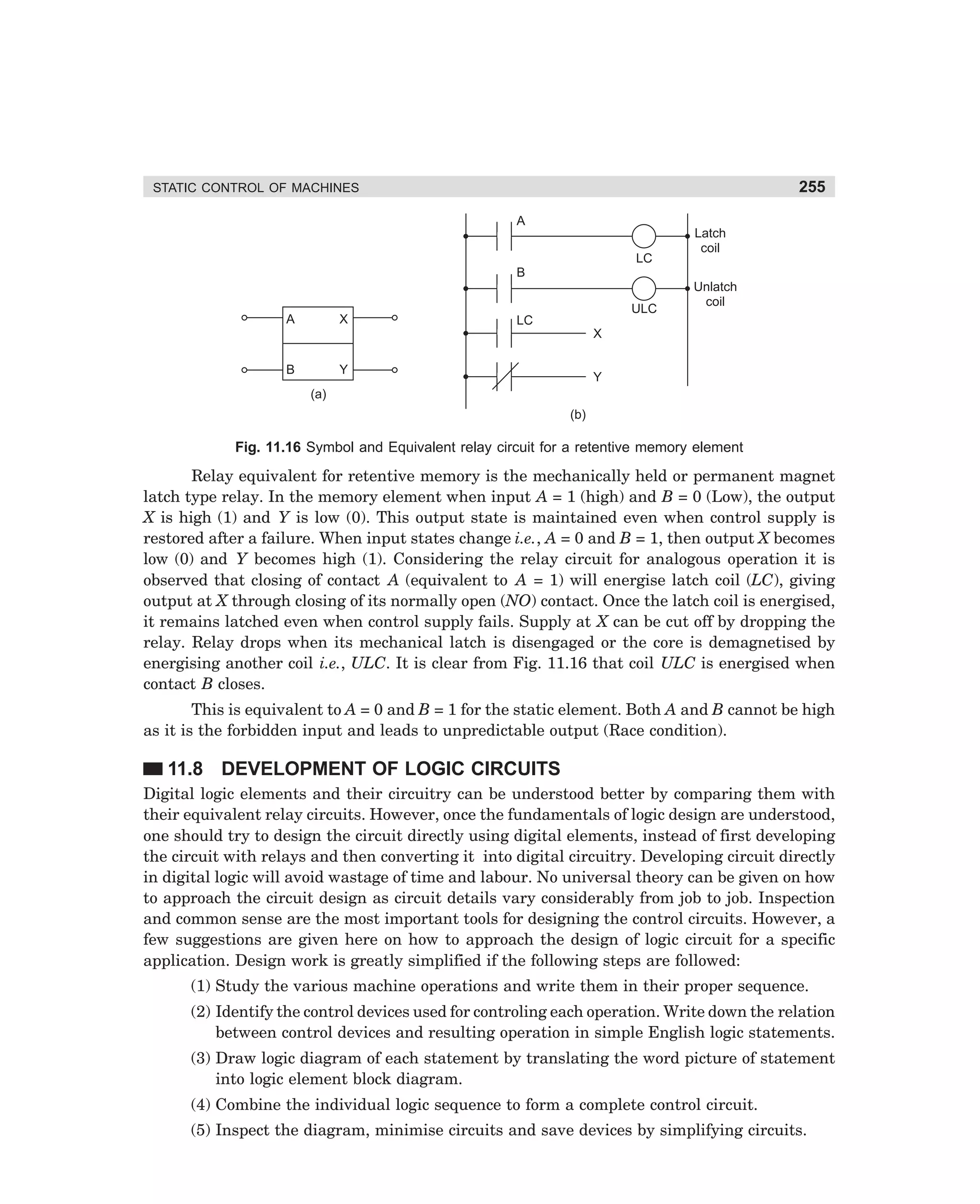
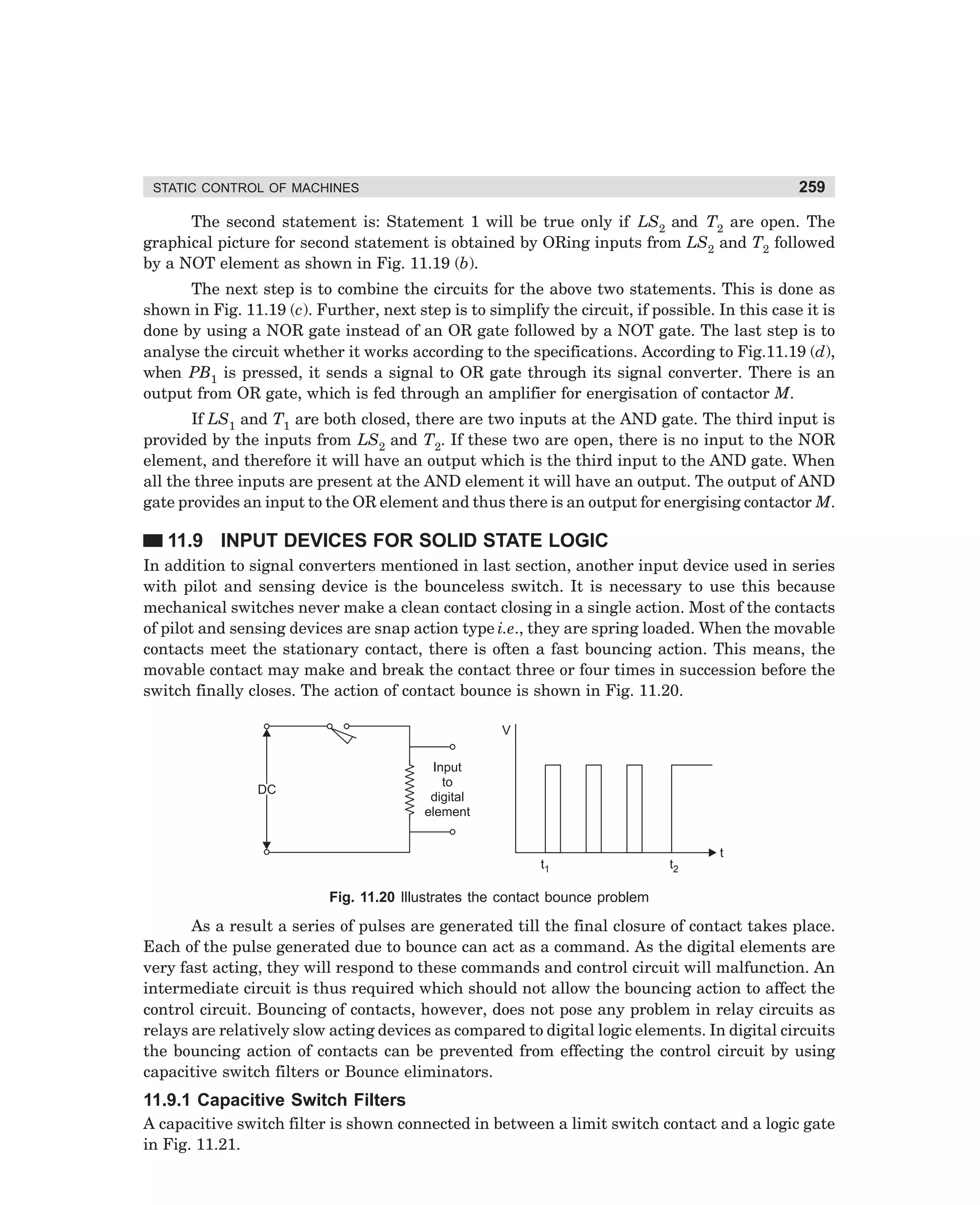
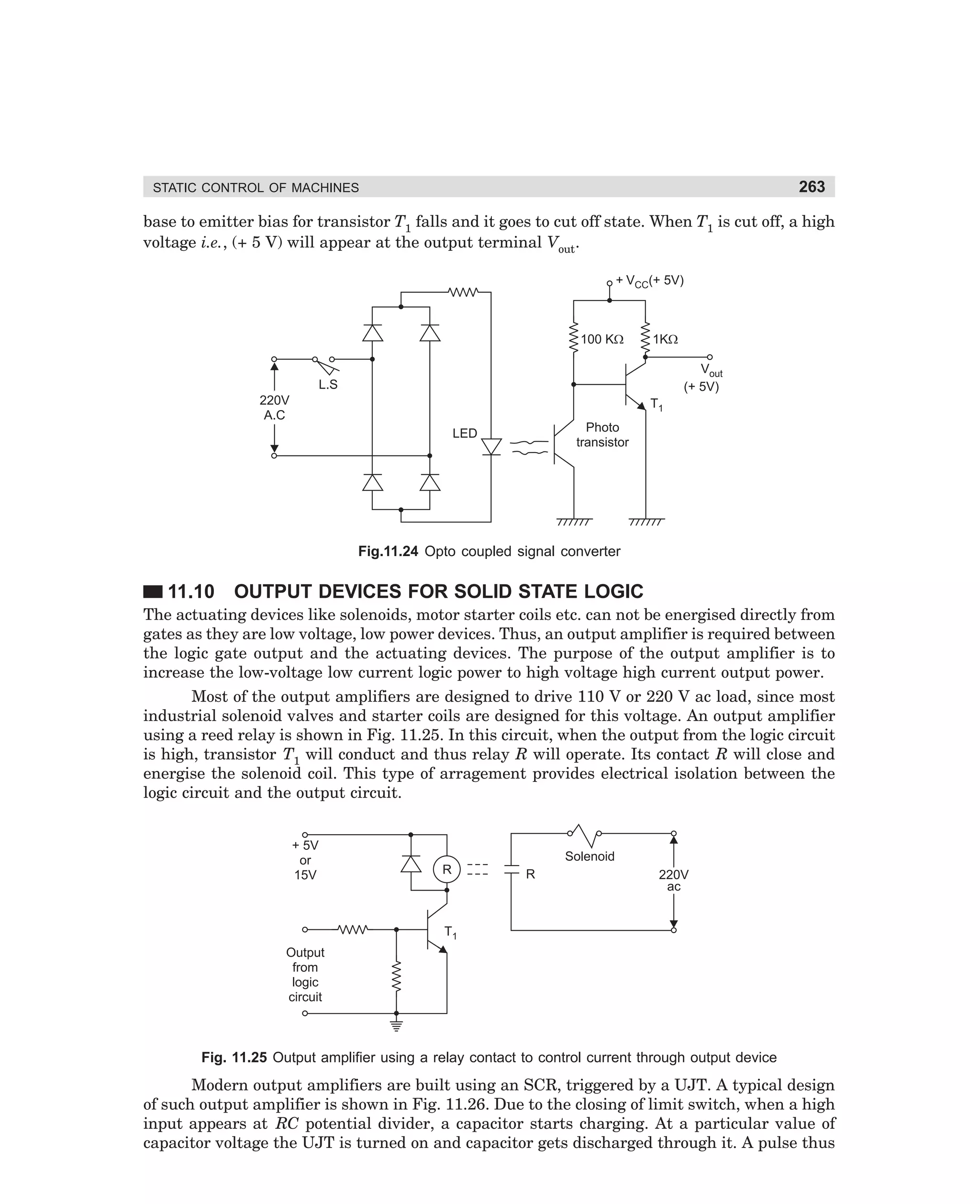
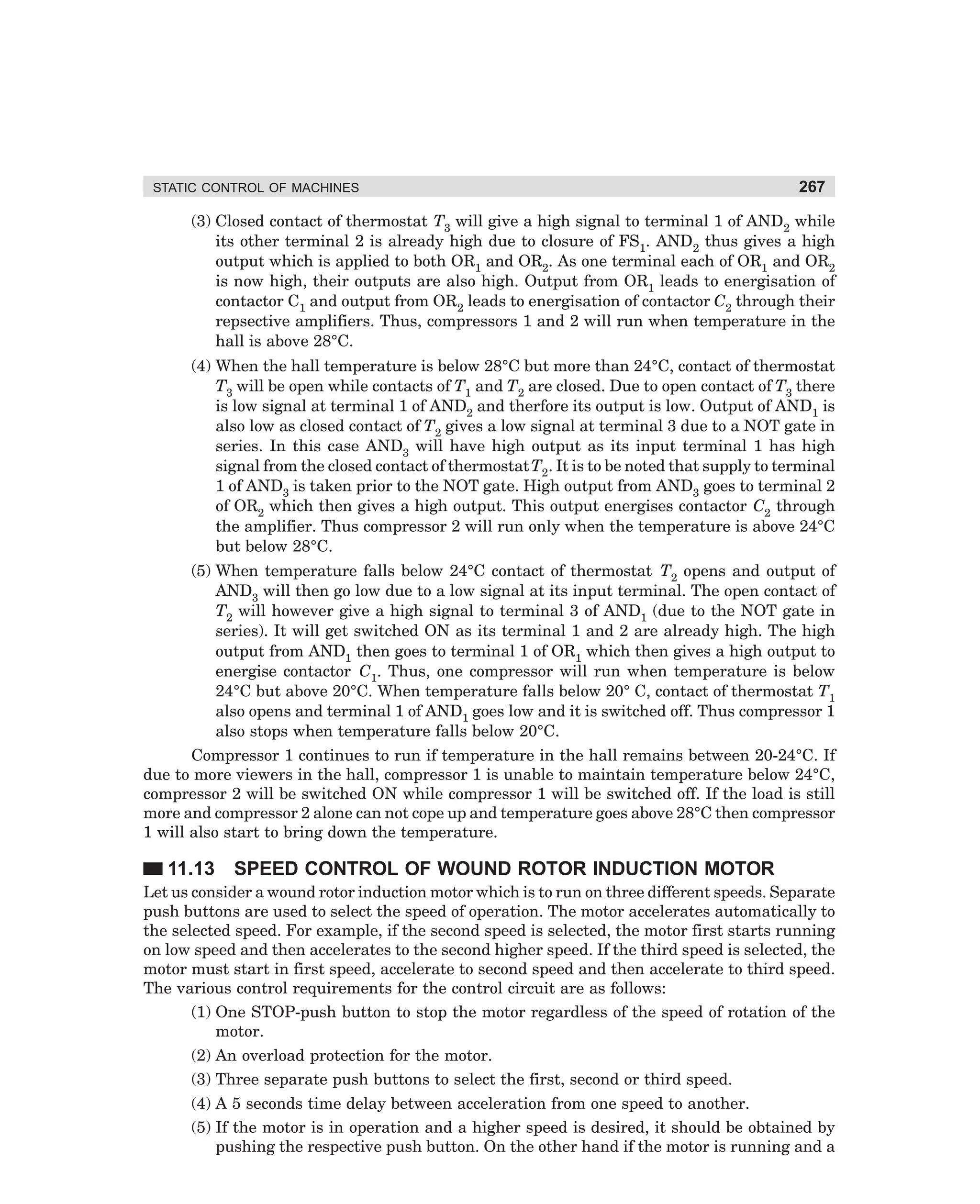
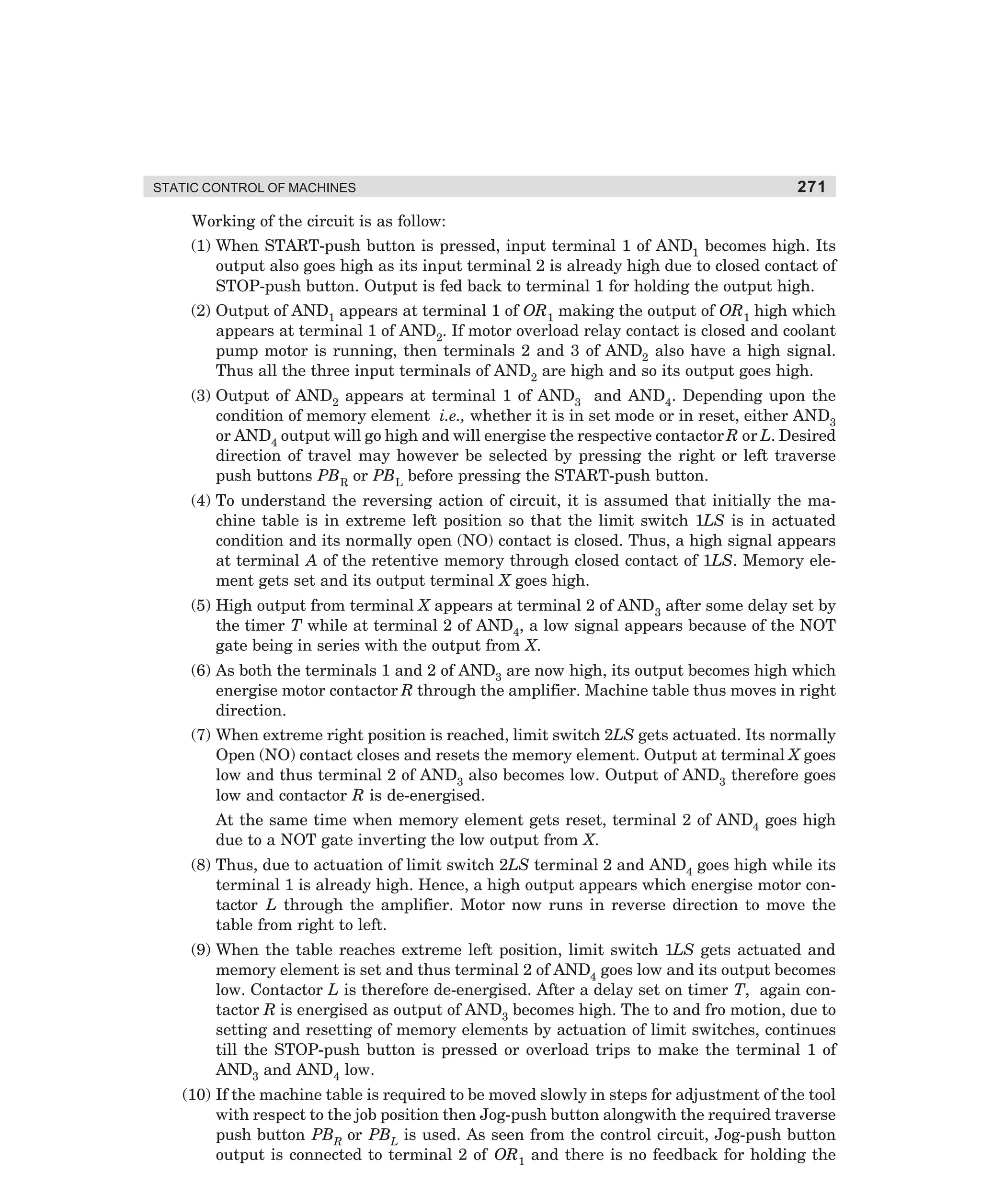
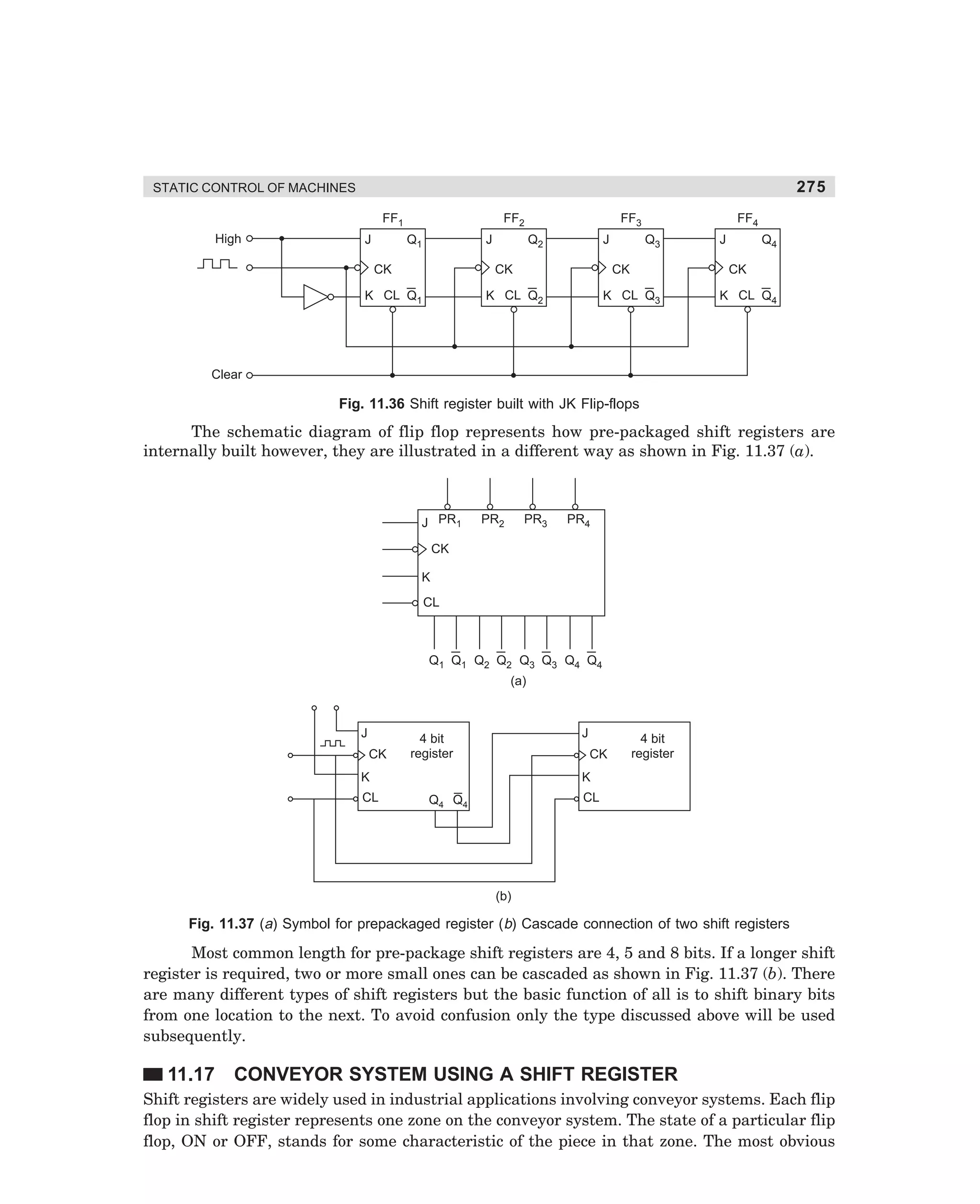
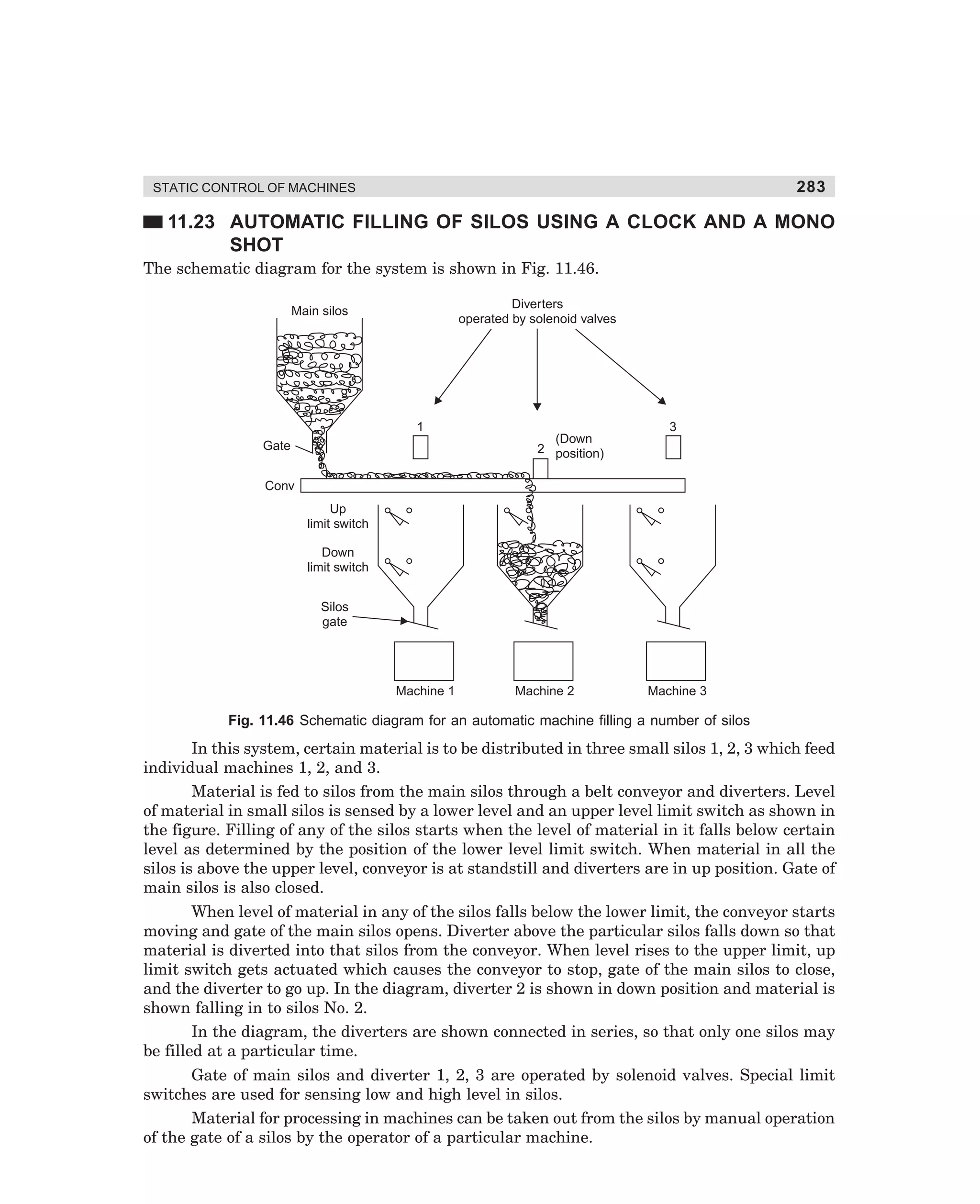
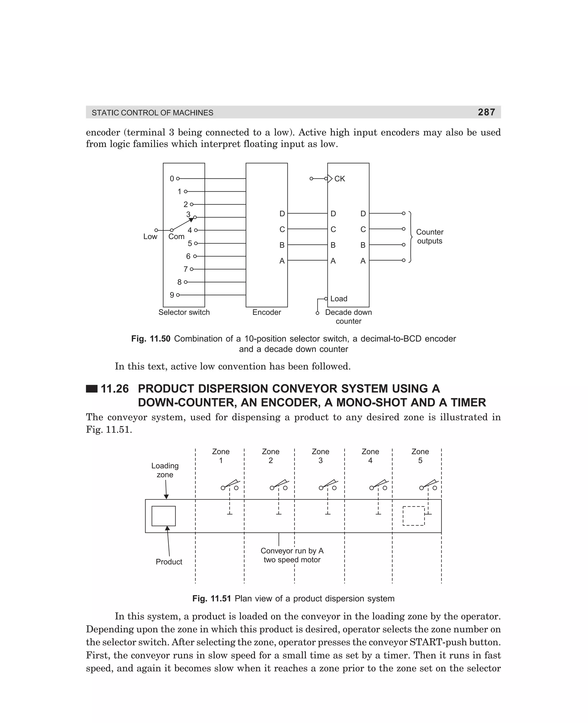
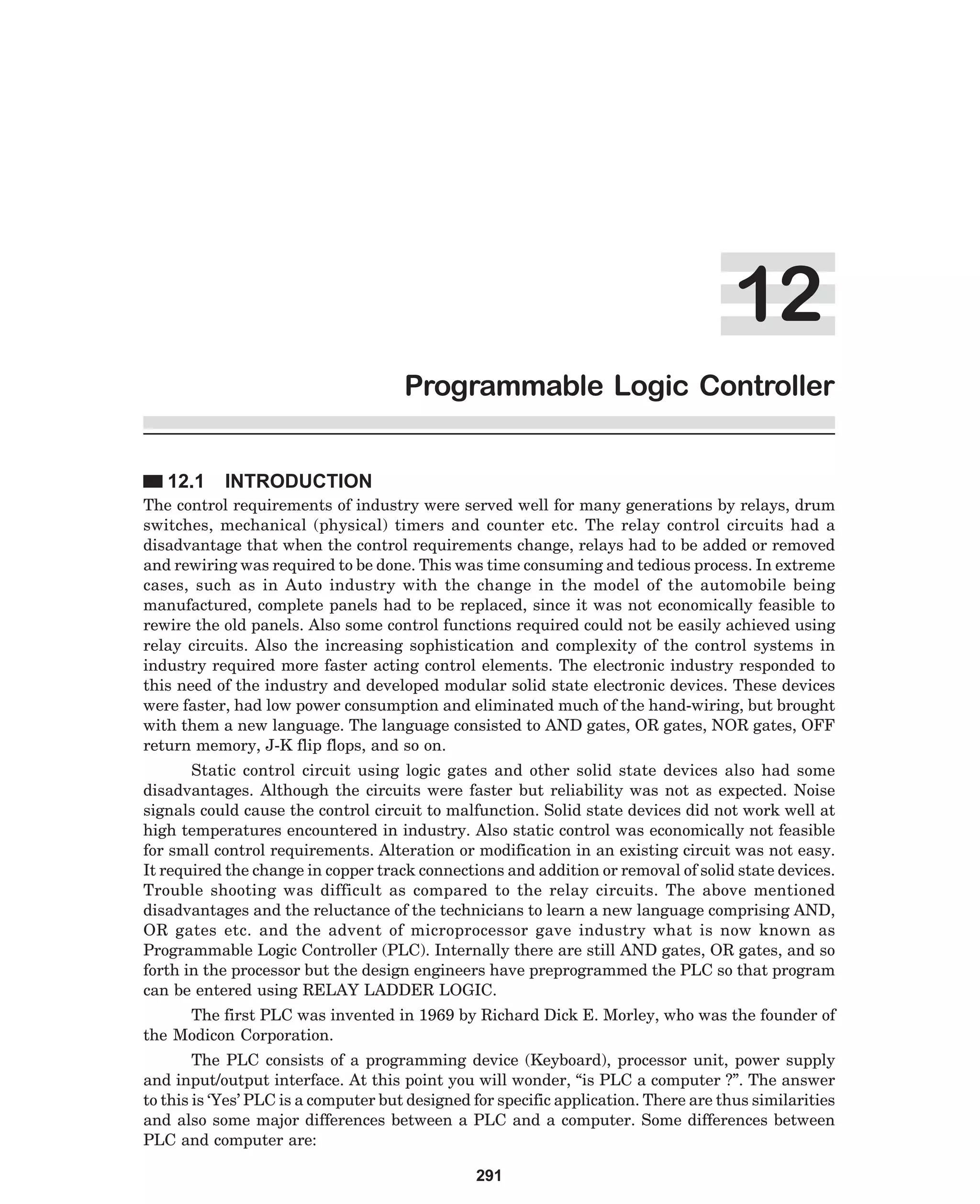
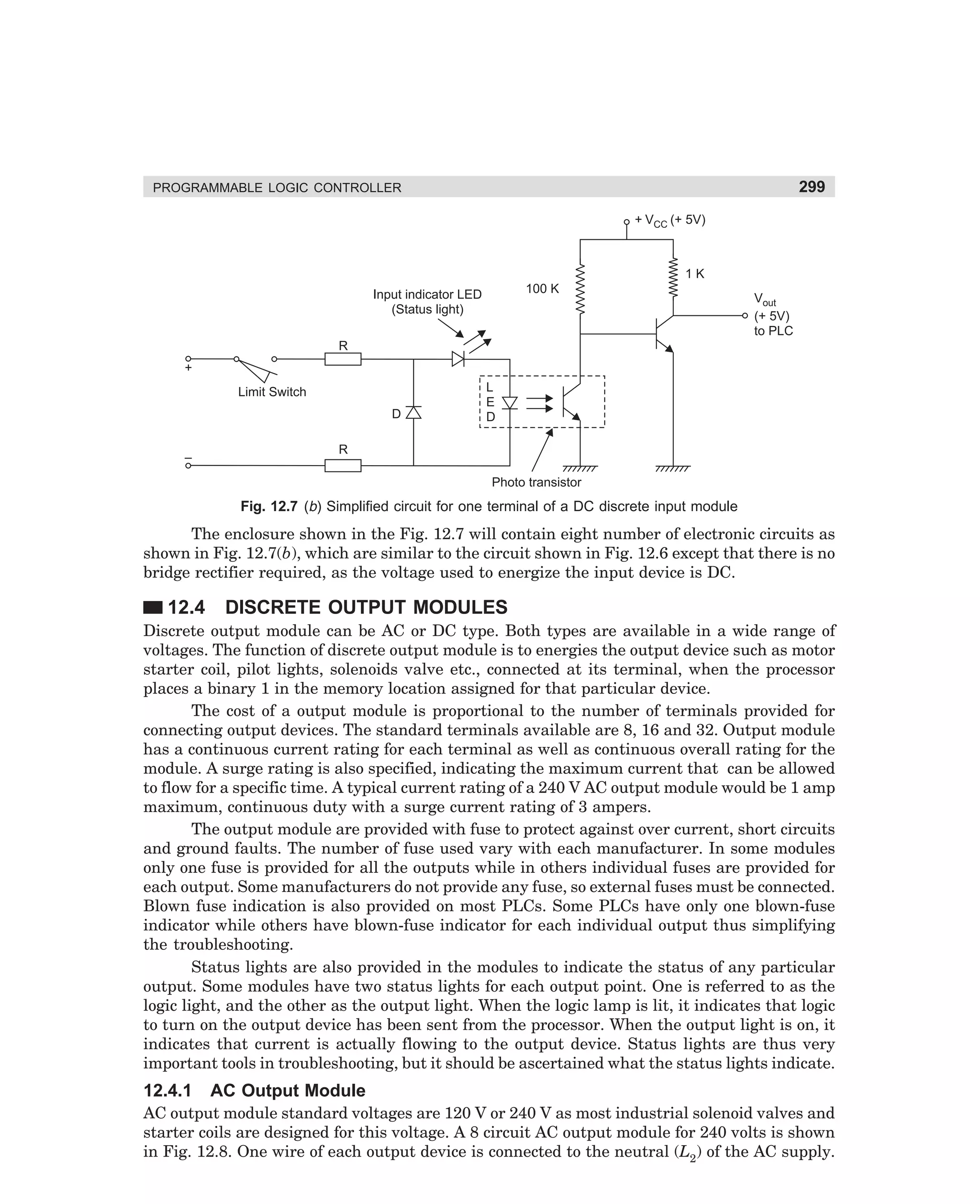
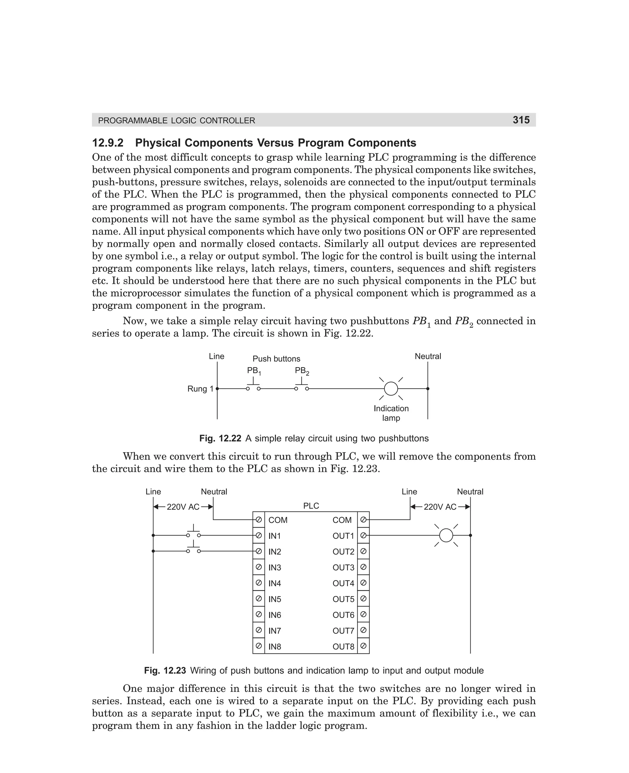
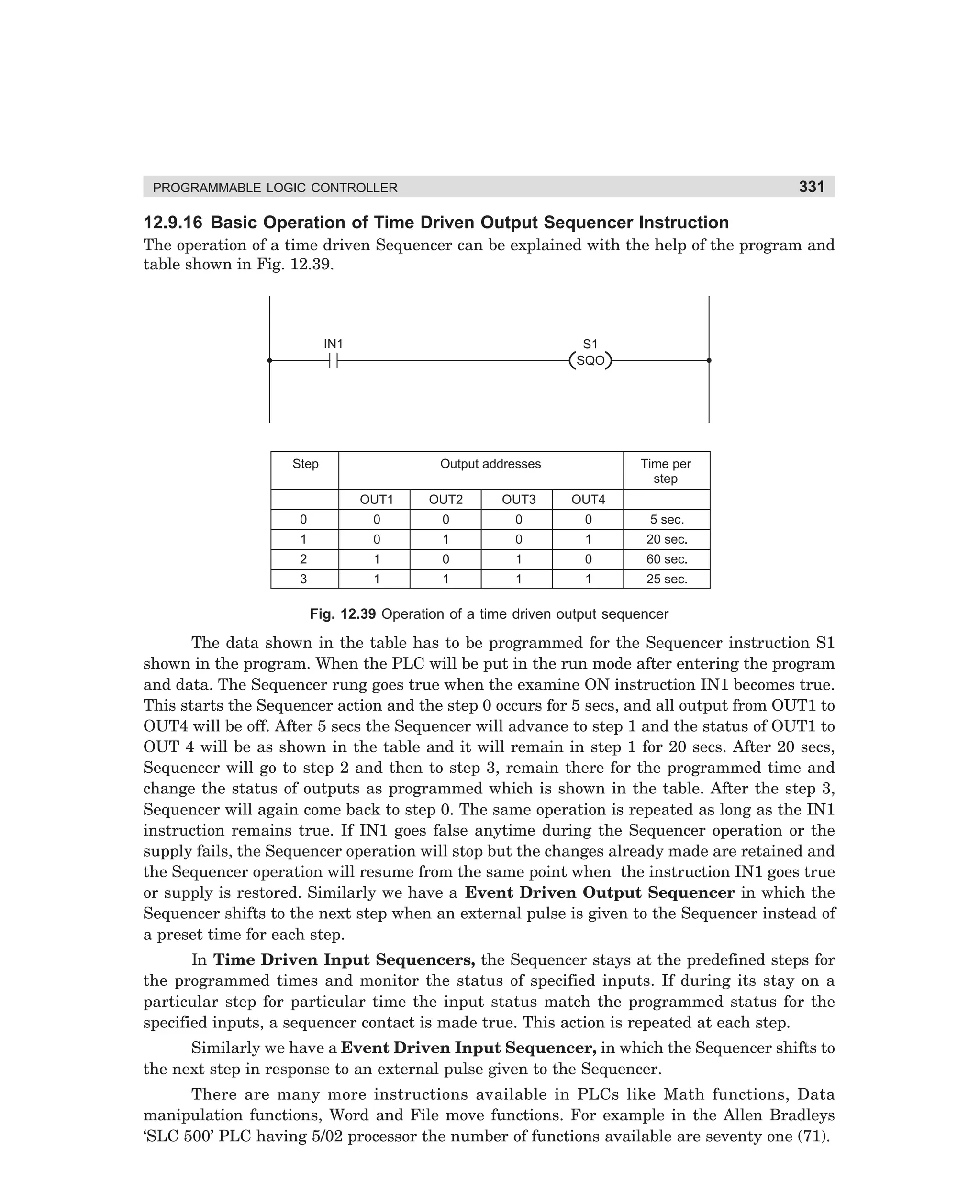
Fig. 3.29 Power circuit diagram for closed circuit transition type star-delta starter
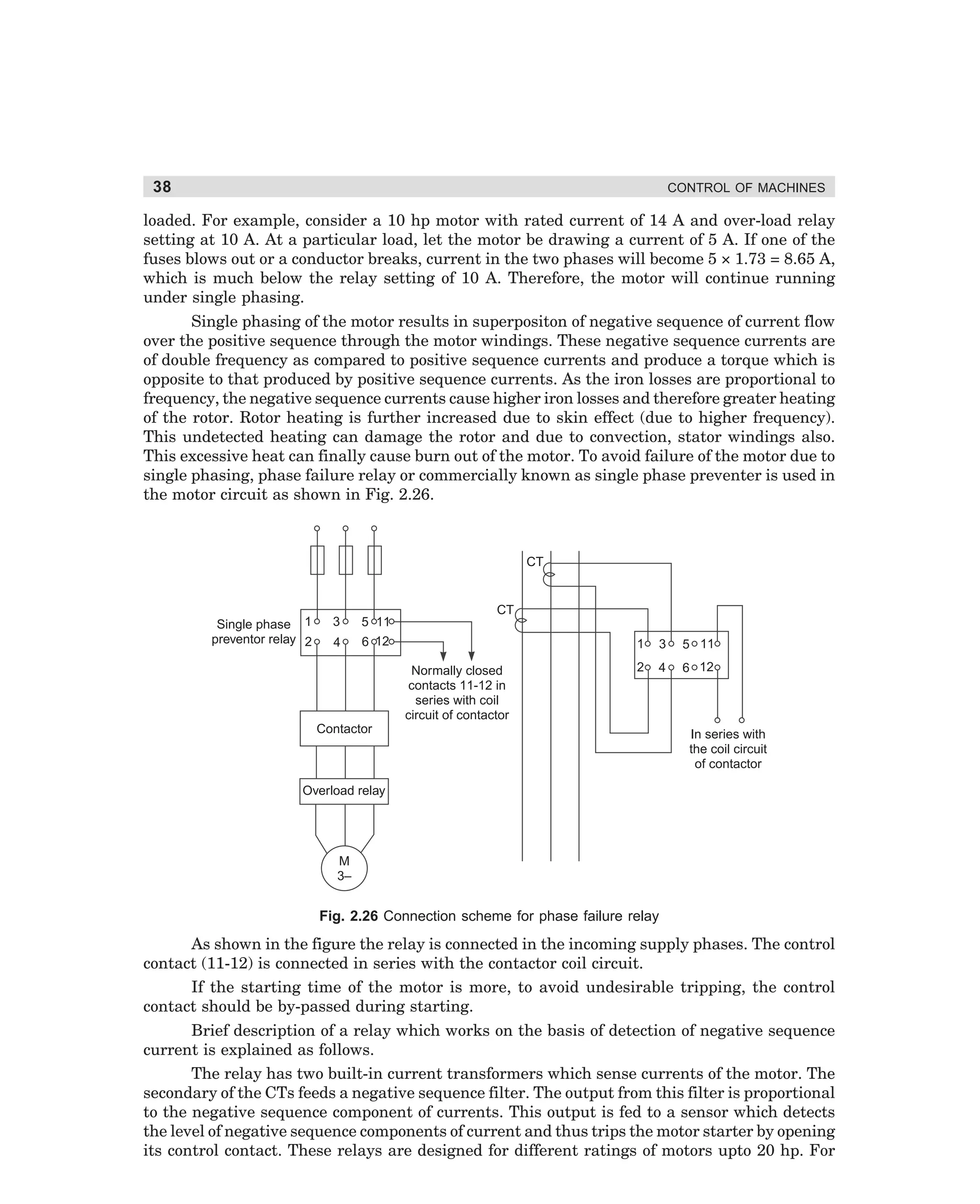
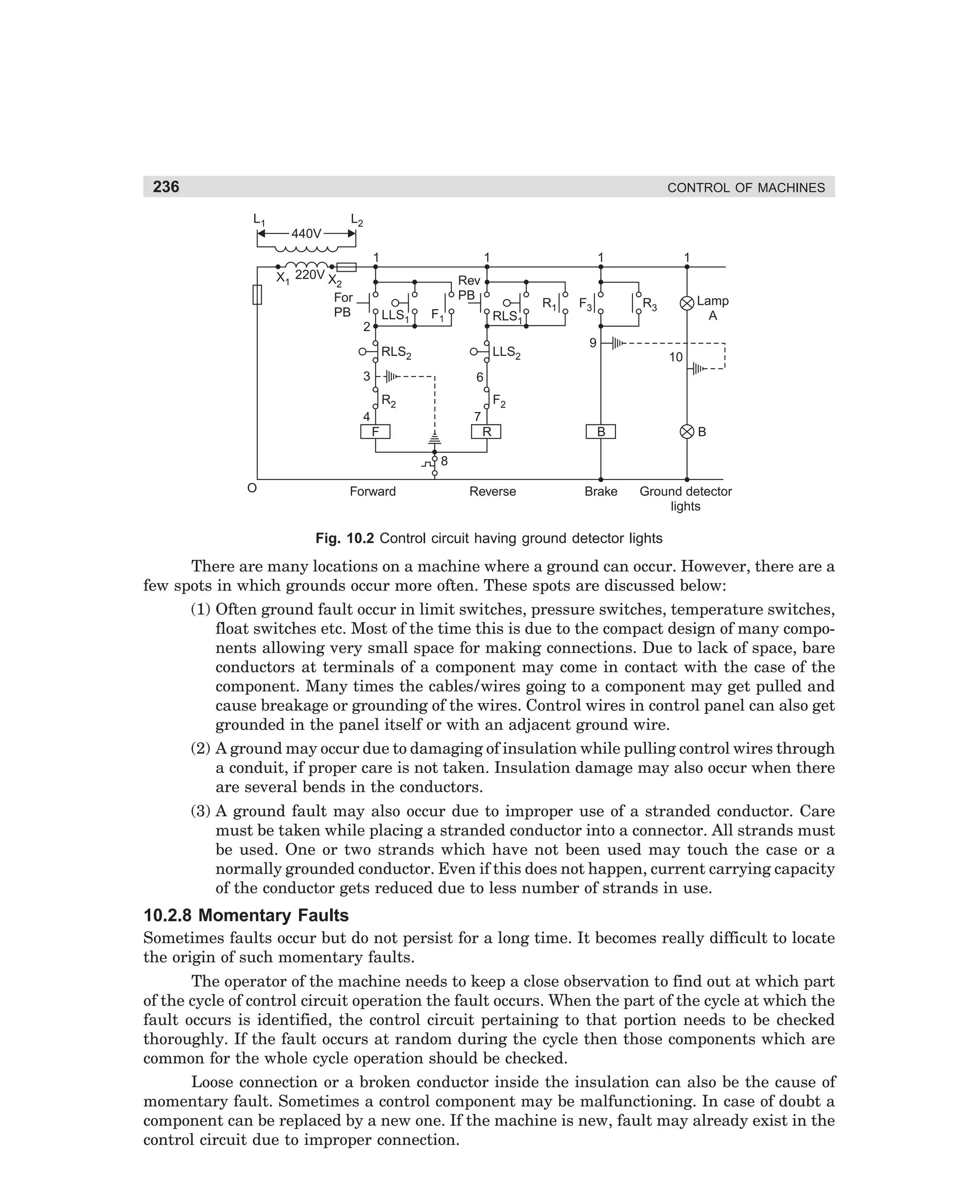
Contactor T connects a resistance in parallel with each of the windings. The motor continues
to run in star connection as contactor S is still closed. Connections due to contactor T is not
effective as value of resistances are very high. After a little more delay, contactor S is deenergised. With de-energisation of contactor S, contactor D closes. During the small time gap
between opening of contactor S and closing of contactor D the windings remain connected to
supply (through contactor T ) in delta connection with resistances in series. After the closure
of contactor D the contactor T becomes open with some time delay. It may be noted that just at
the instant of closing of contactor D, the windings get connected in delta as the contactor D
gets connected in parallel with contactor T and thus by-pass its action. The operating sequence
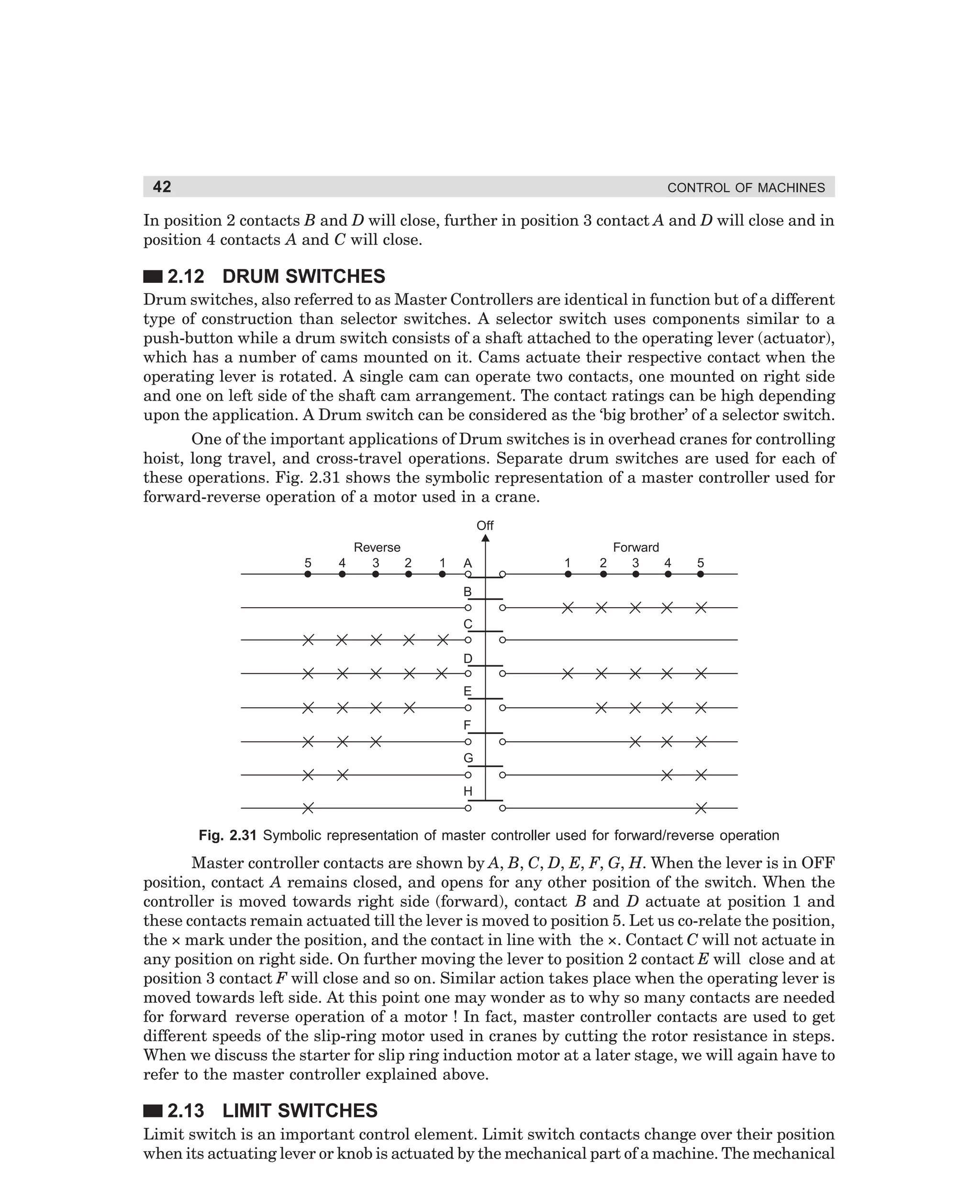
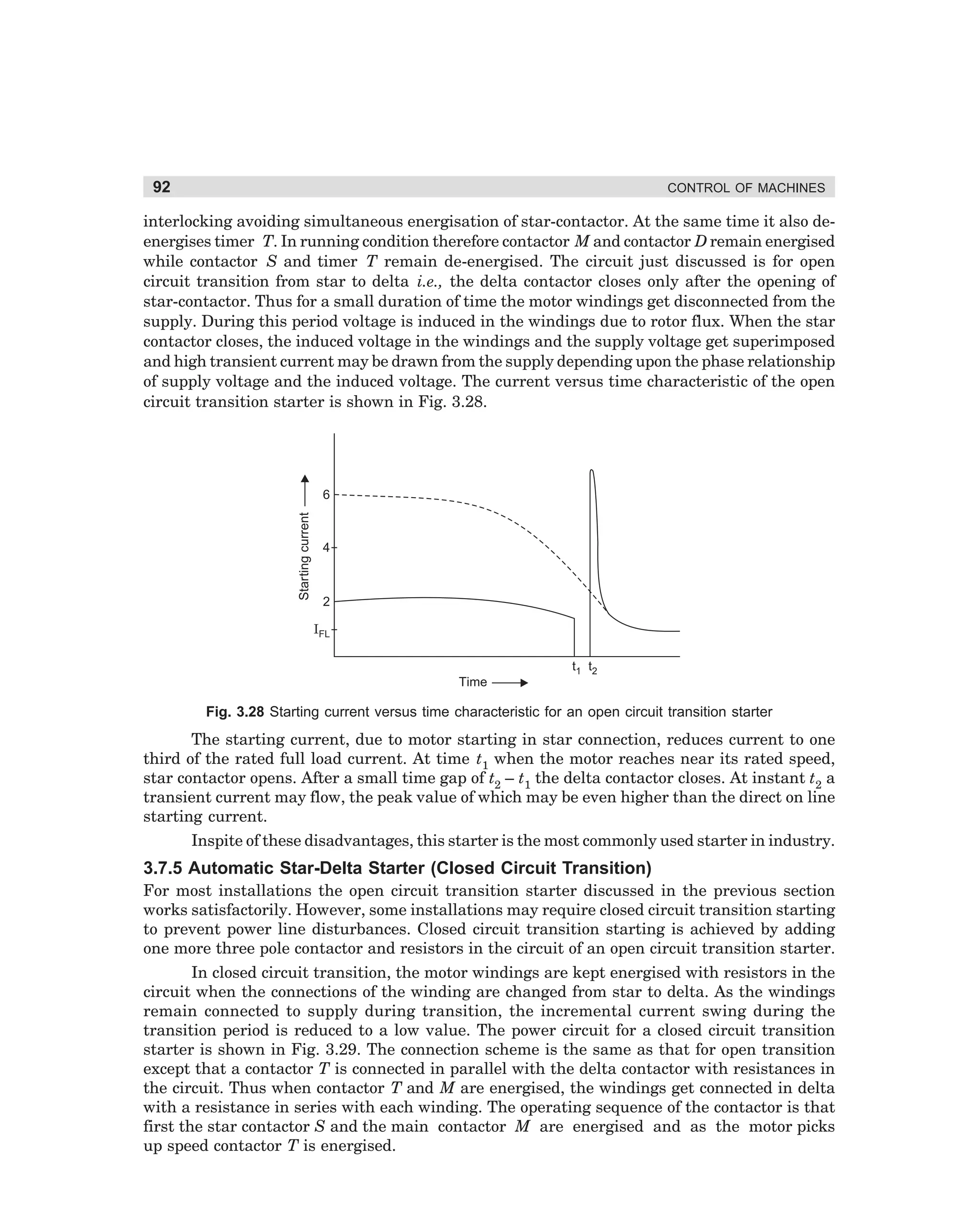
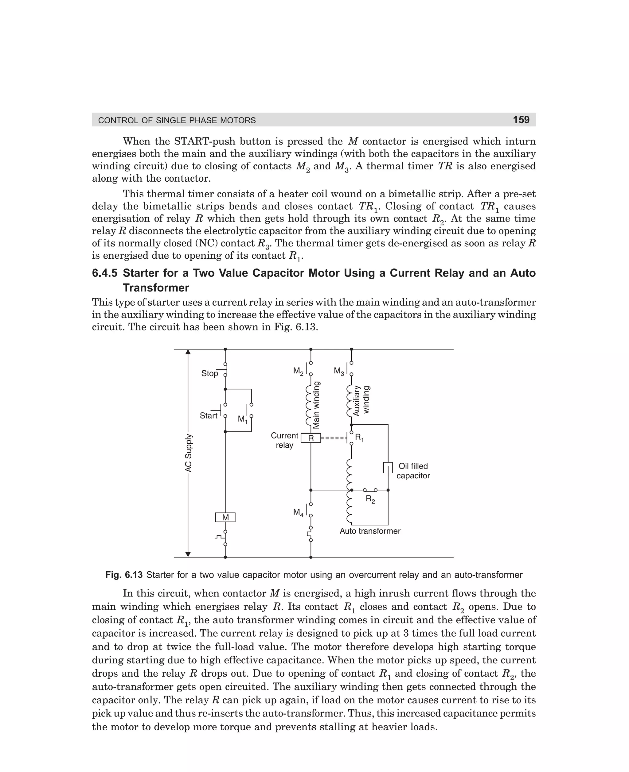
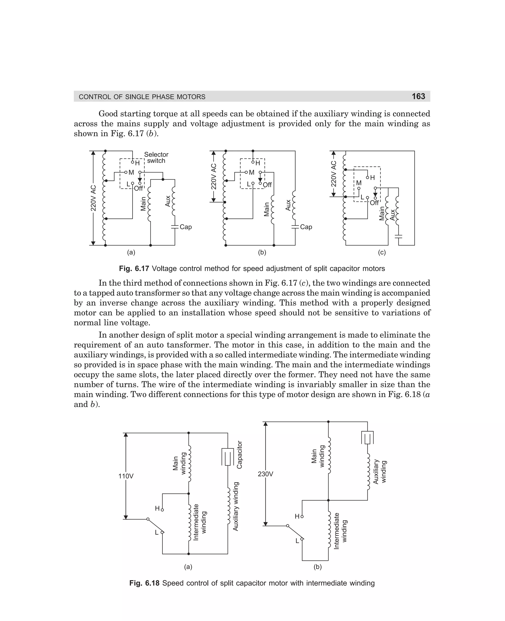
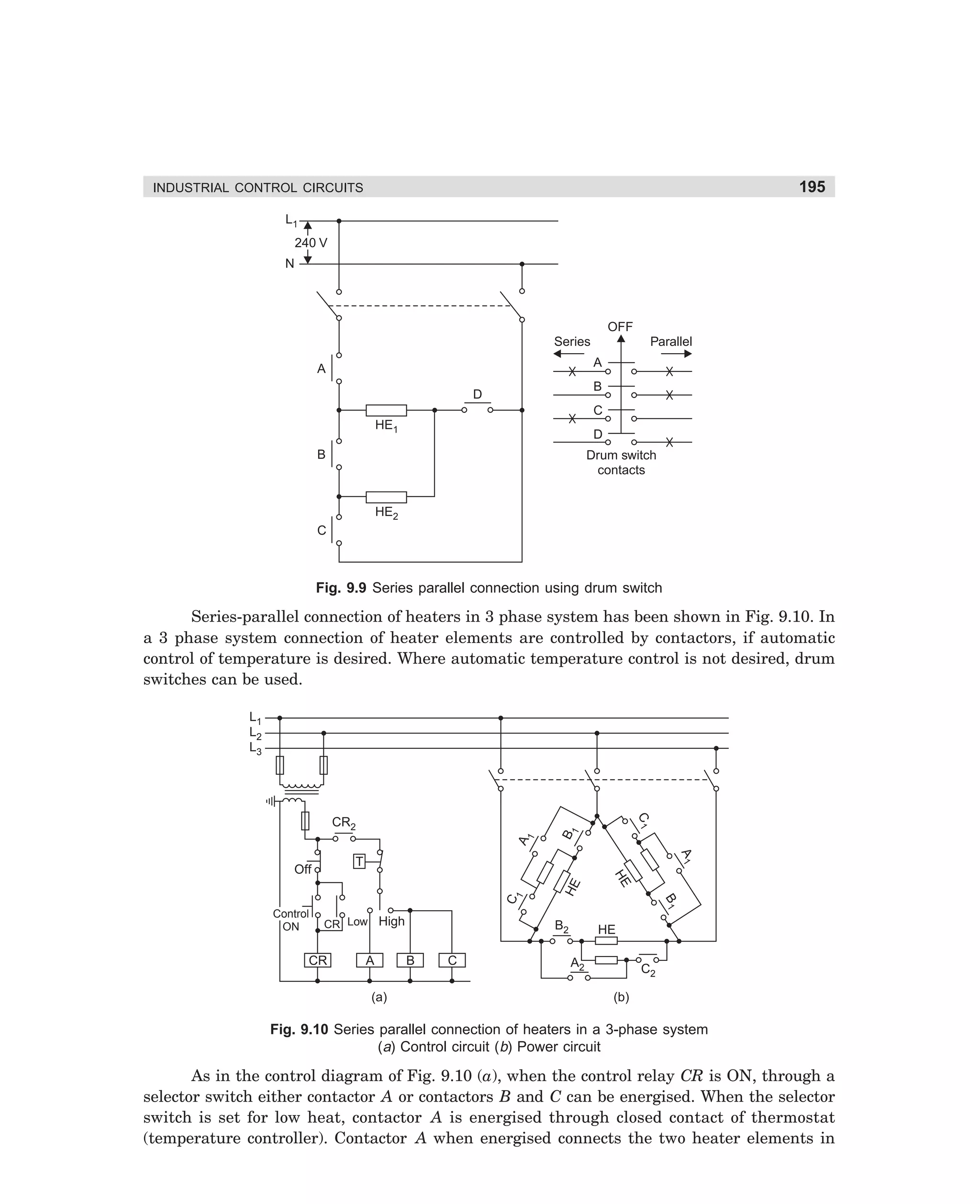
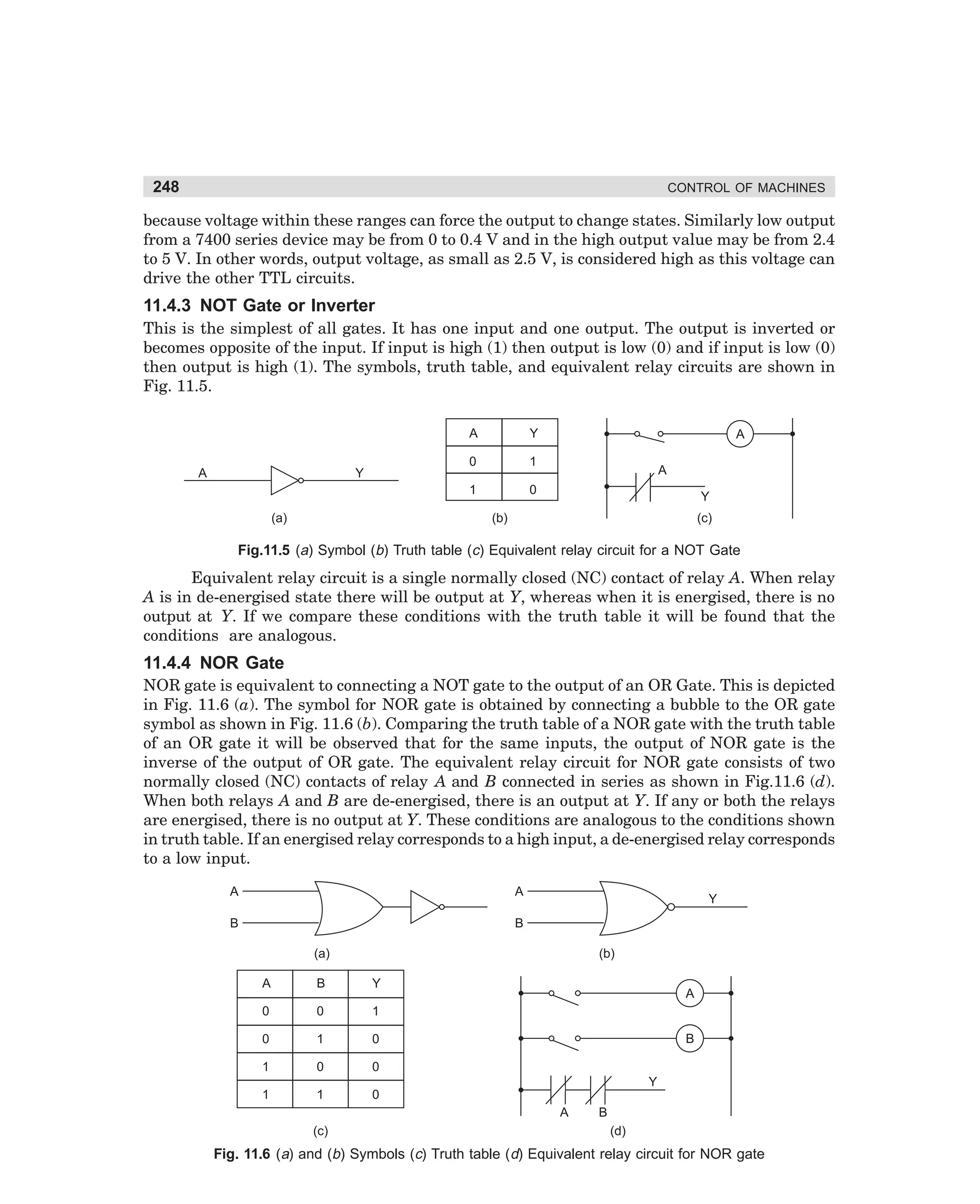
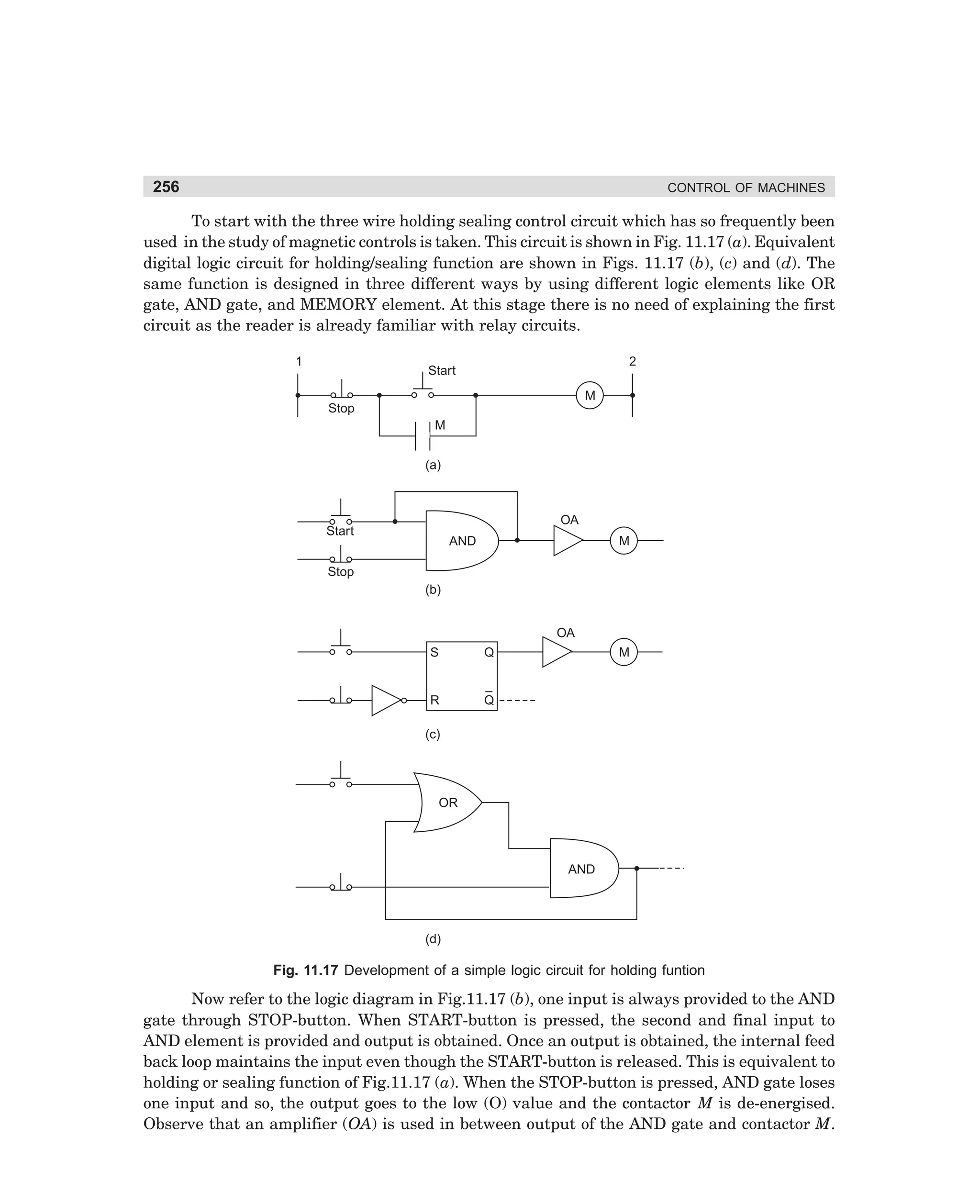
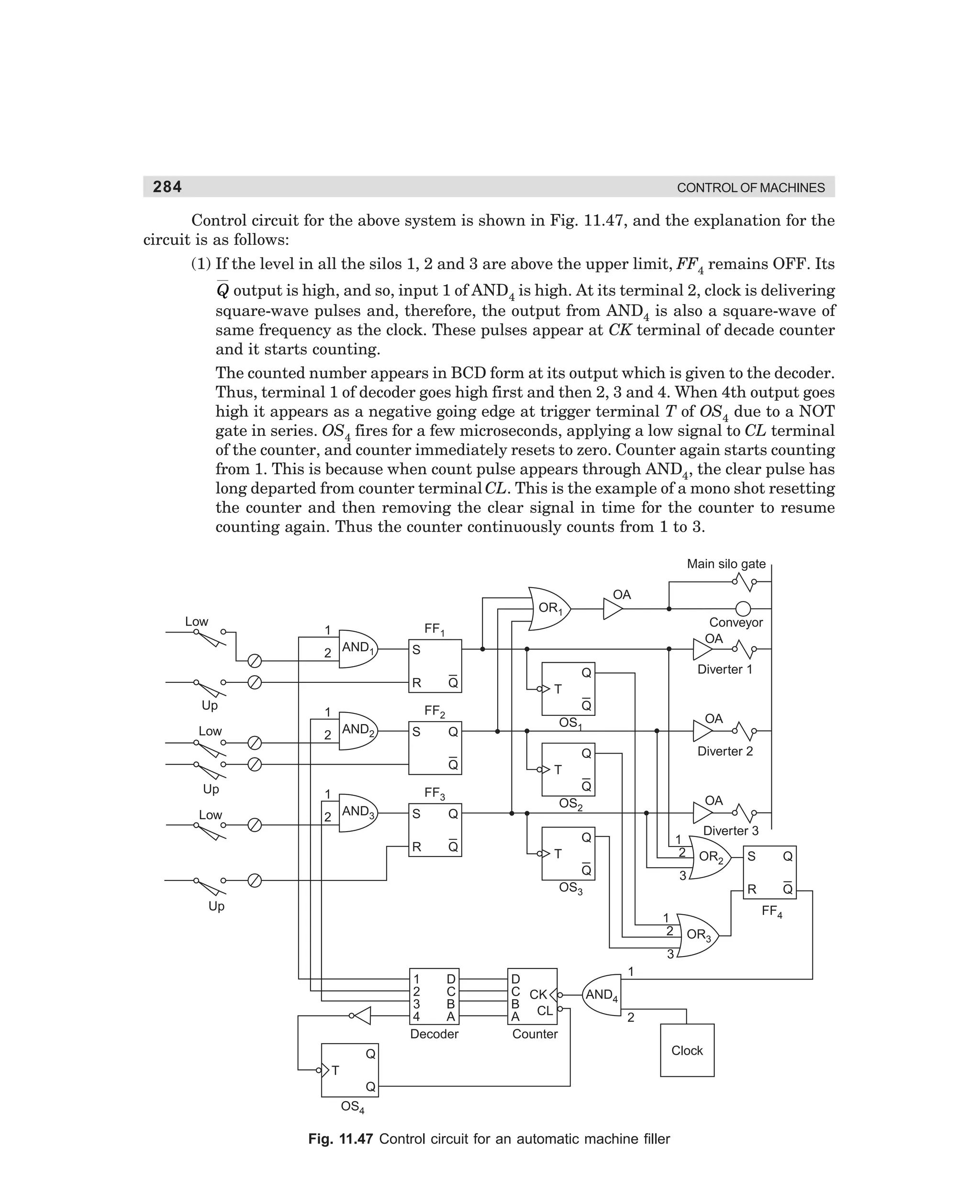
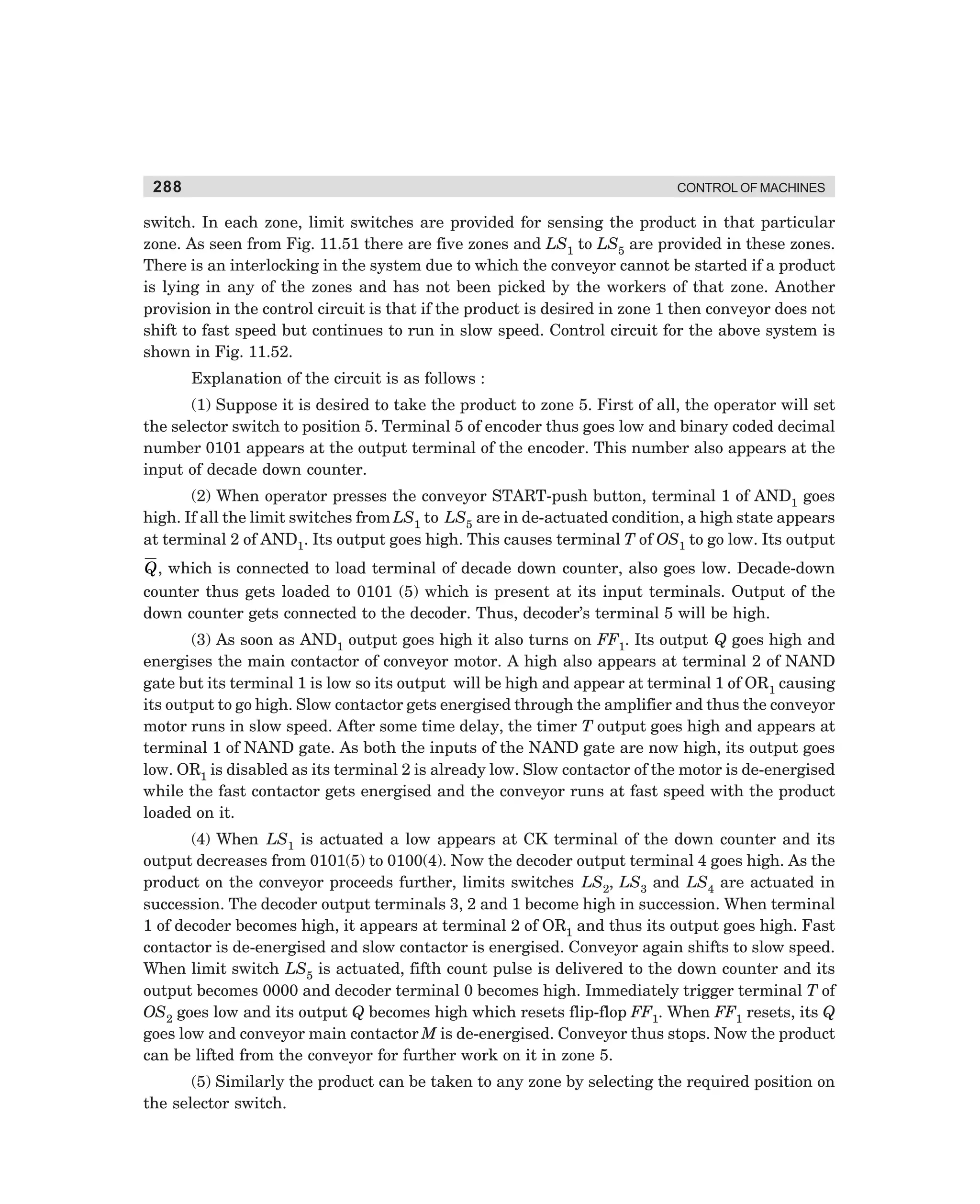
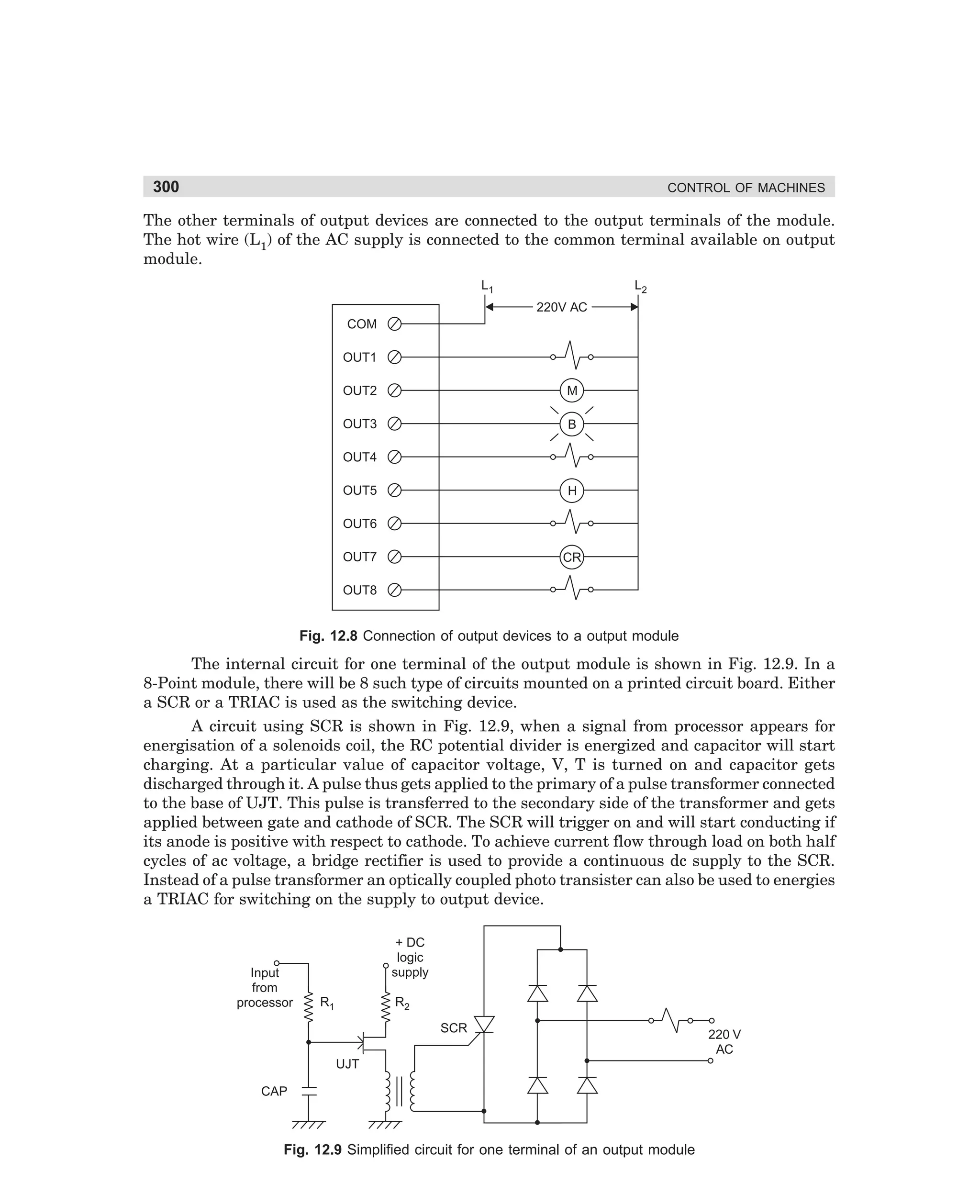
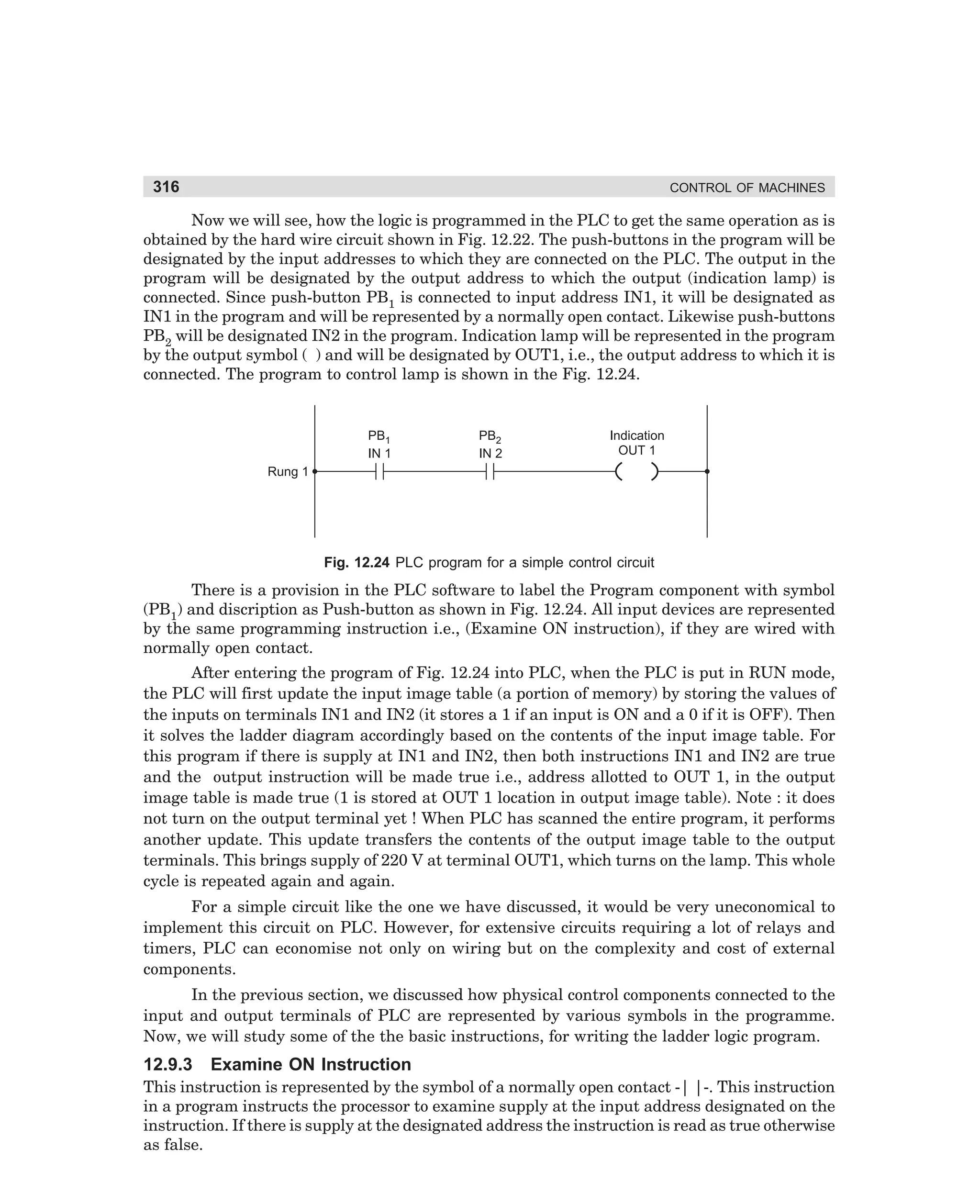
for star-delta closed circuit transition is shown in Fig. 3.30.
The control circuit which accomplishes this control sequence is shown in Fig. 3.31.
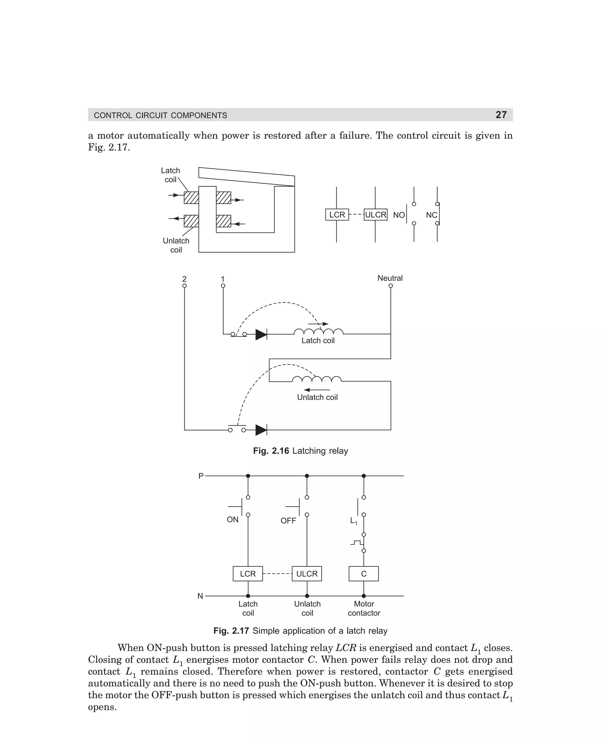
The control operations performed by the circuit of Fig. 3.31 are as follows:
(i) Pressing of the ON-push button energises control relay CR. Its contacts CR1 and
CR2 close. Closing of contact CR2 energises star contactor S.
(ii) Energisation of star contactor S leads to closing of its contact S1 and opening of S2.
Contactor M gets energised through contact S1 and gets hold through its own contact
M1. Thus the motor runs in star connection [see Fig. 3.30 (a)].
(iii) Timer A gets energised along with the main contactor M. Timer operates after a predetermined time and its delayed contact A1 closes to energise contactor T.
(iv) Energisation of contactor T connects a high value resistance in parallel with each of
the windings, the windings being connected in star and the motor continues to run in
star connection [see Fig. 3.30 (b)].
(v) Timer B also gets energised along with contactor T. After some delay the timer operates and its contacts B1 opens and thereby de-energises the star contactor S.
dharm
d:N-MachMac3-2.pm5
93](https://image.slidesharecdn.com/controlofmachines-130110181054-phpapp01-140107230436-phpapp02/75/Controlofmachines-130110181054-phpapp01-110-2048.jpg)
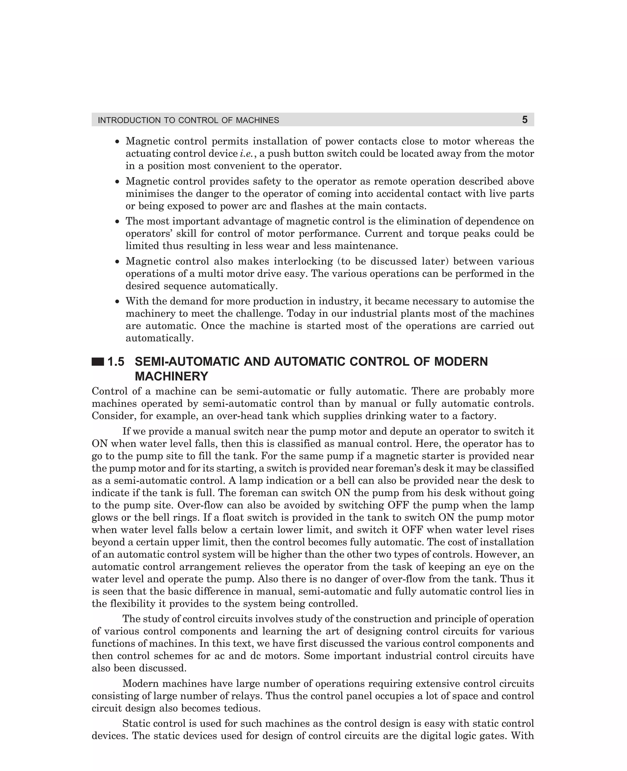
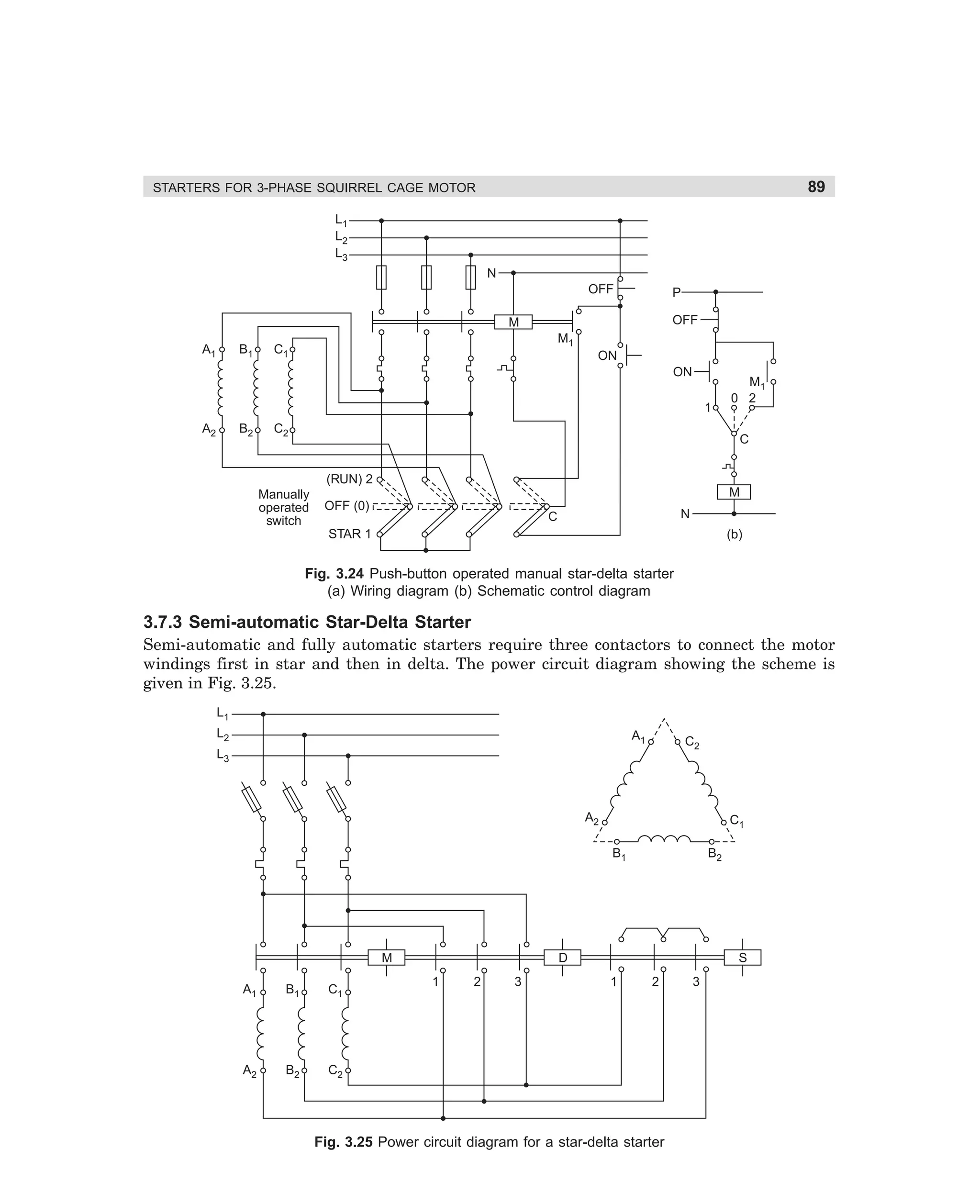
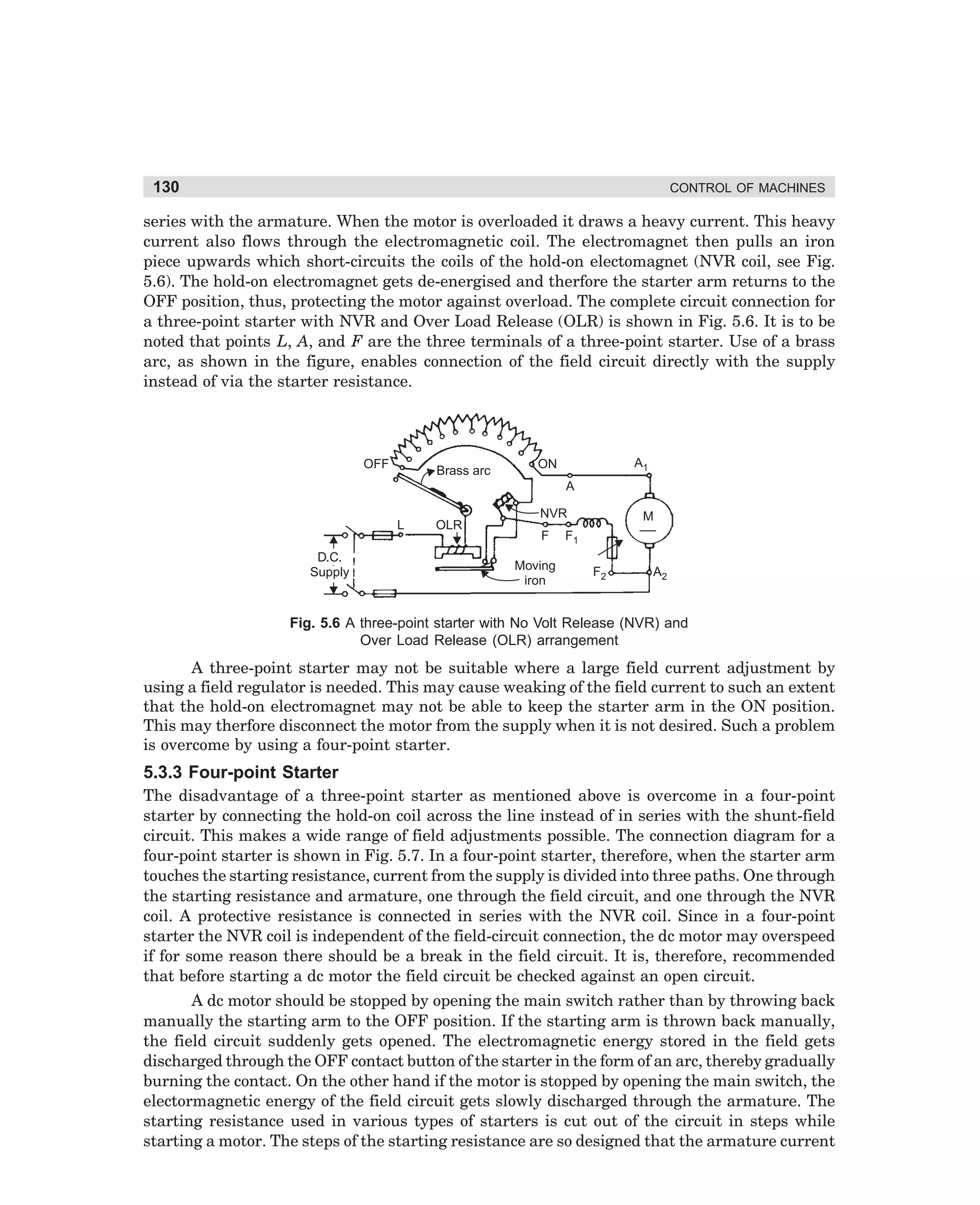
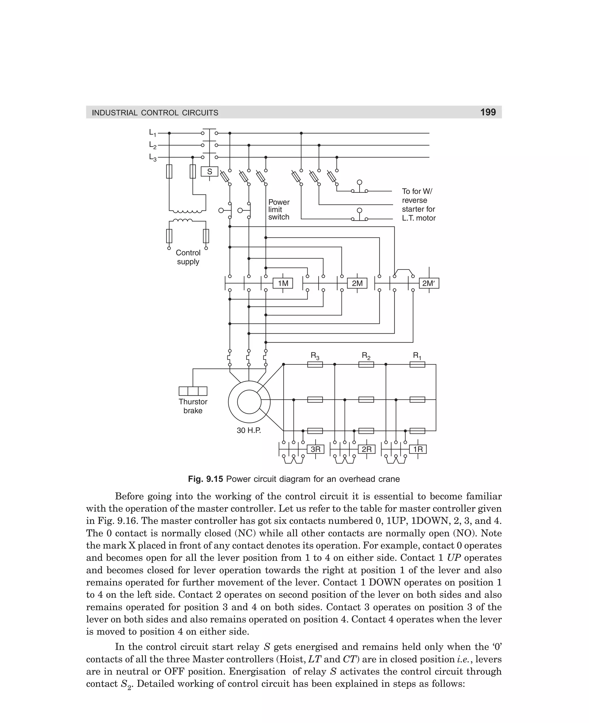
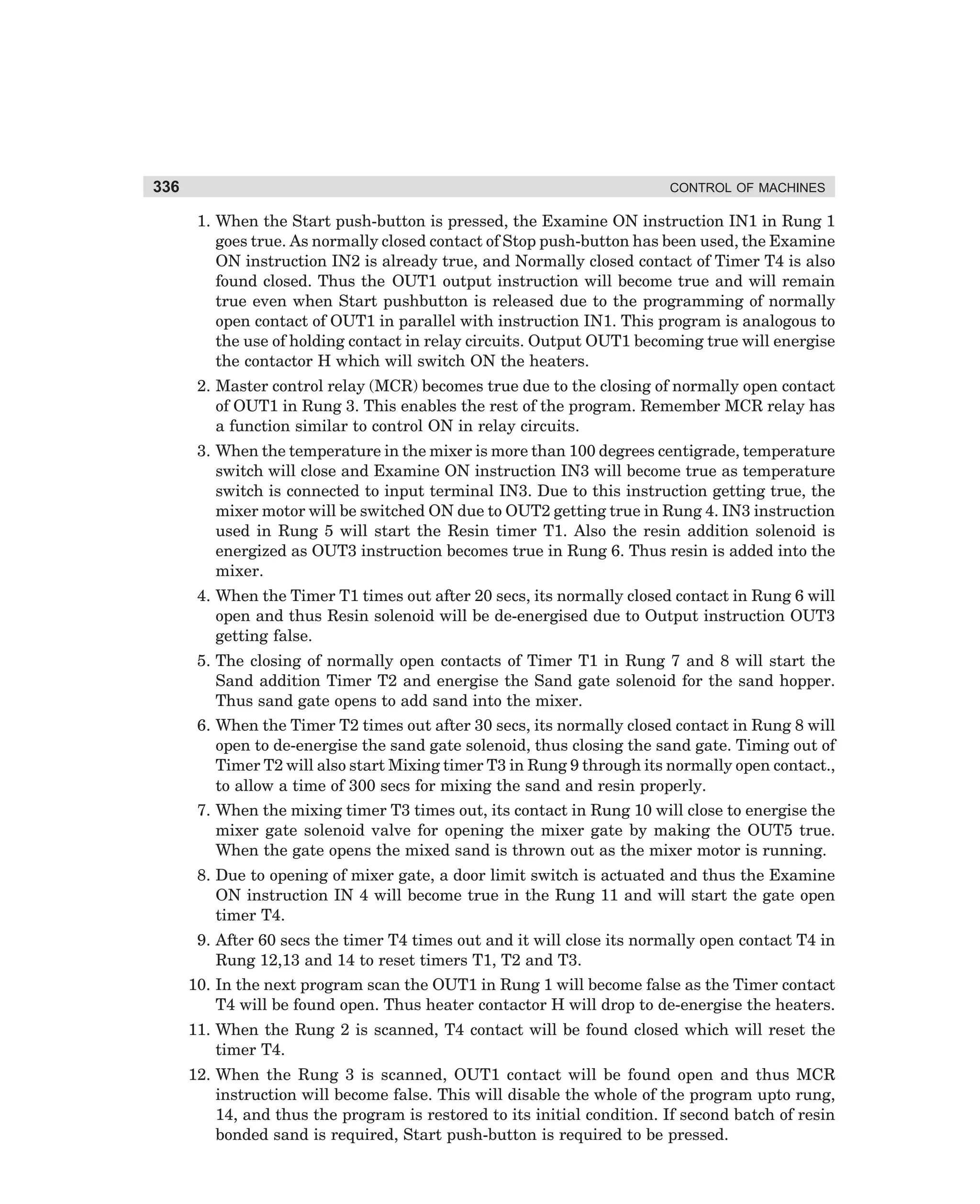
![94
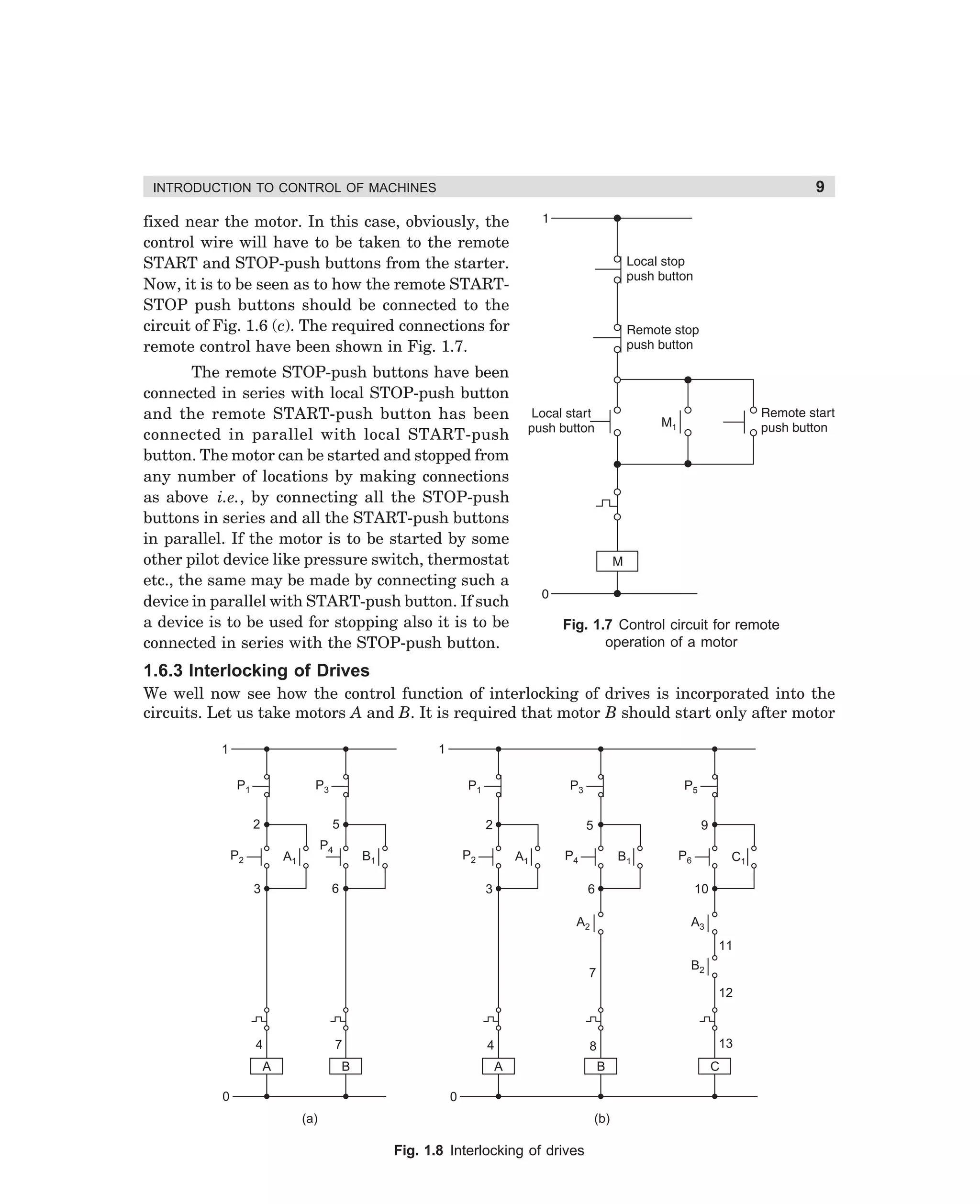
CONTROL OF MACHINES
L1
L2
L3
L1
L2
A1
L3
A1
A2 C2
A2 C2
B2
B2
B1
C1
C1
(a)
(b)
B1
(2) Contactor T closes
(S and M also closed)
(1) Contactor S and
M close
L1
L2
L3
L1
L2
A1
A1
C2
A2
(d)
L2
L3
Contactor
Operation
A1
C2
Start
A2
B2
(4) Contactor D closes
(While M and T are ON)
(3) Contactor S opens
(While M and T are closed)
L1
C1
B1
B1
(c)
C1
B1
C2
A2
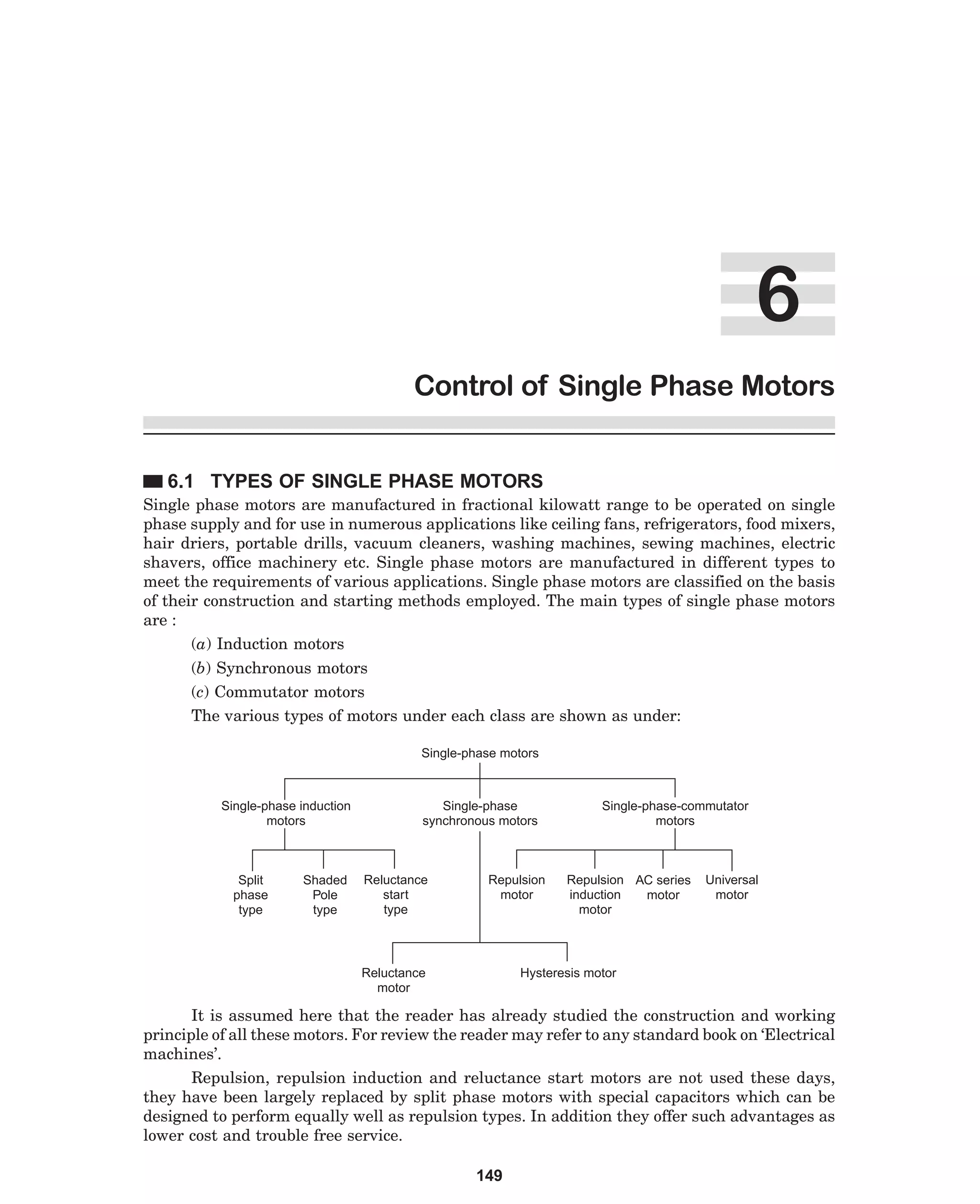
B2
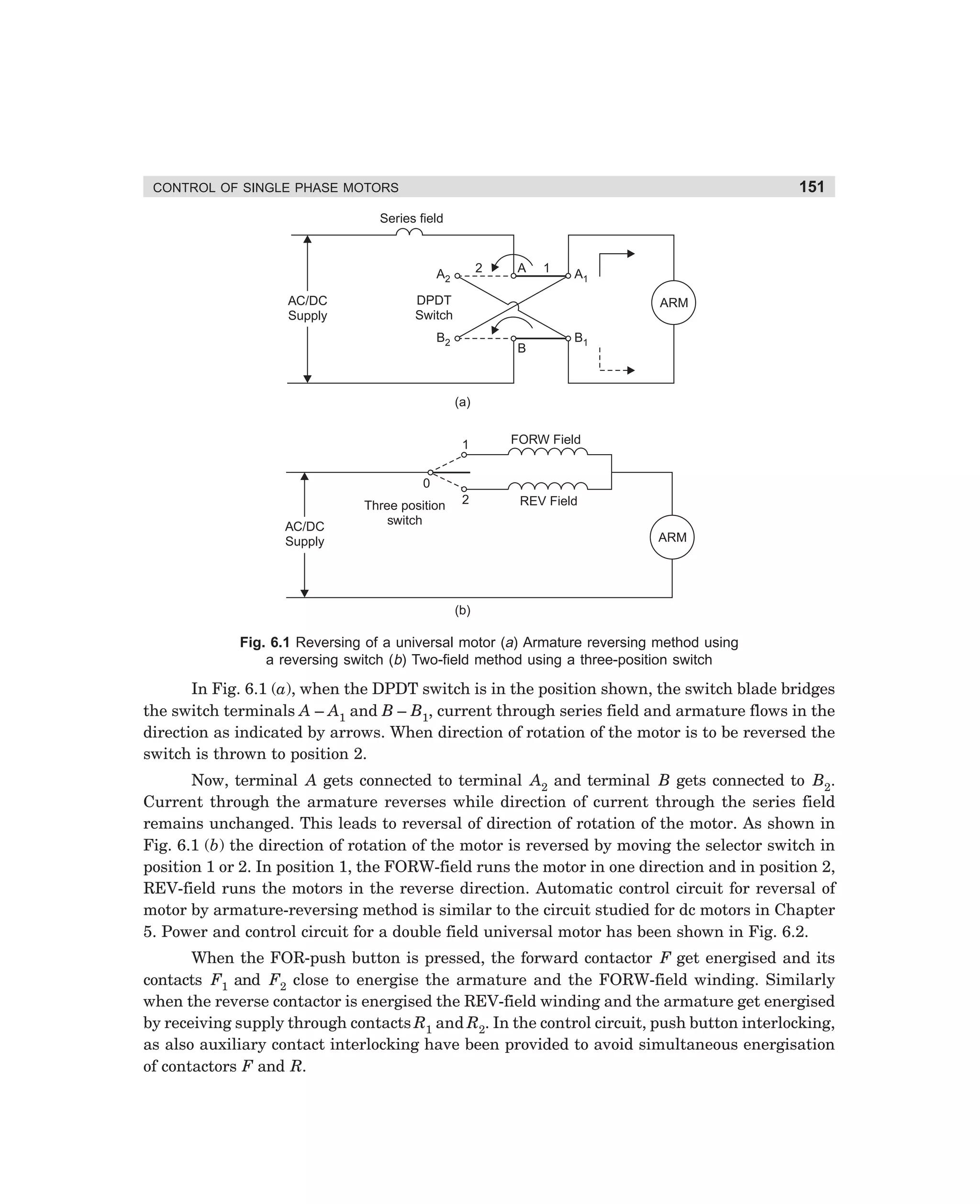
C1
L3
Transition
1
Transition
2
Run
(Delta)
S
X
M
X
T
X
X
X
X
X
X
X
X
X
D
X
B2
(5) Contactor T opens
(While M and D are closed)
Note: X indicates closed condition
(6) Contactor operating sequence
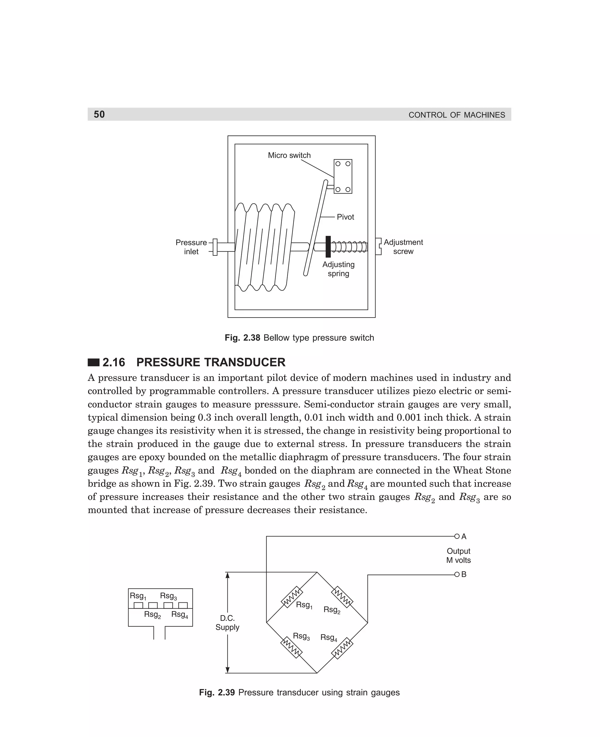
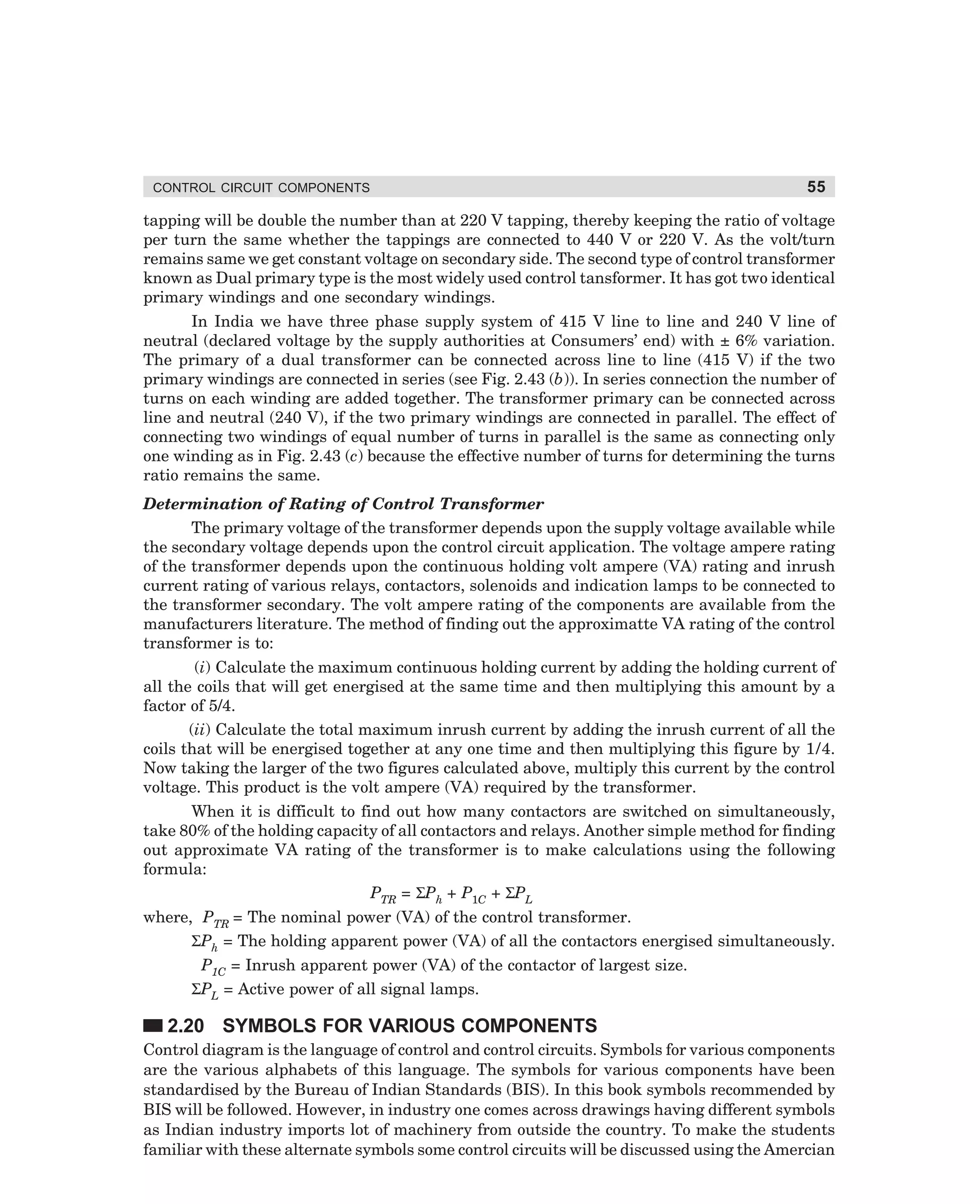
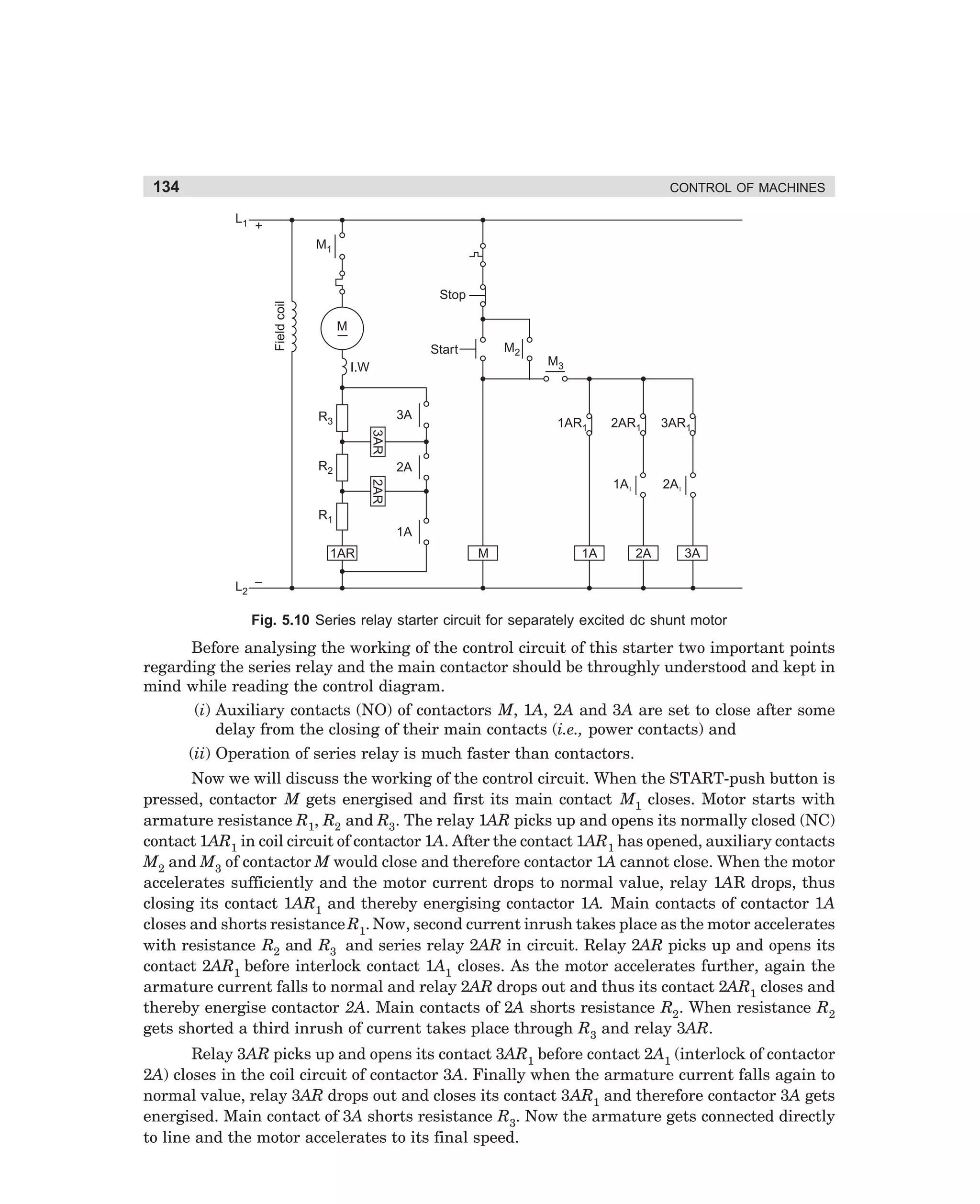
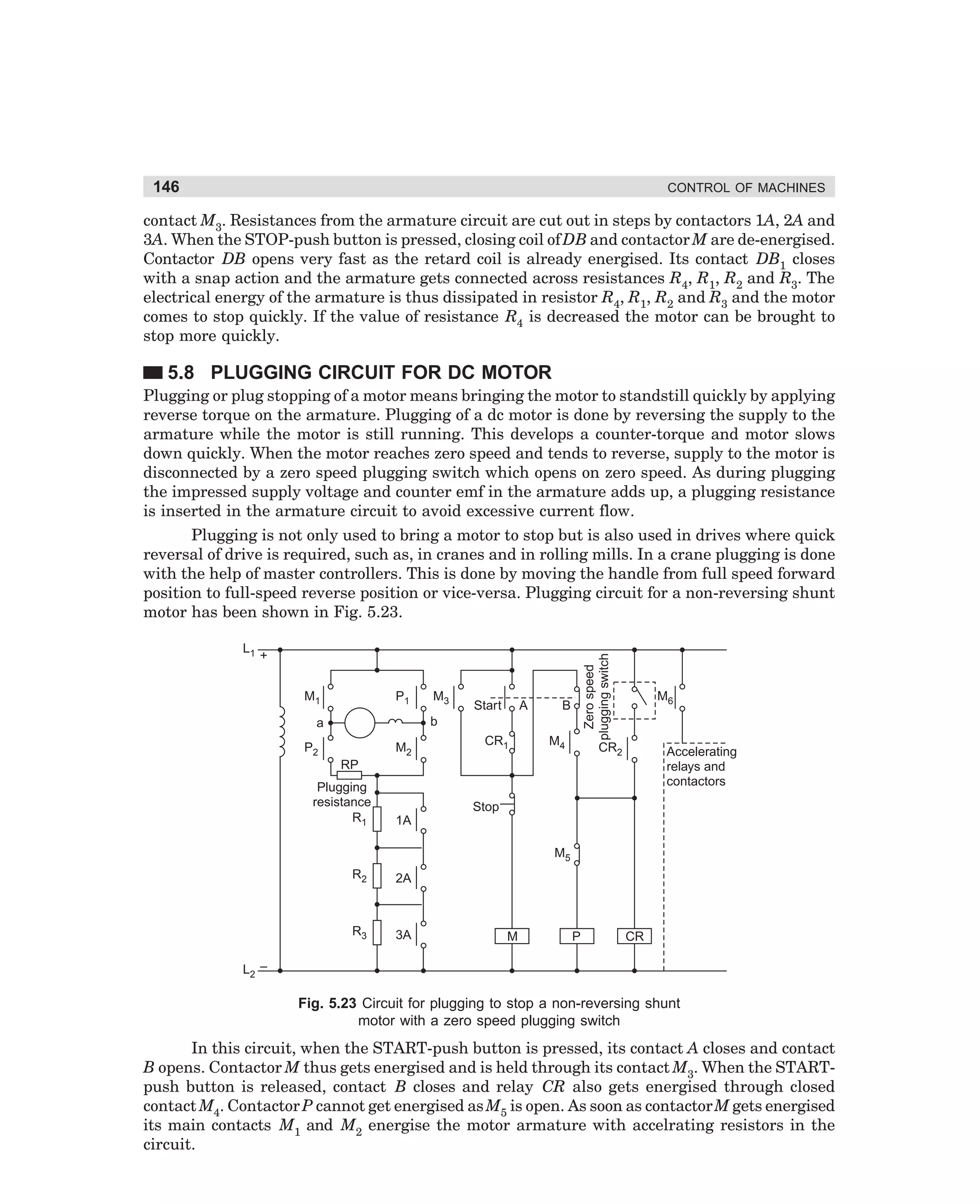
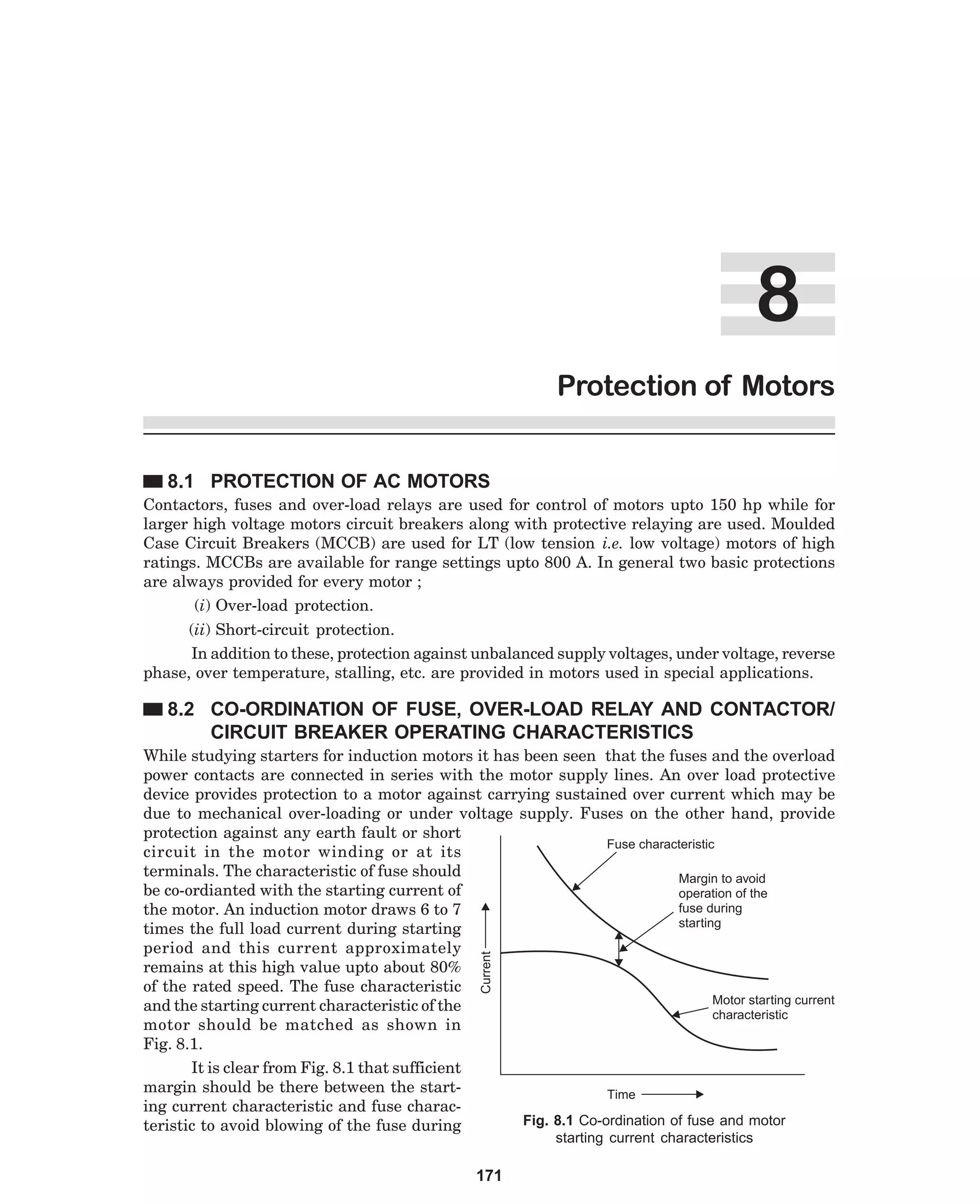
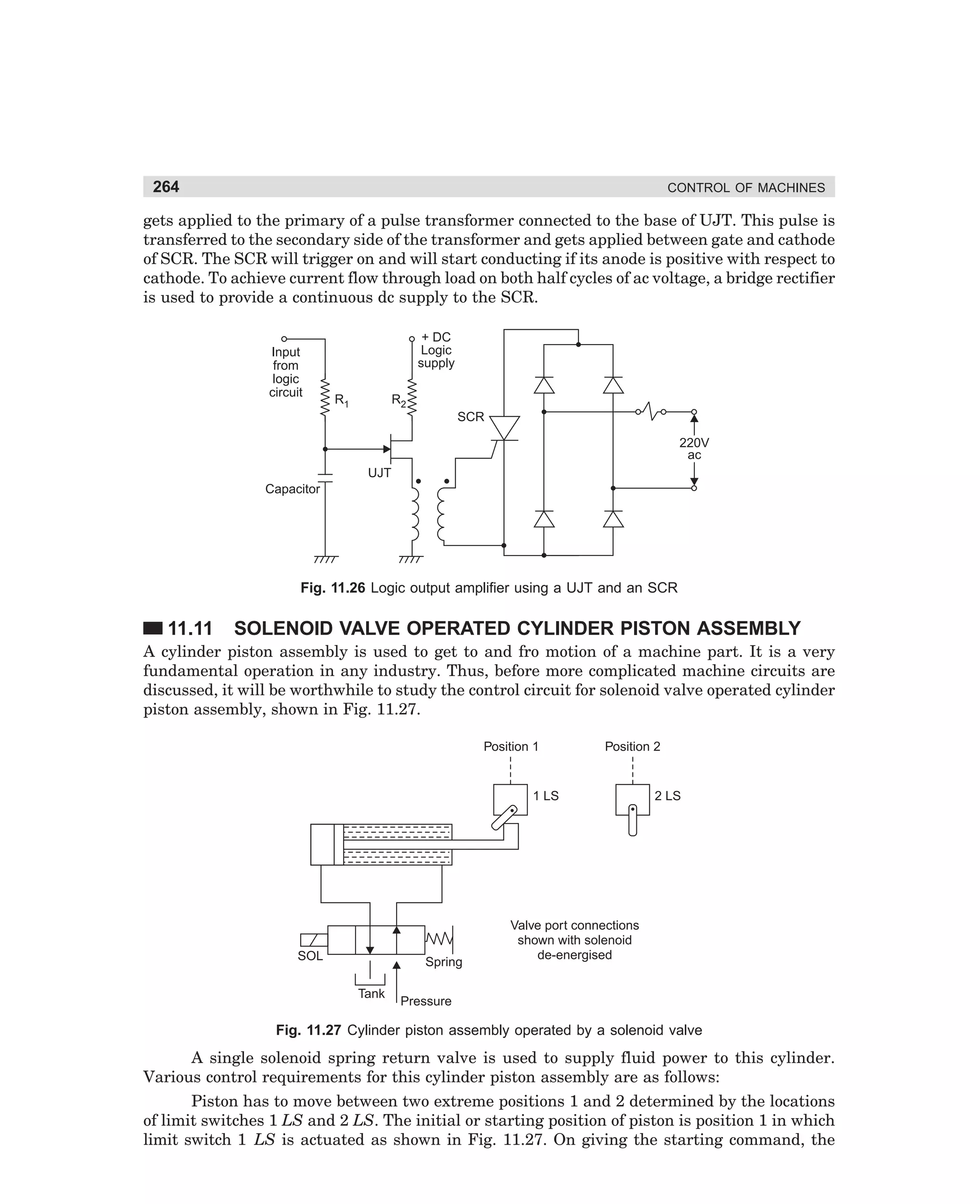
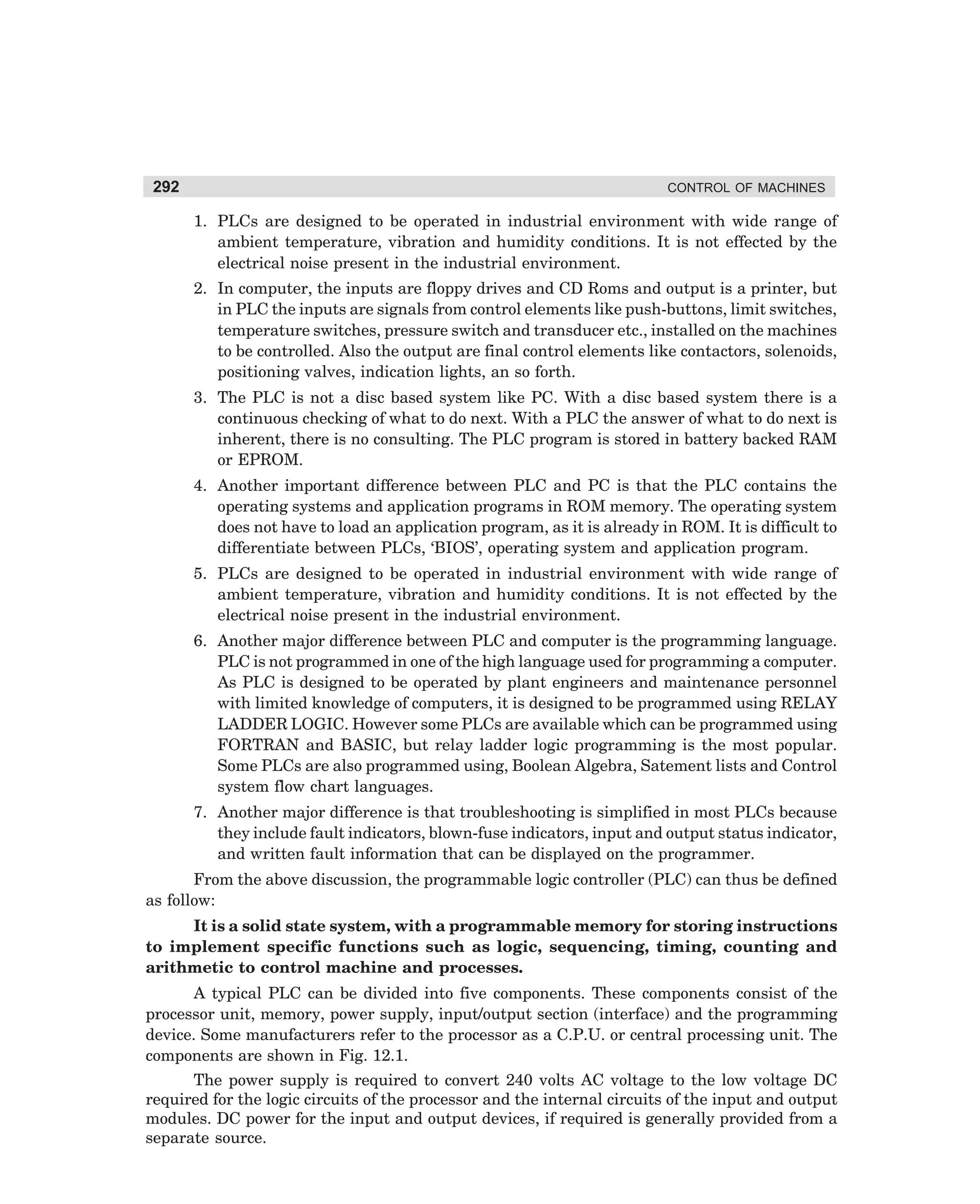
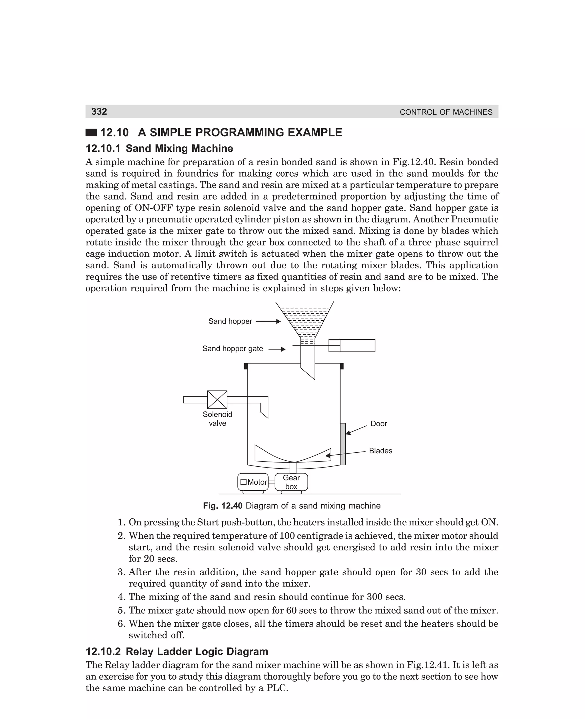
Fig. 3.30 Operating sequence of a closed circuit transition star-delta starter
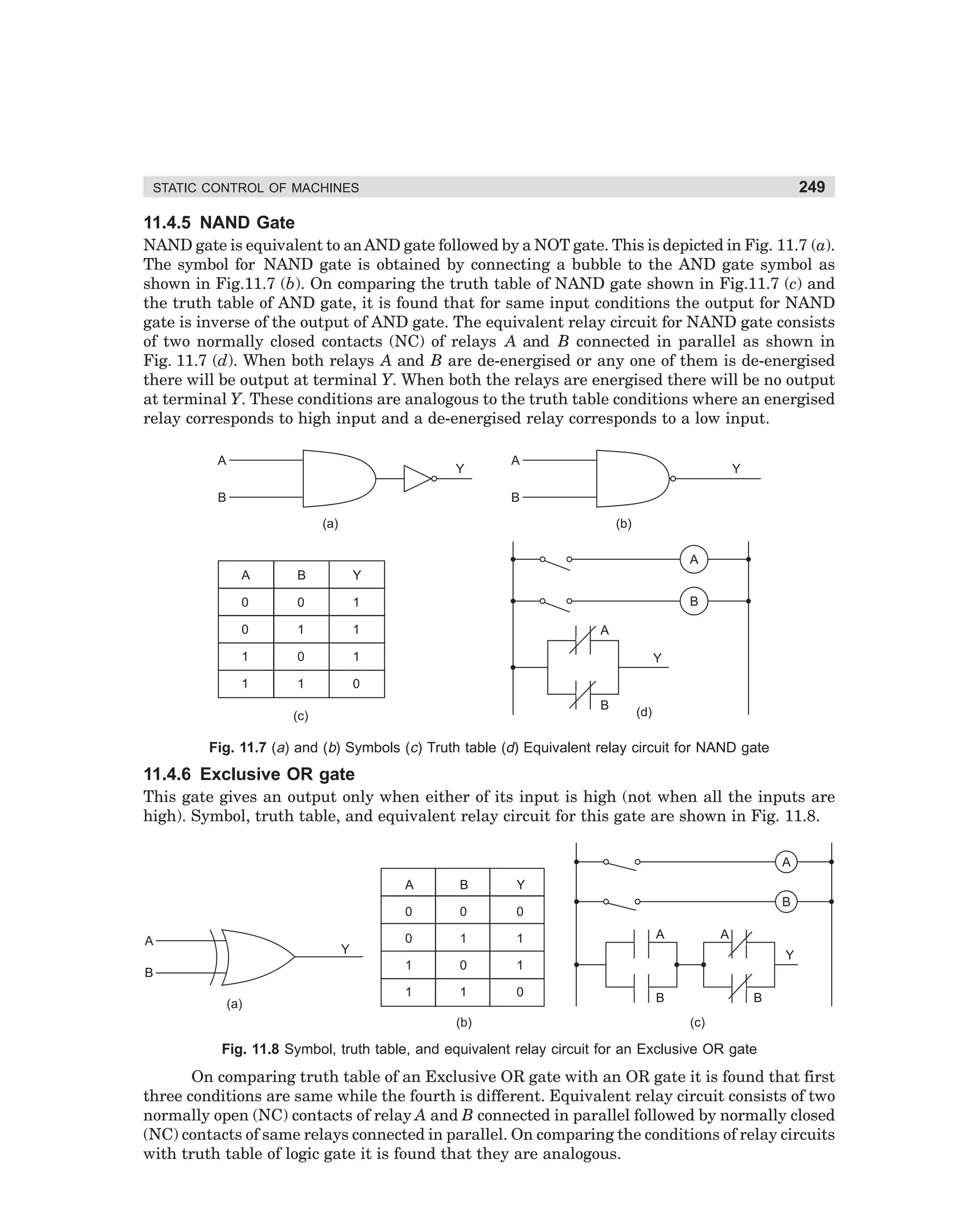
(vi) De-energisation of contactor S leads to closing of the contact S2 and thus the delta
contactor D is energised. During the gap between opening of star contactor and closing of delta contactor, contactor T connects the winding in delta with resistances in
series [see Fig. 3.30 (c) and (d)].
(vii) Energisation of contactor D leads to opening of its contacts D1 and D2. Contact D1
opens to provide interlocking with contactor S while opening of contact D2 de-energises contactor T and resets timer A and timer B by de-energising their coils.
dharm
d:N-MachMac3-2.pm5
94](https://image.slidesharecdn.com/controlofmachines-130110181054-phpapp01-140107230436-phpapp02/75/Controlofmachines-130110181054-phpapp01-111-2048.jpg)
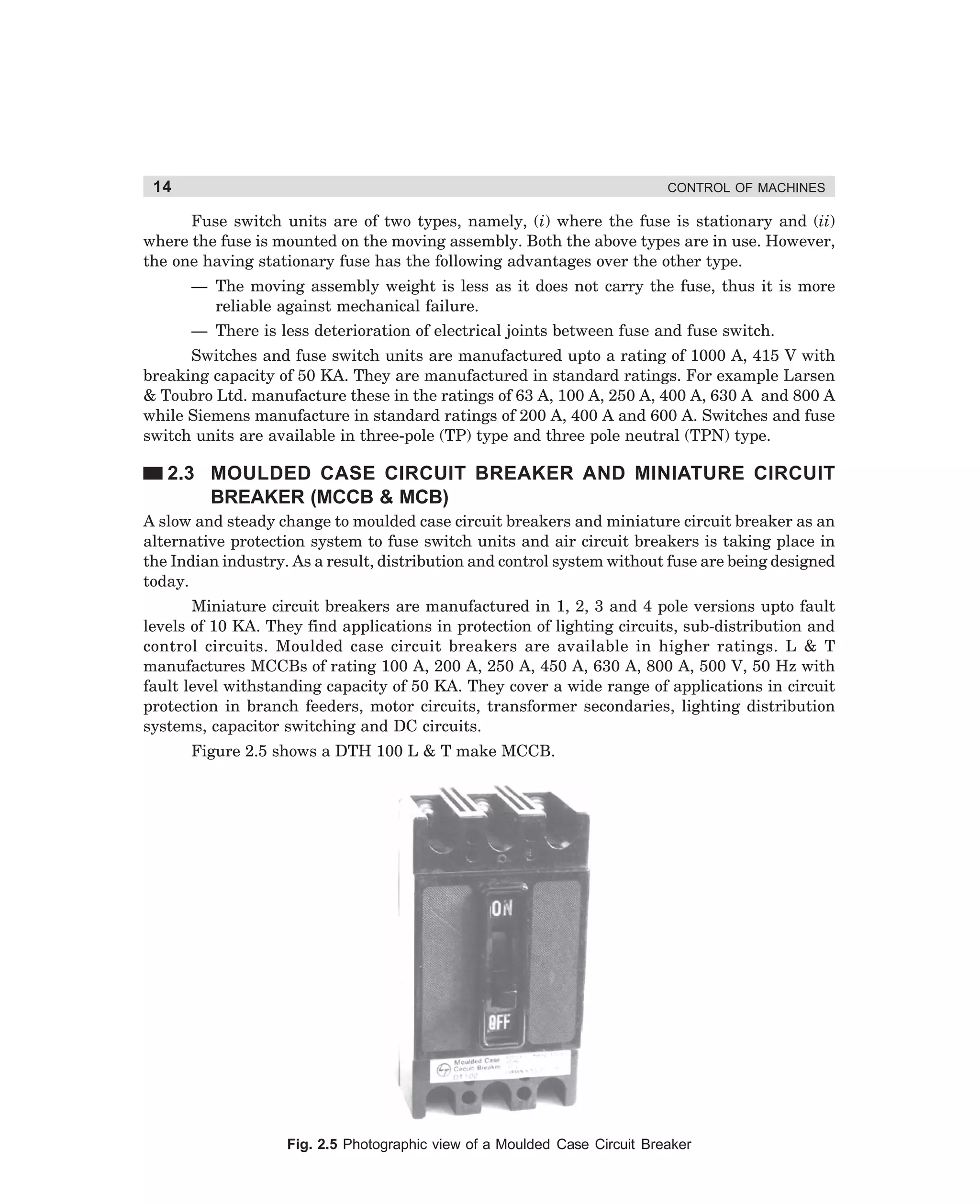
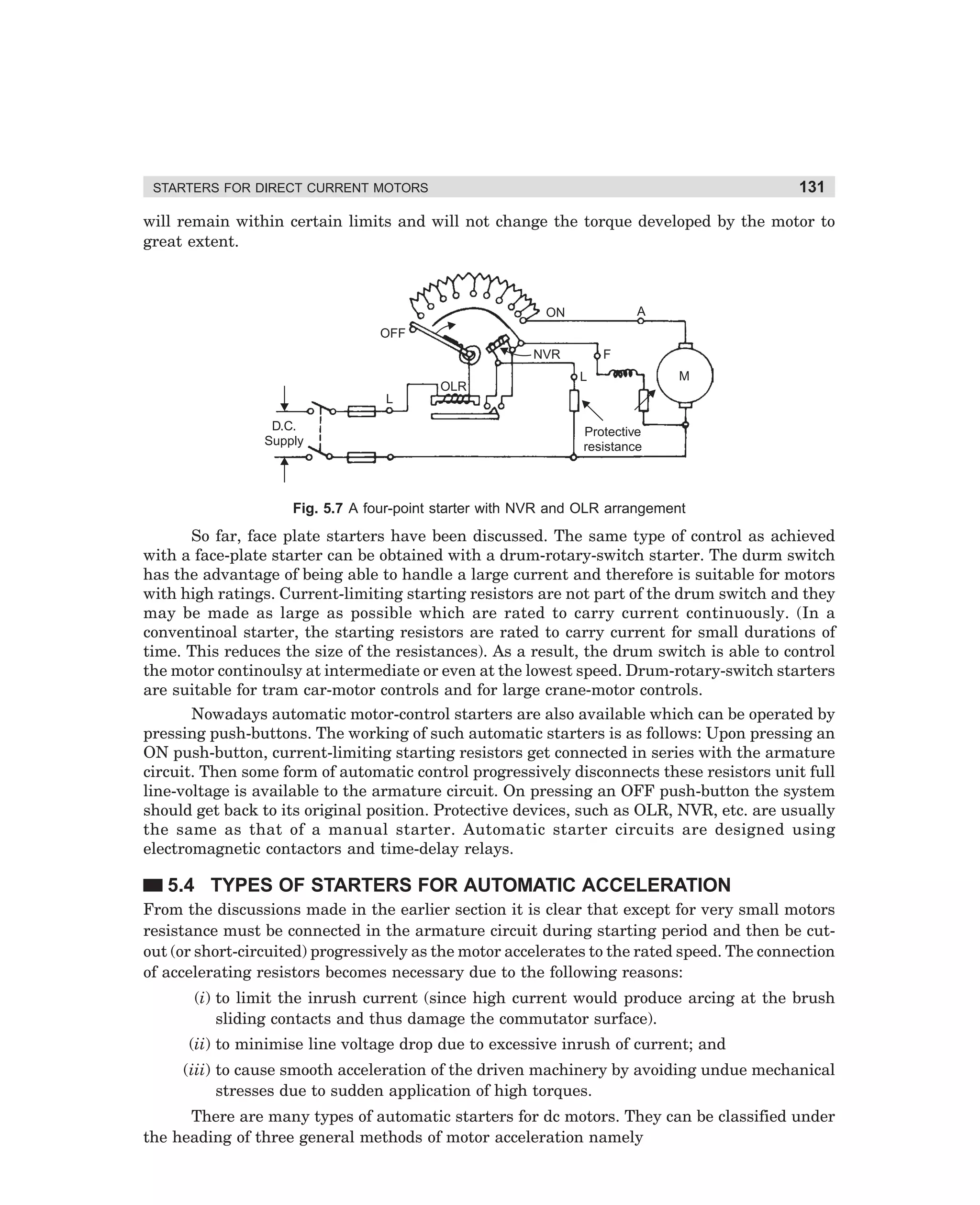
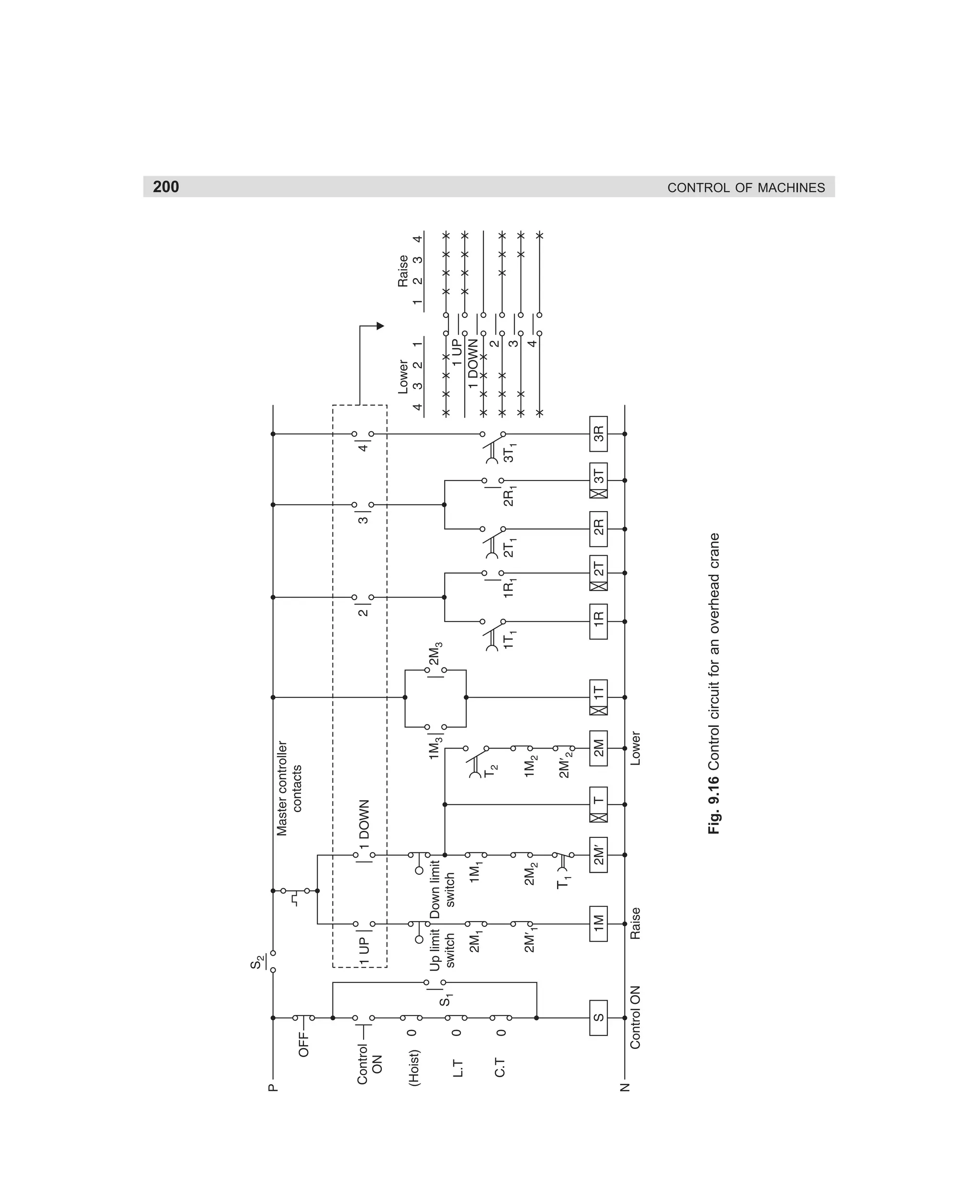
![95
STARTERS FOR 3-PHASE SQUIRREL CAGE MOTOR
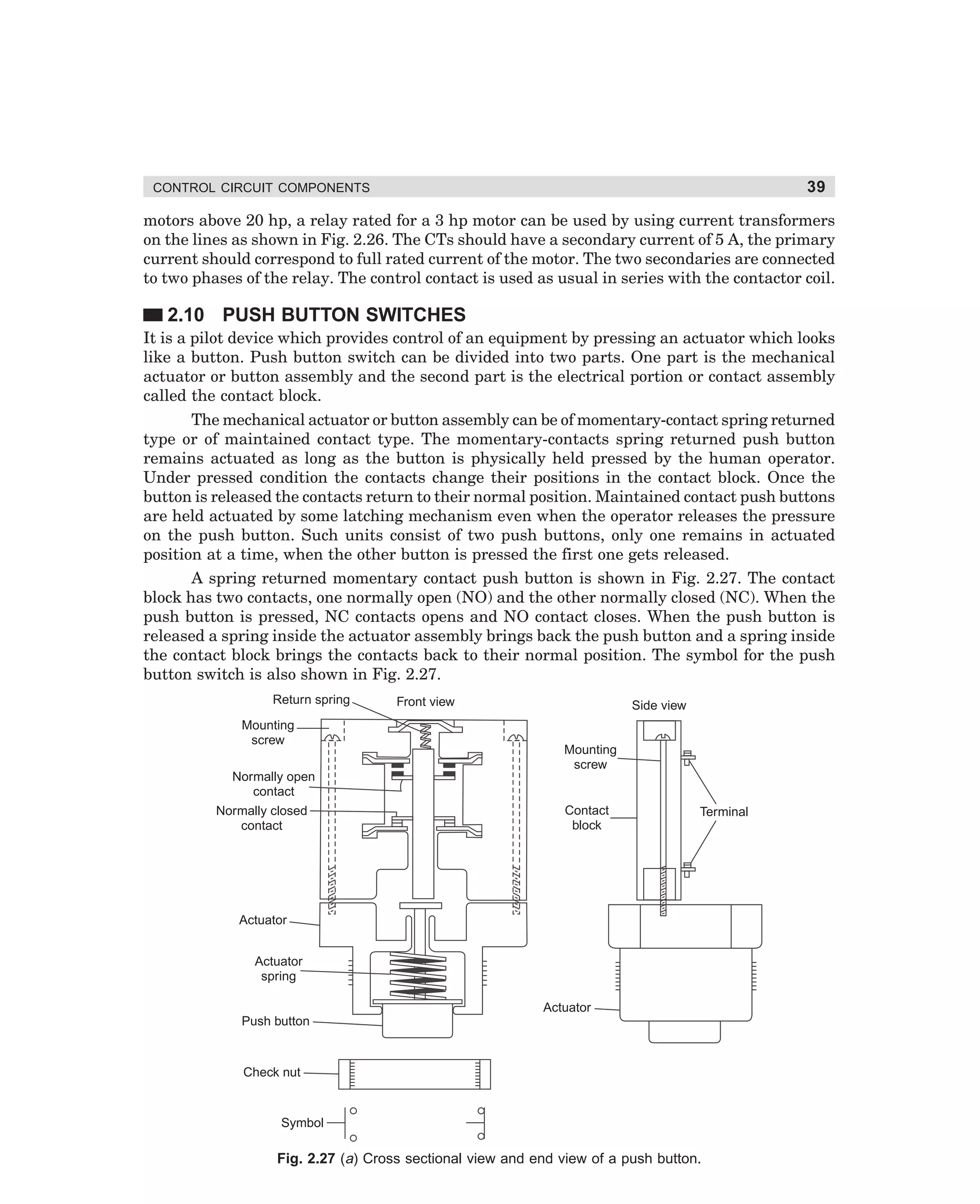
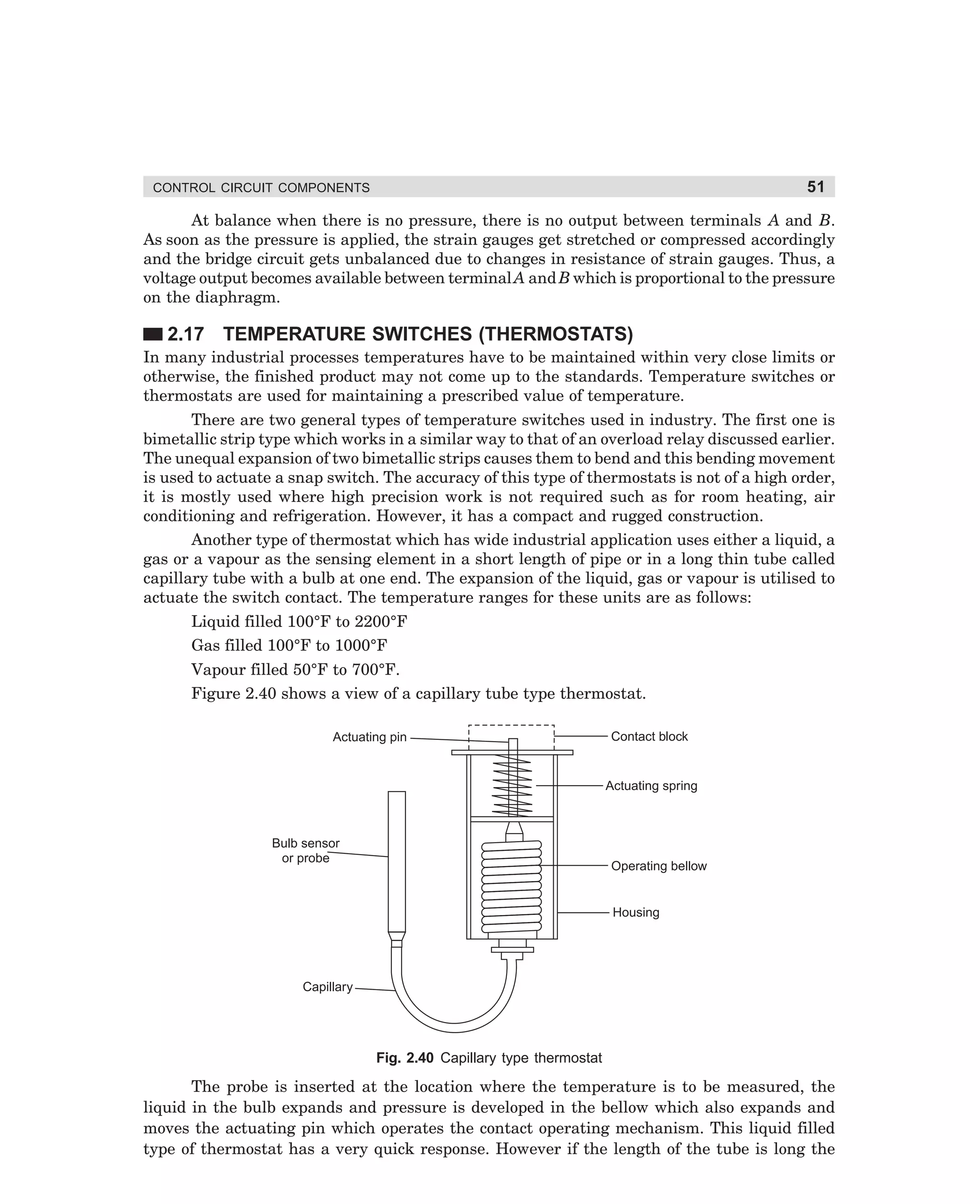
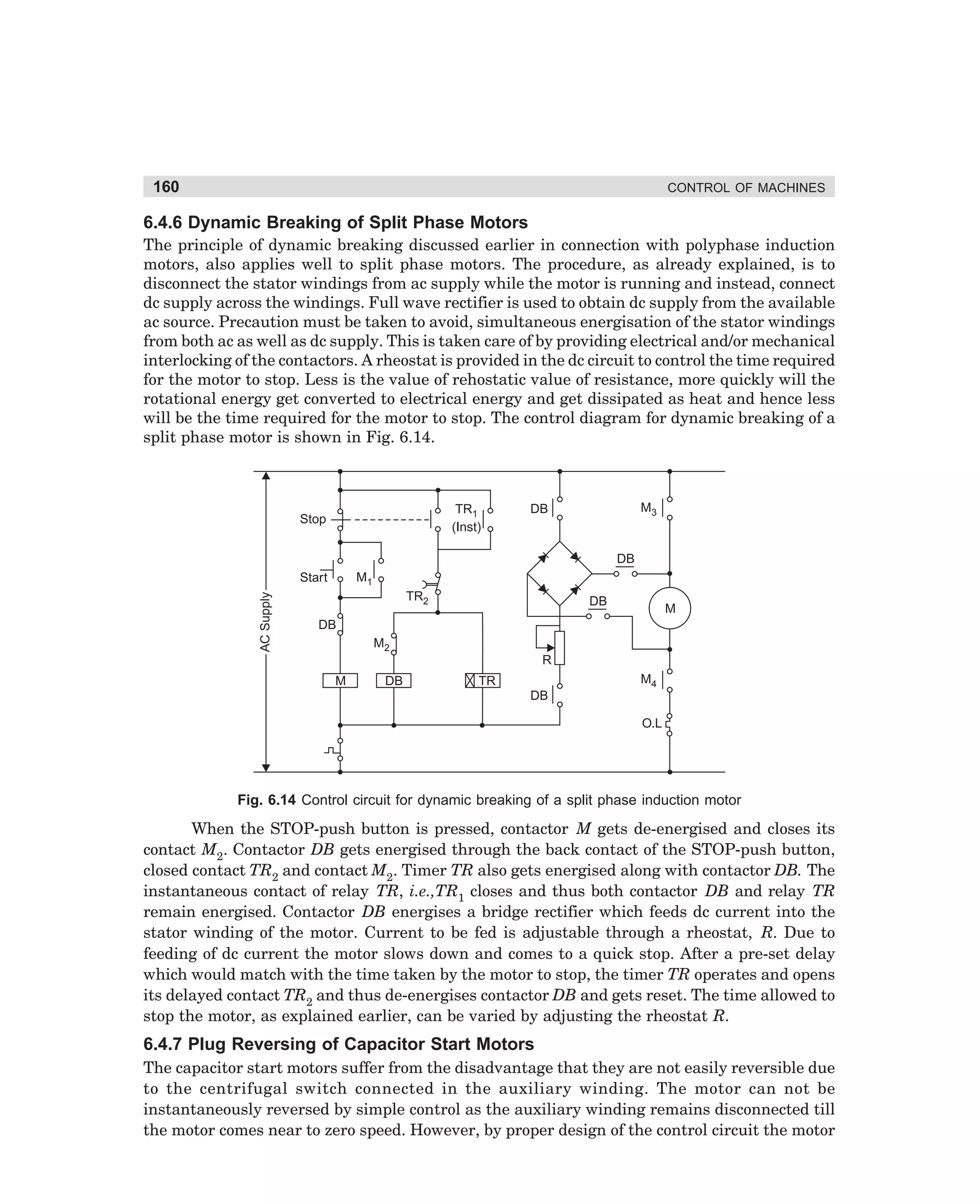
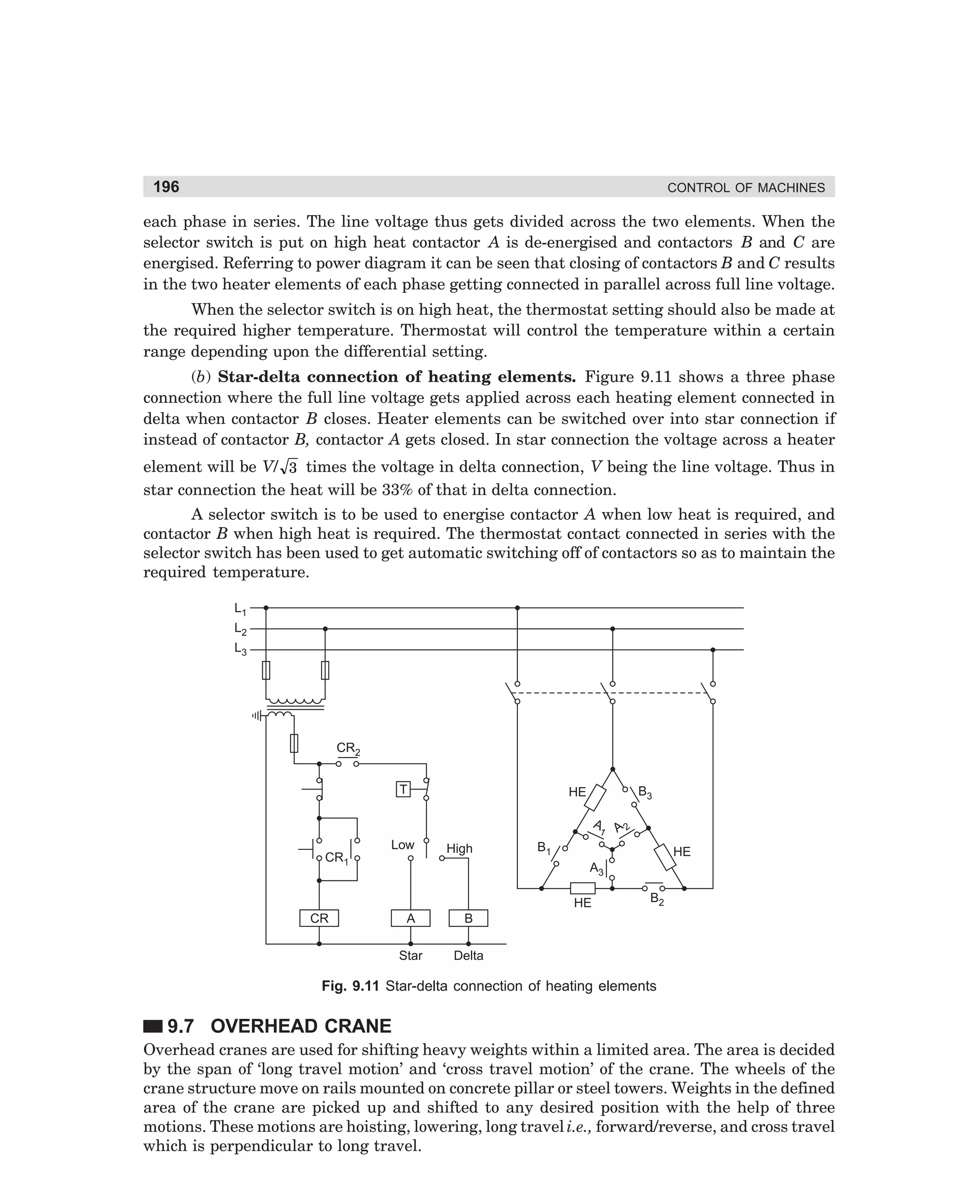
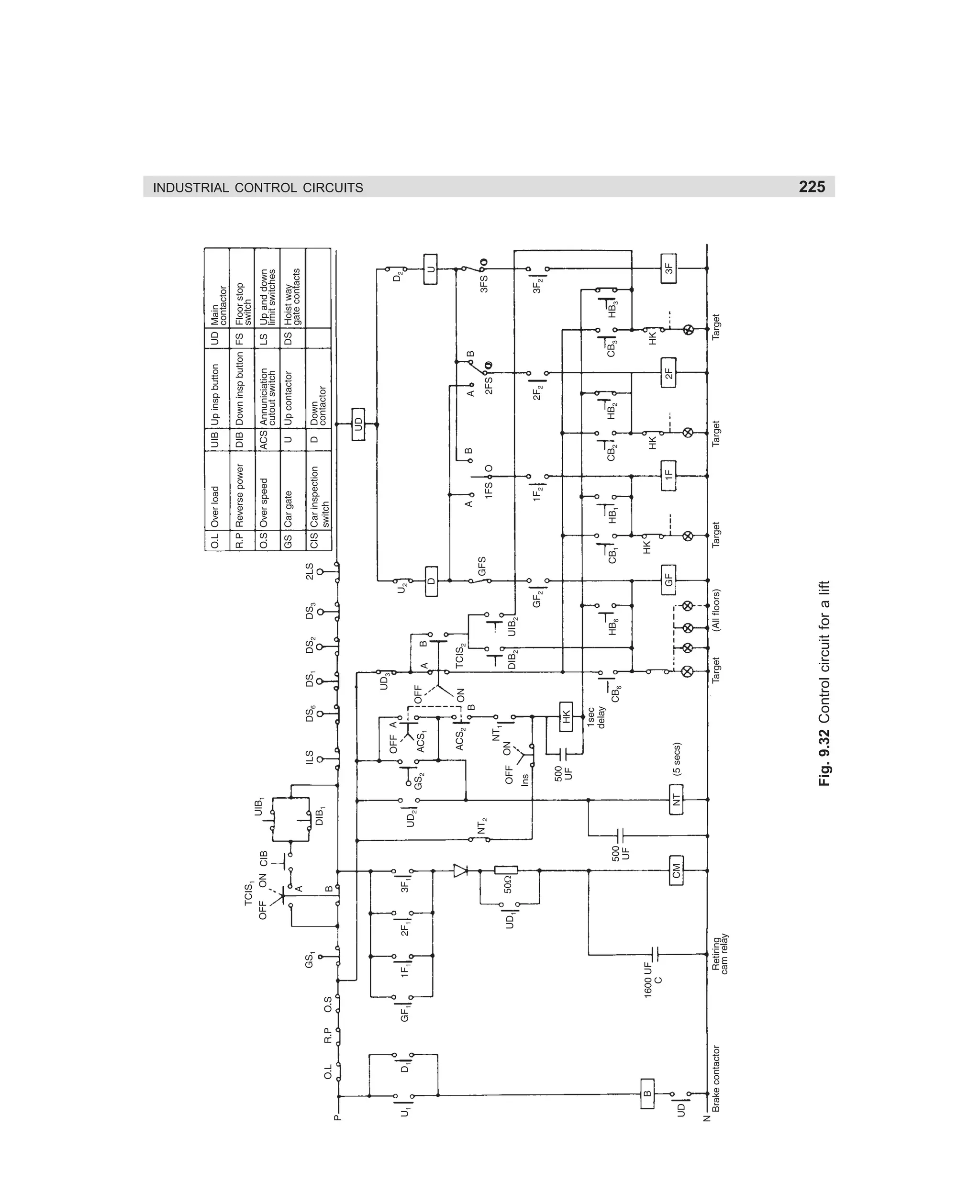
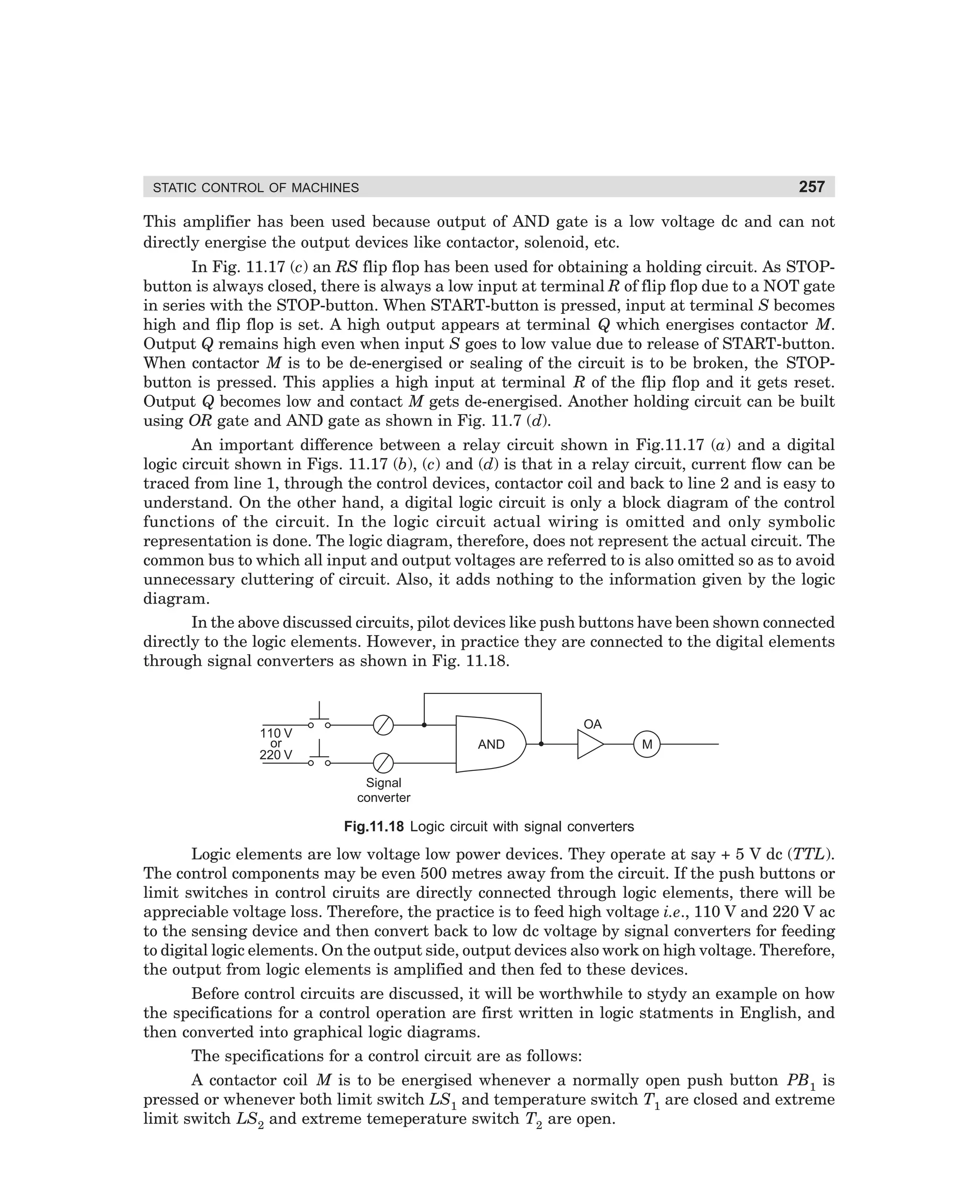
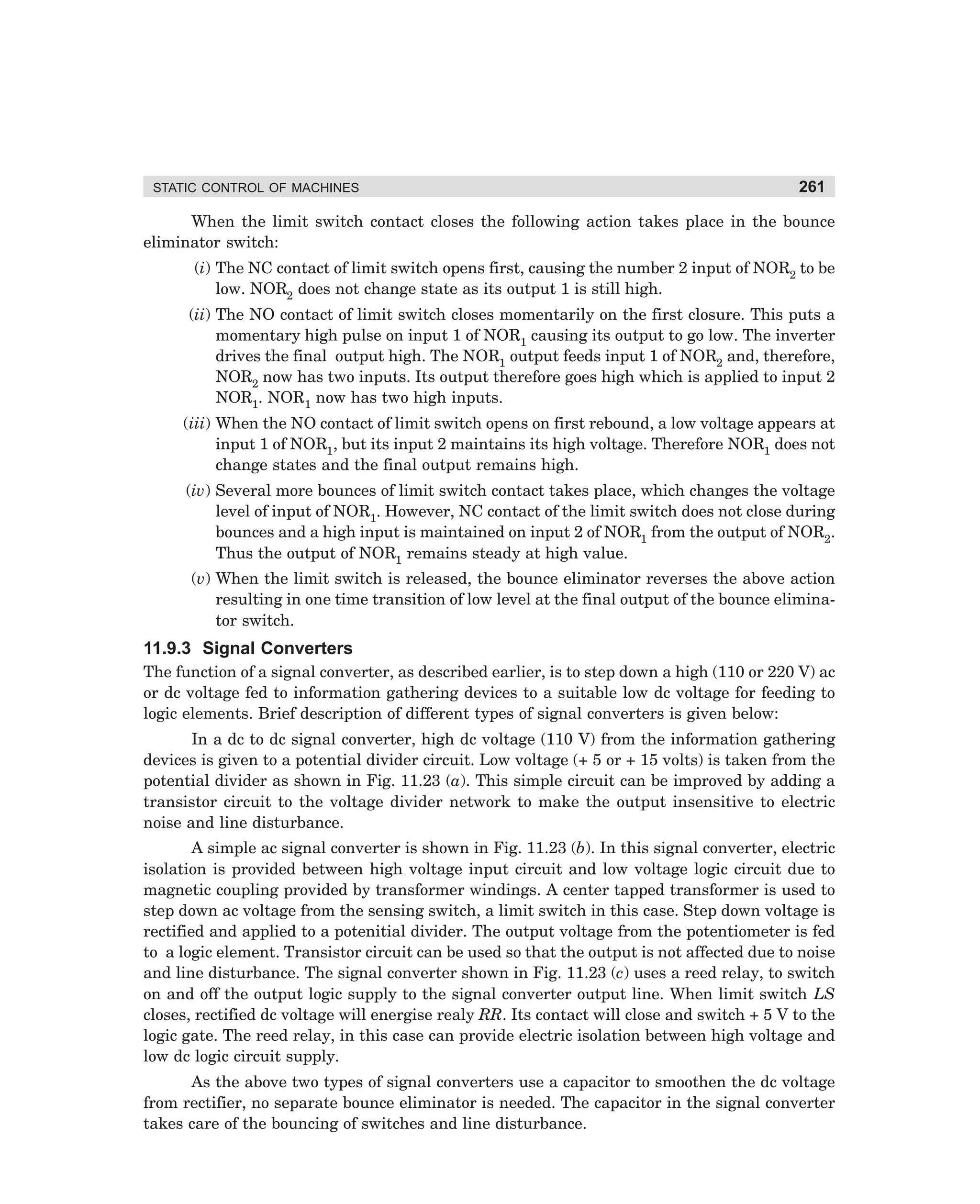
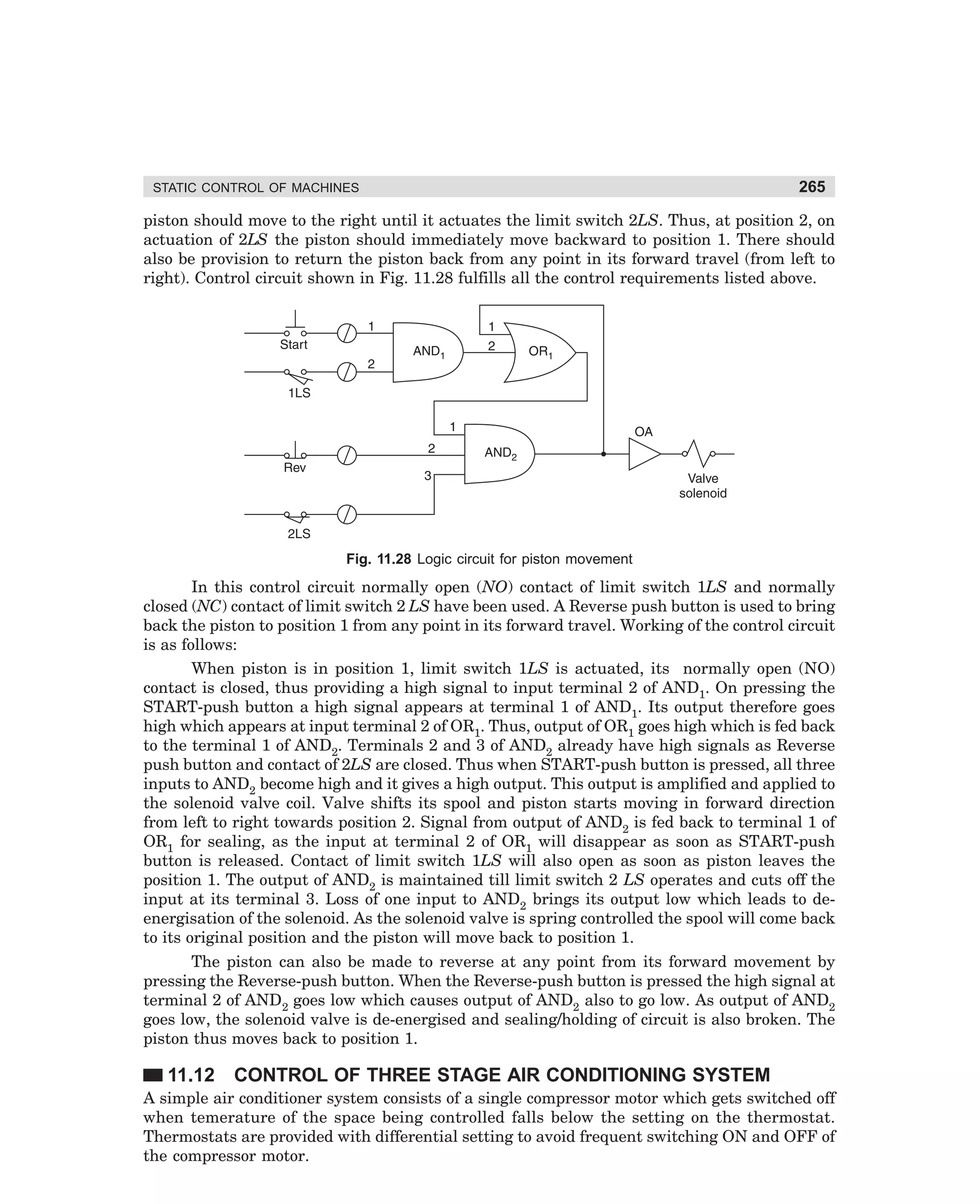
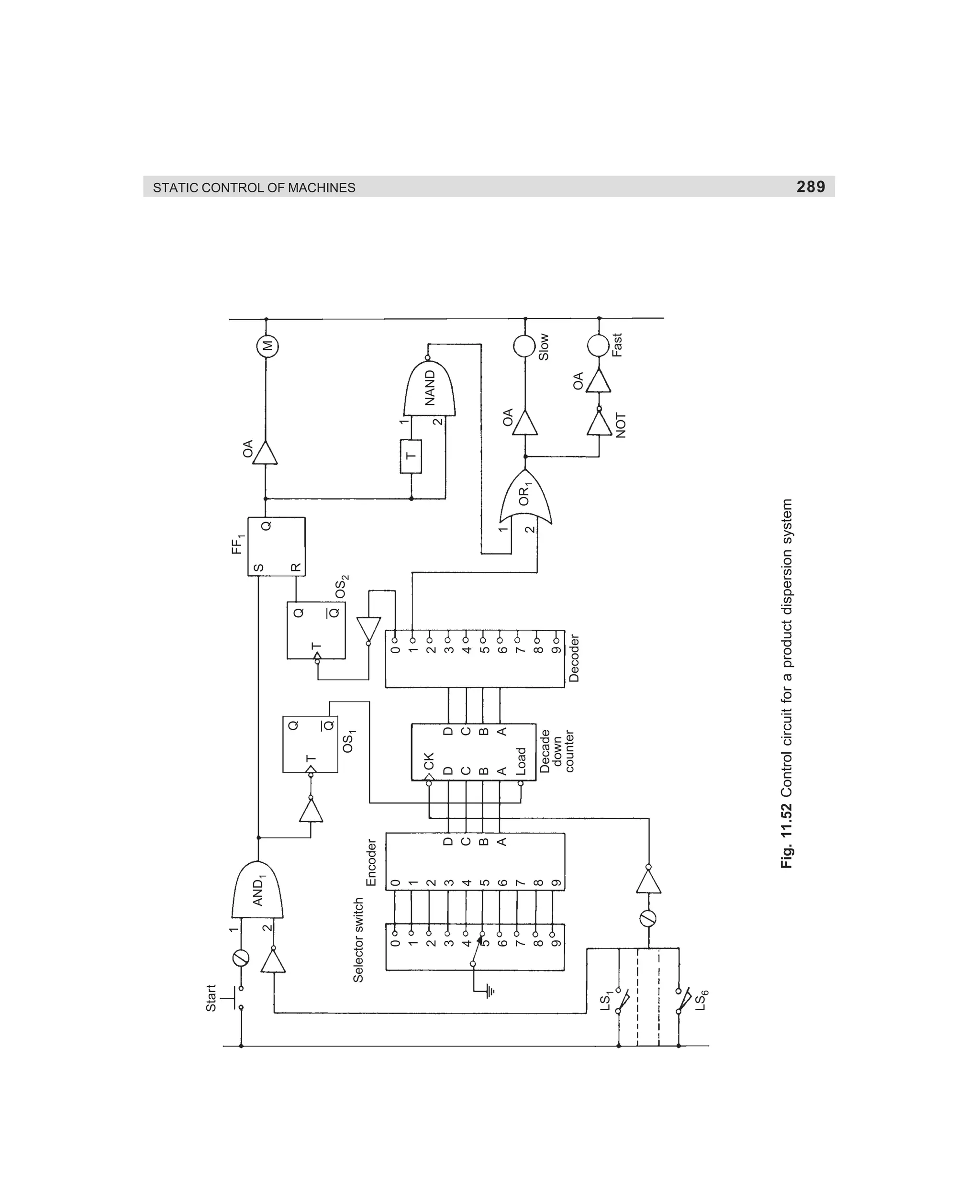
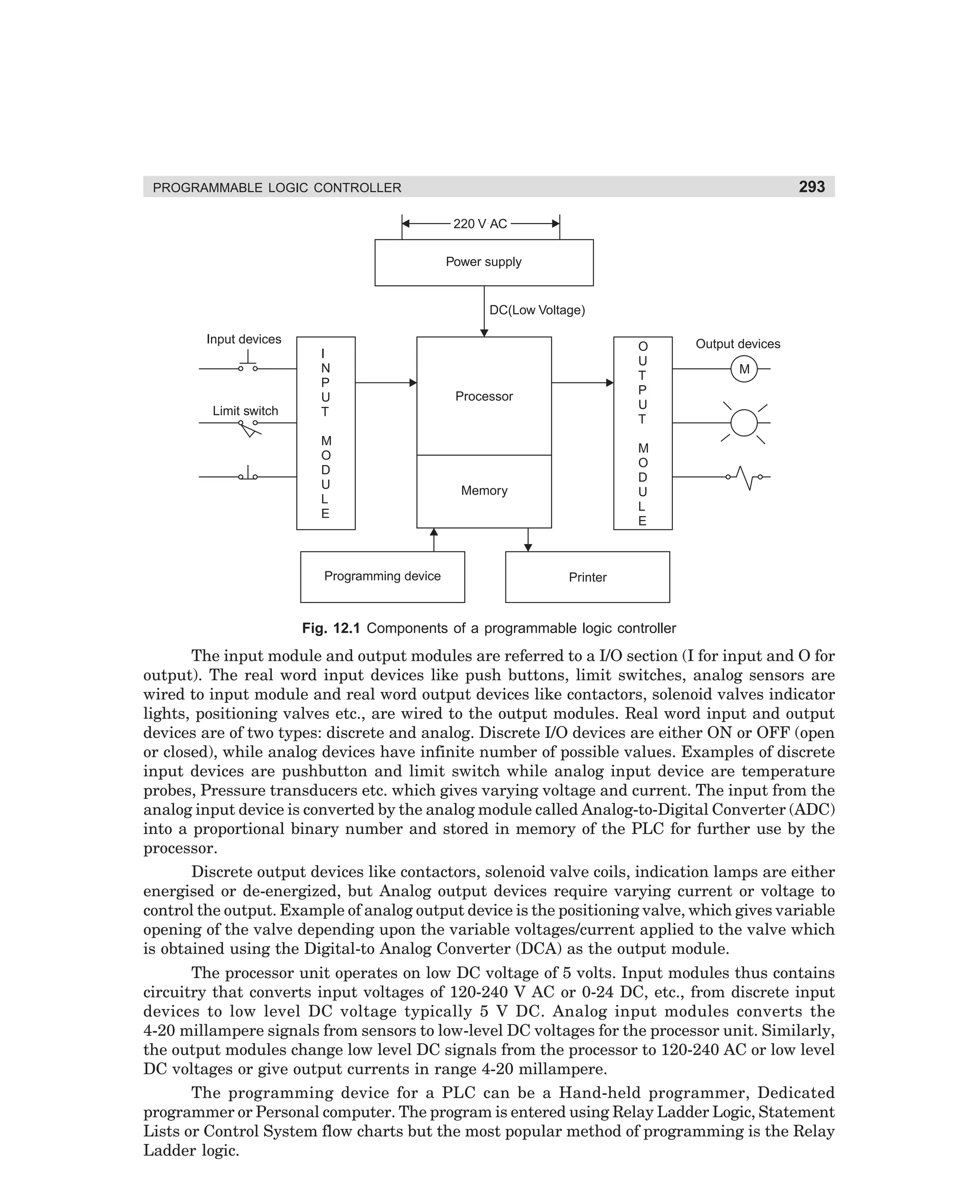
(viii) In the run condition motor runs in delta connection with contactor M and D energised [see Fig. 3.30 (d)].
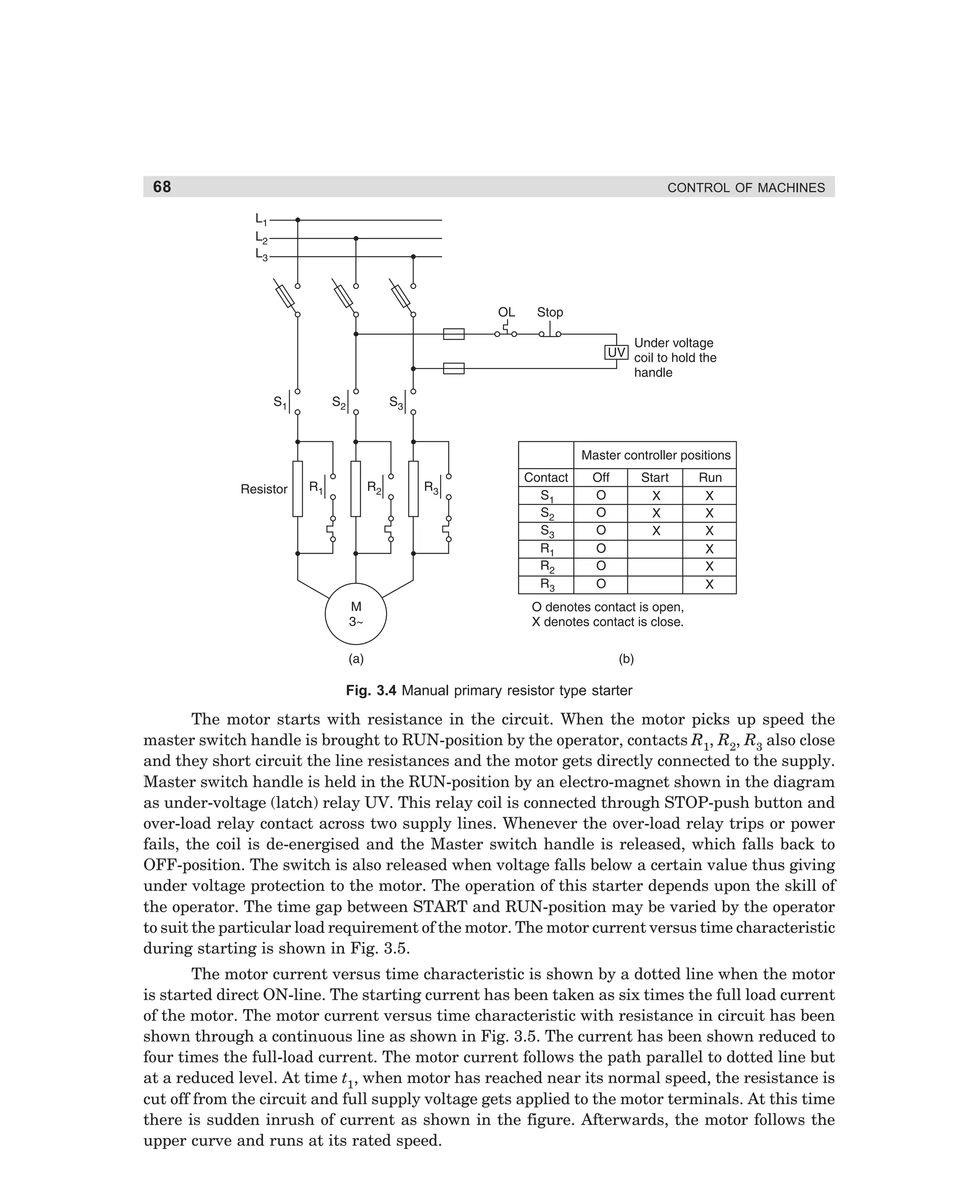
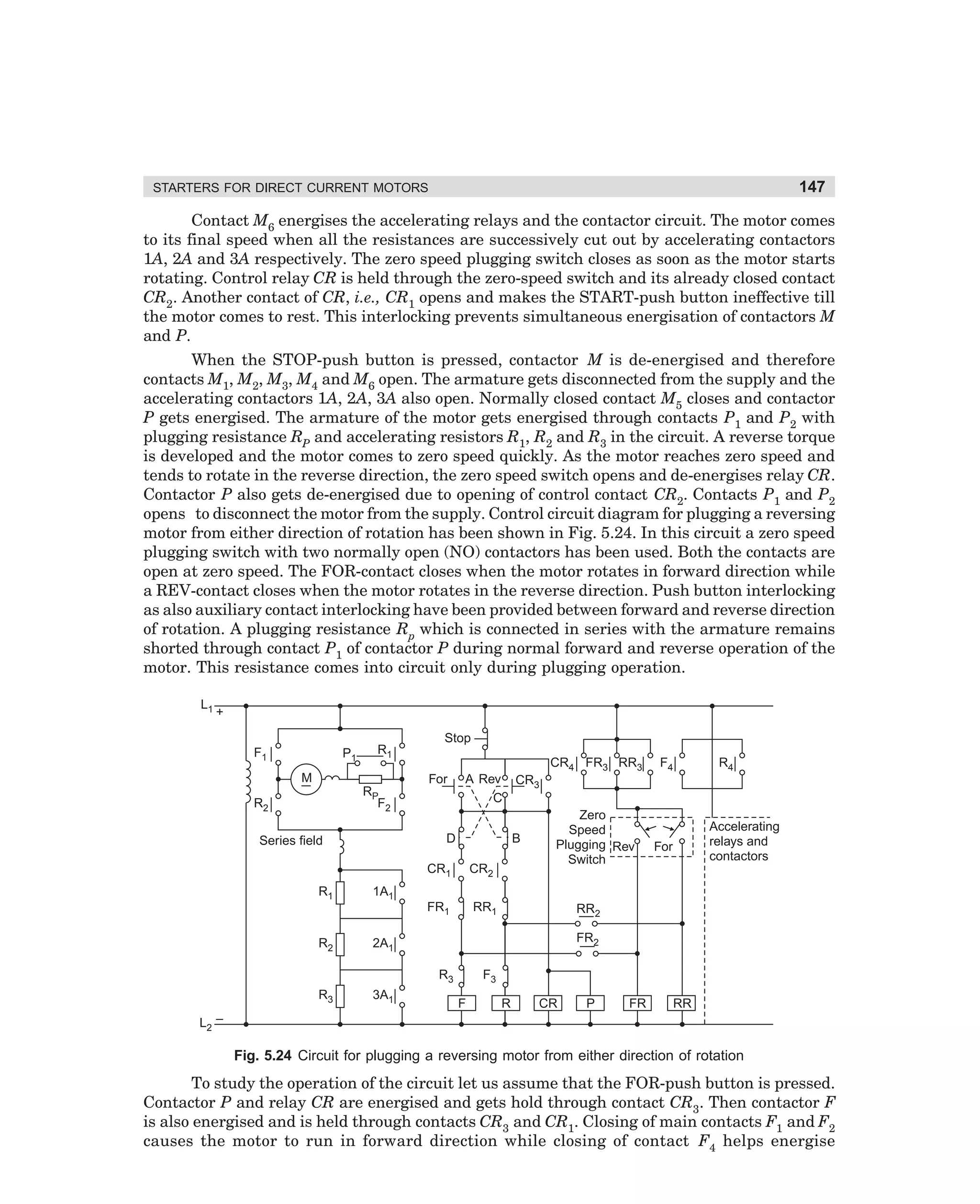
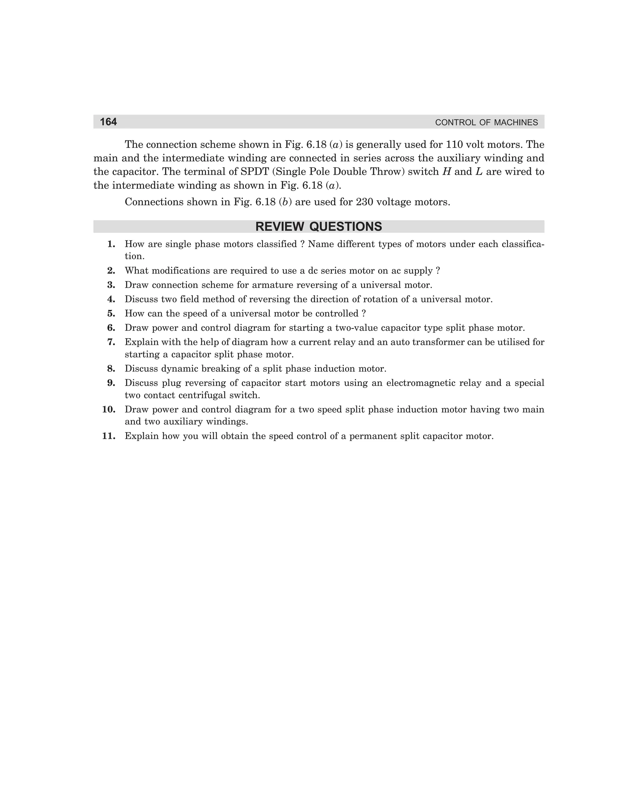
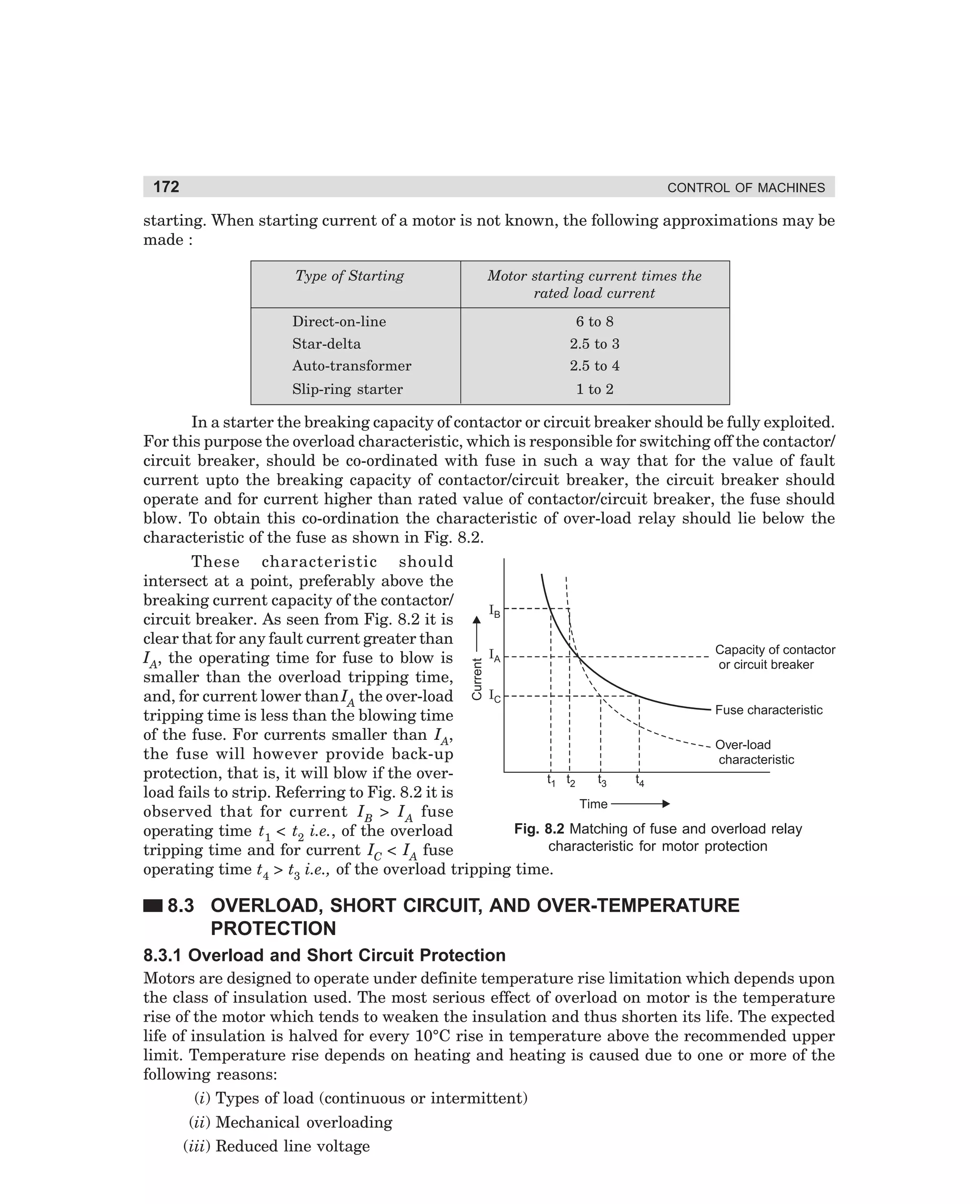
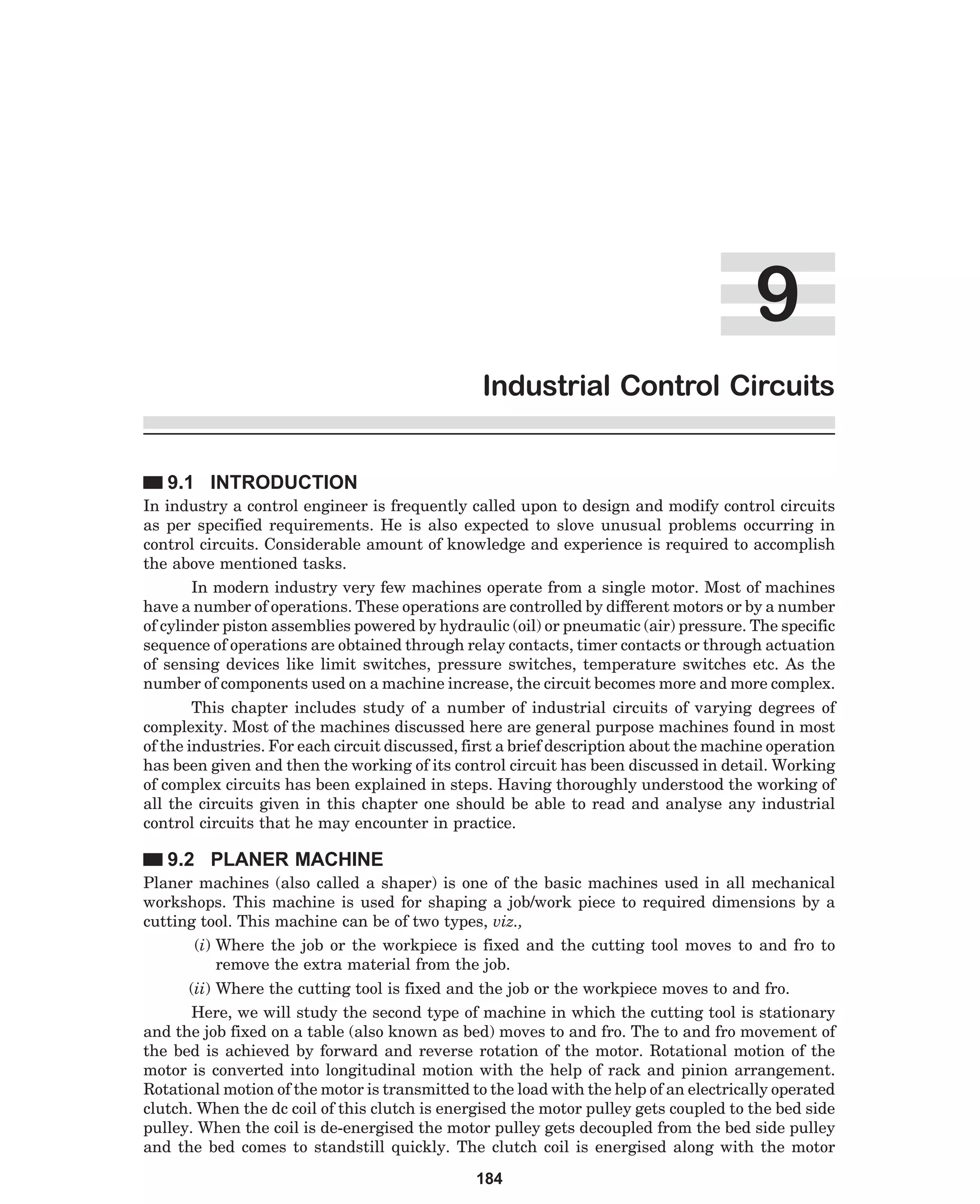
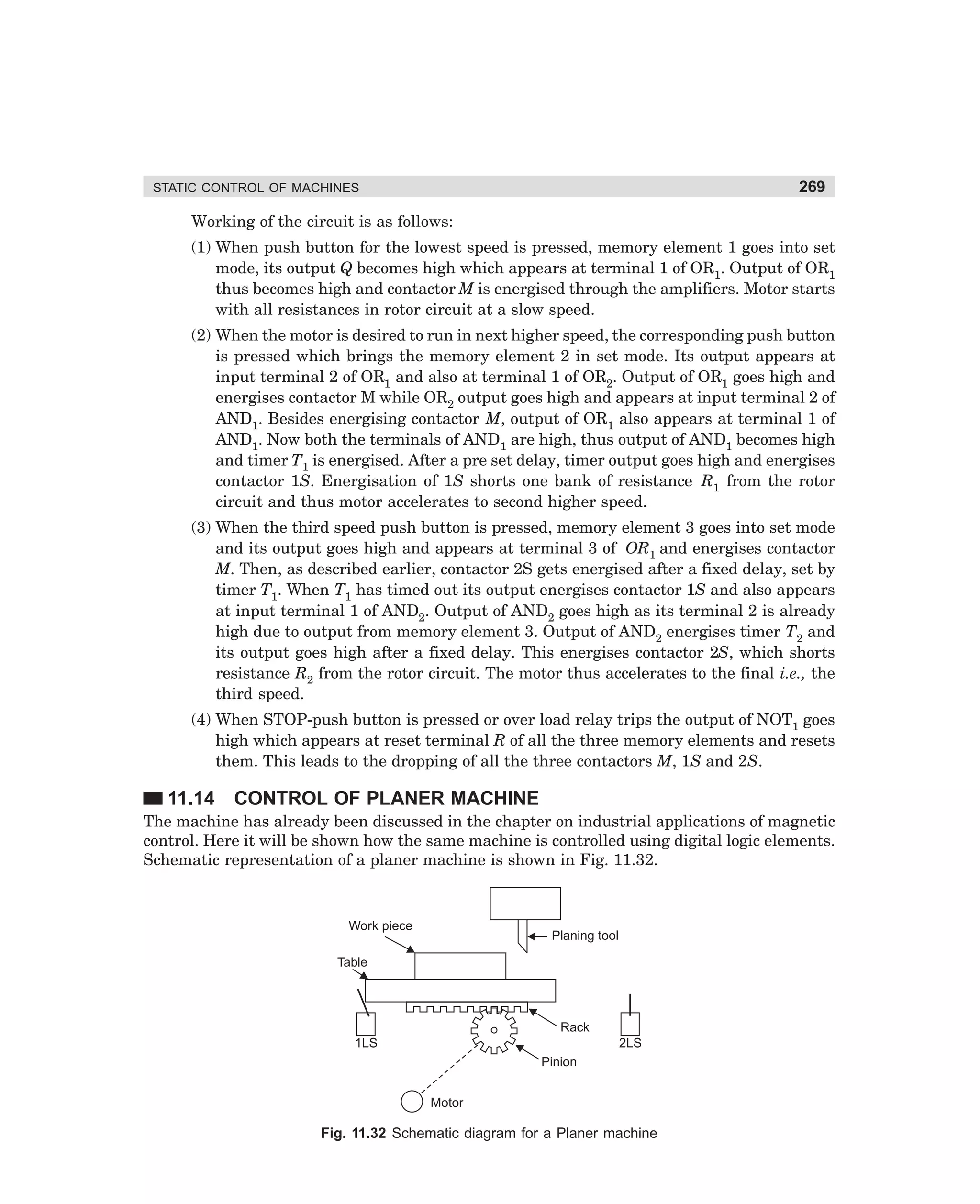
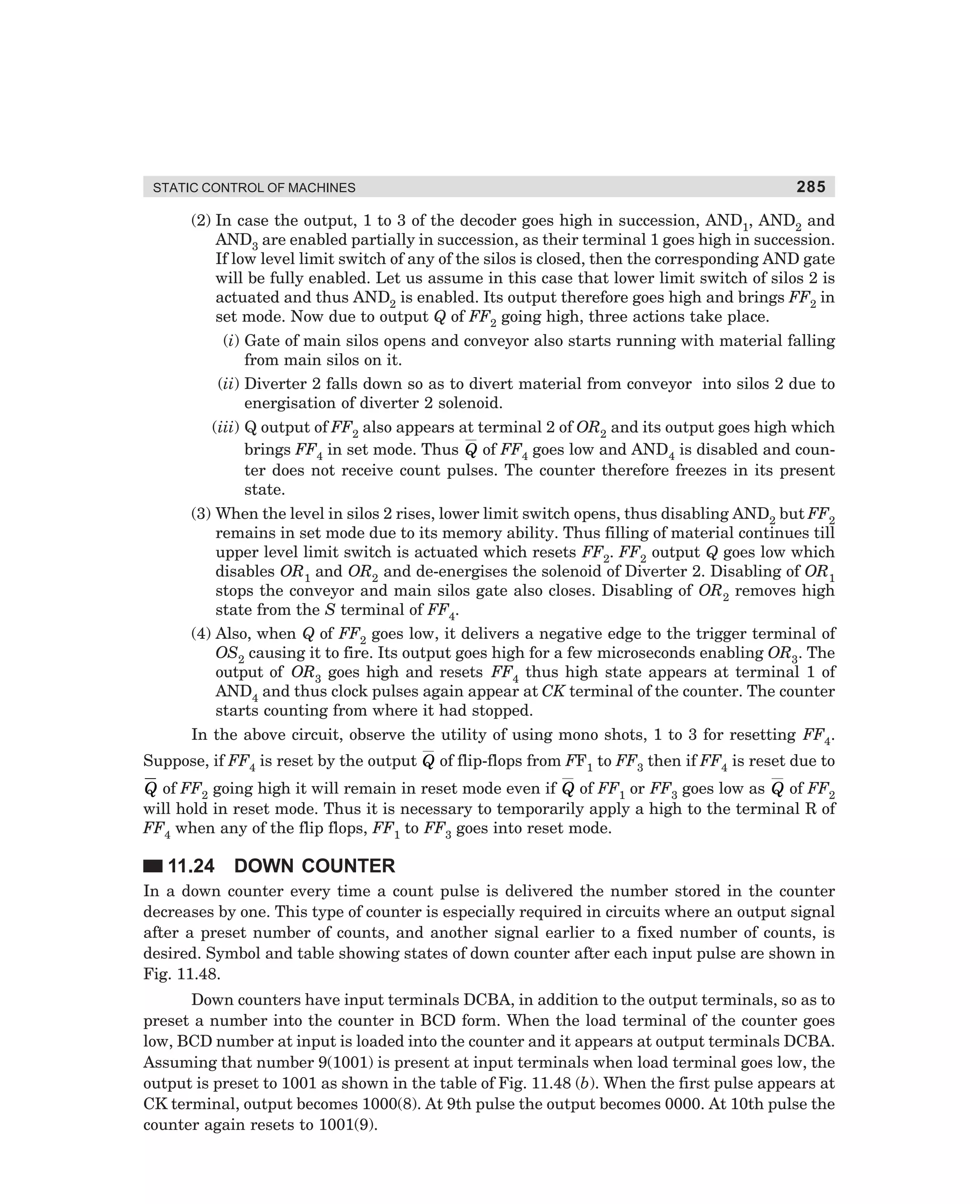
CR2
P
D1
S1
M1
OFF
B1
ON
CR1
D2
CR
N
S
M
Control on
Star
contactor
Main
contactor
S2
A1
A
Timer
T
B
D
Transition
contactor
Timer
Delta
contactor
Fig. 3.31 Control circuit for closed circuit transition automatic star-delta starter
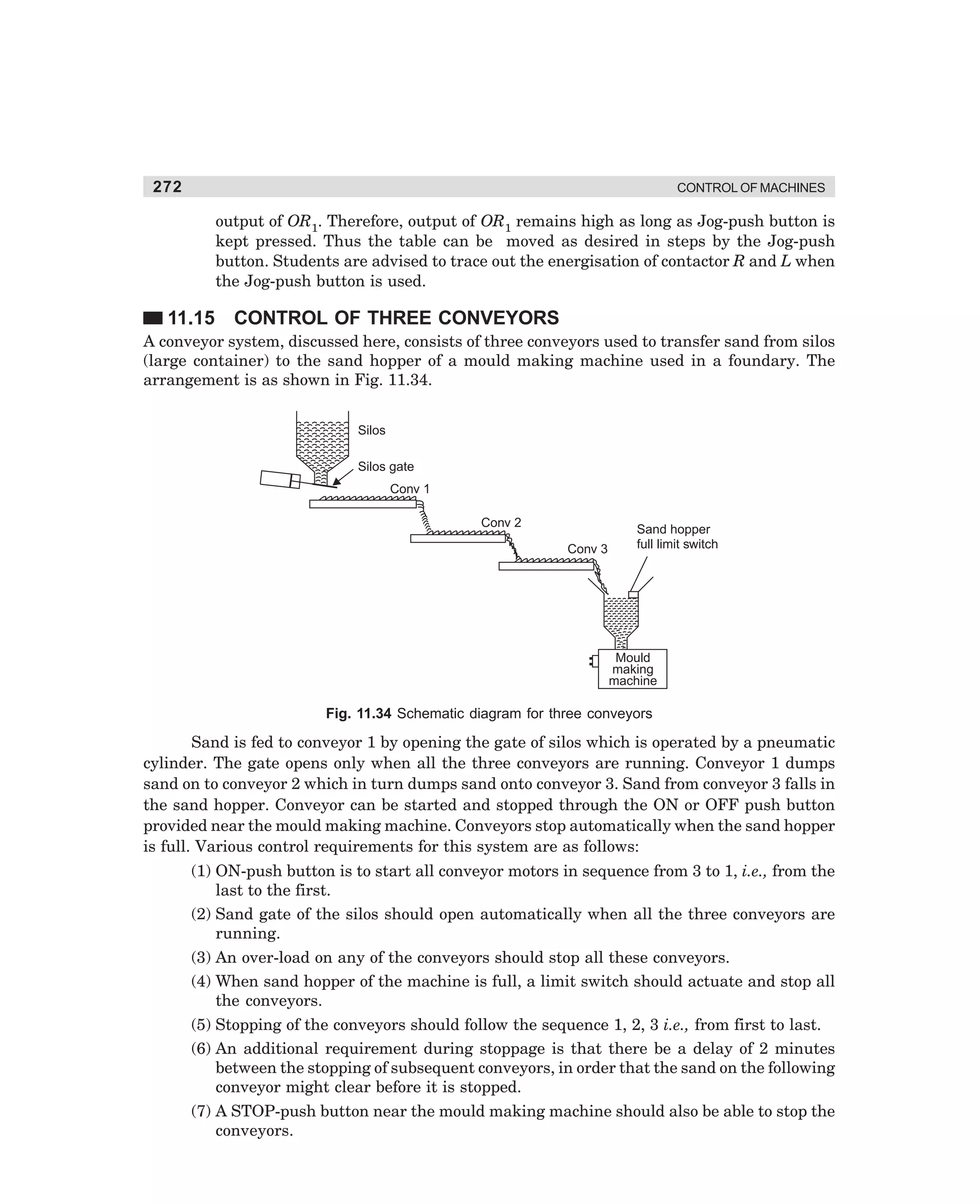
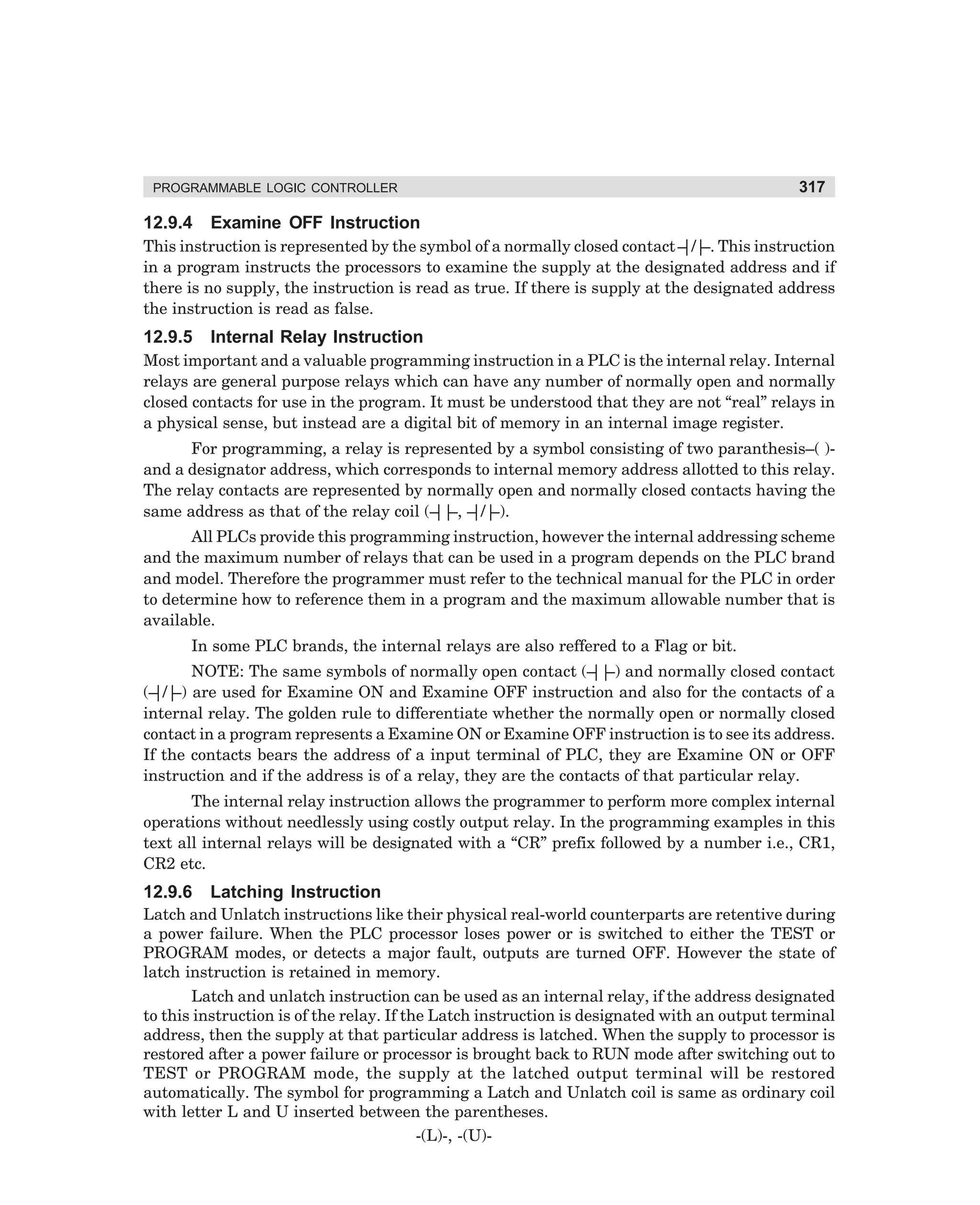
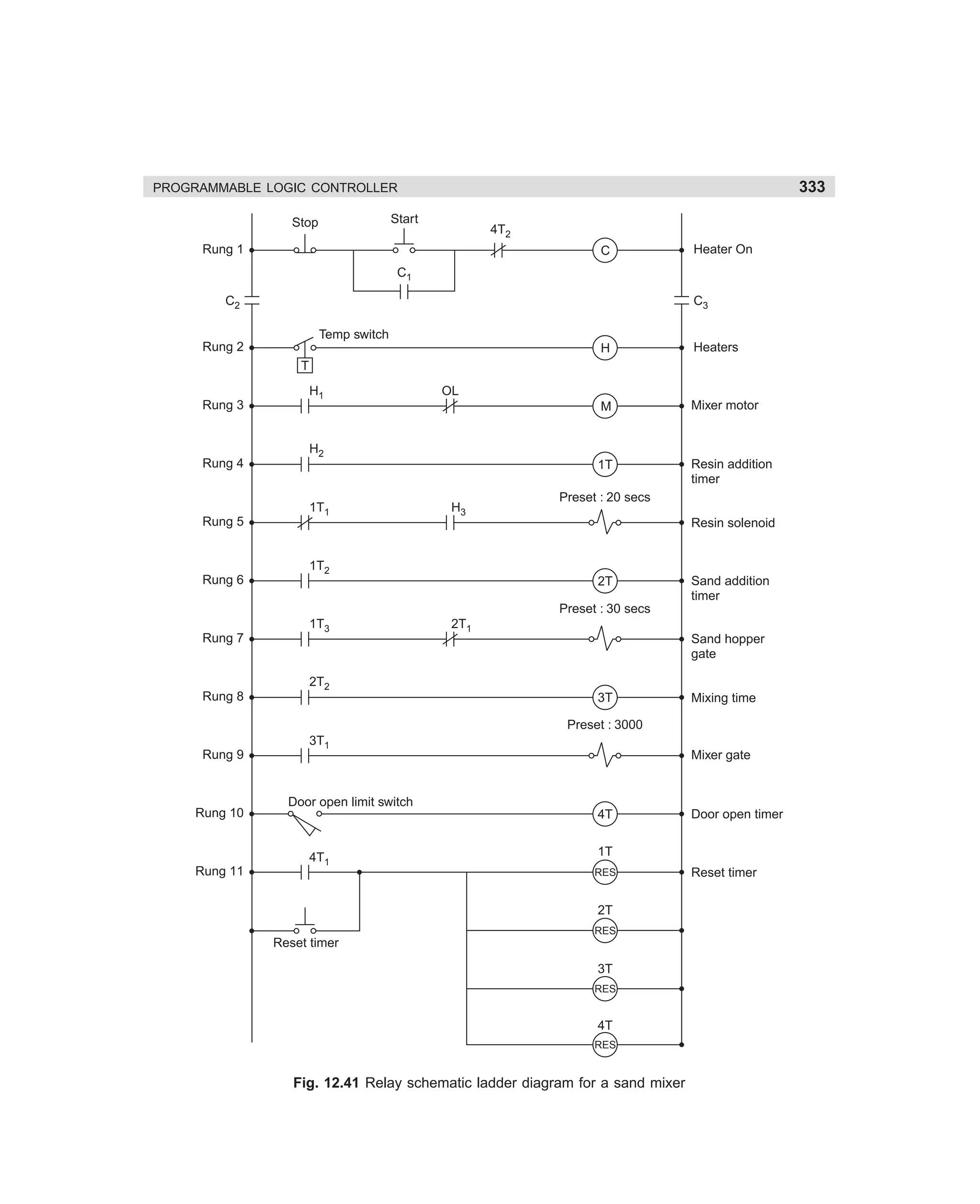
3.8 STARTERS FOR MULTI-SPEED MOTORS
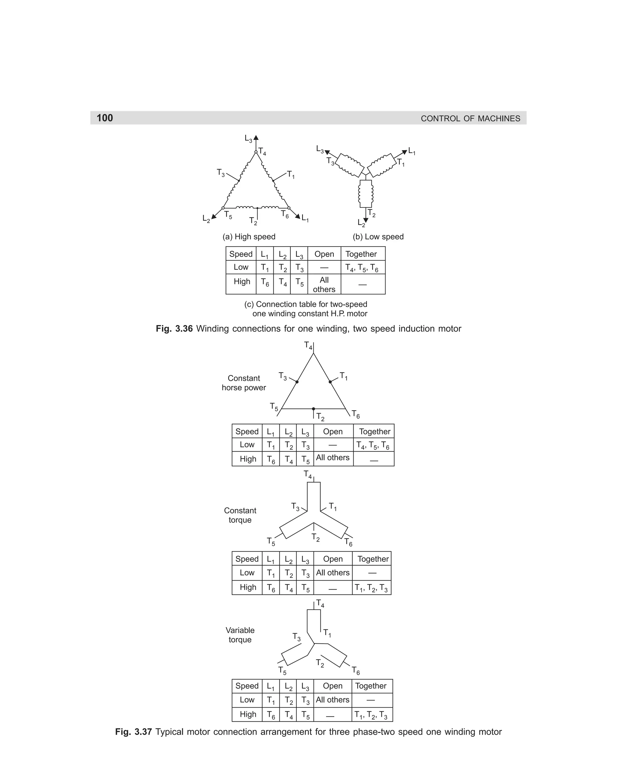
A squirrel cage motor is basically a constant speed motor, its speed being determined by the
line frequency and the number of poles of the stator winding. Such motors, however, can be
designed to have different speed by:
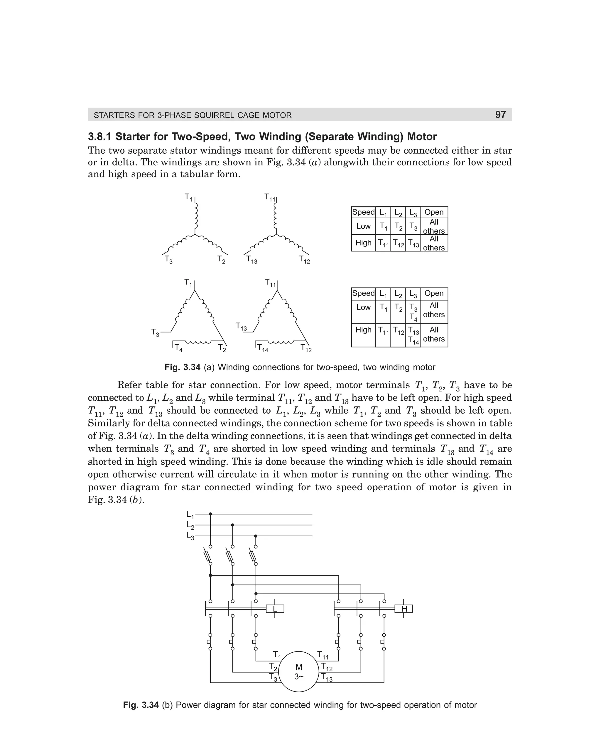
(i) having two separate stator windings wound for different number of poles;
(ii) having a consequent pole winding which can be reconnected to have two speeds. In
this type the choice of number of poles is restricted to a two-to-one ratio. For example, a consequent pole winding can be wound for four and eight poles, eight and
sixteen poles, and so on. Fig. 3.32 shows how poles are doubled by reconnection of
windings.
Fig. 3.32 The number of poles are doubled by reversing current through half
a phase (connection shown for one phase only)
dharm
d:N-MachMac3-2.pm5
95](https://image.slidesharecdn.com/controlofmachines-130110181054-phpapp01-140107230436-phpapp02/75/Controlofmachines-130110181054-phpapp01-112-2048.jpg)
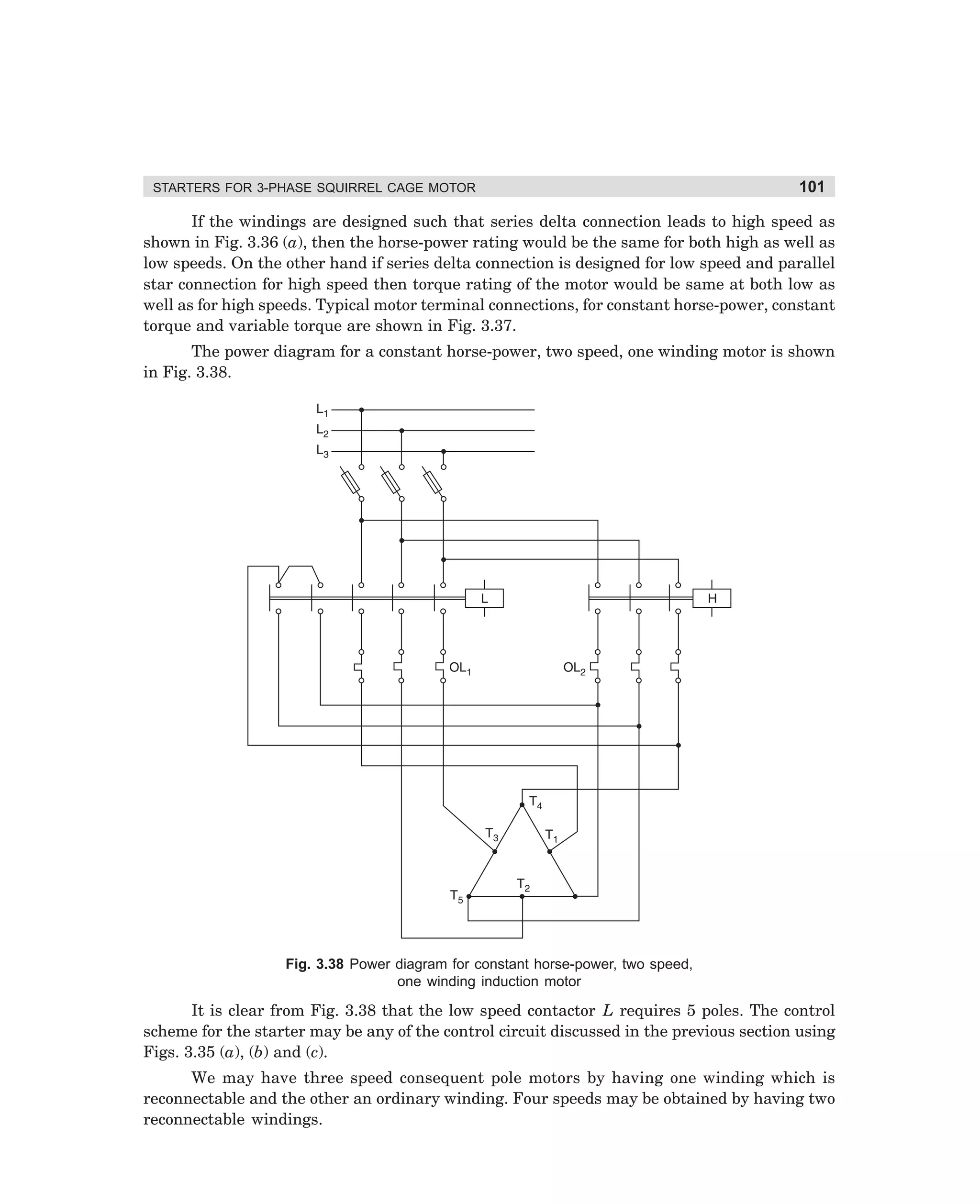
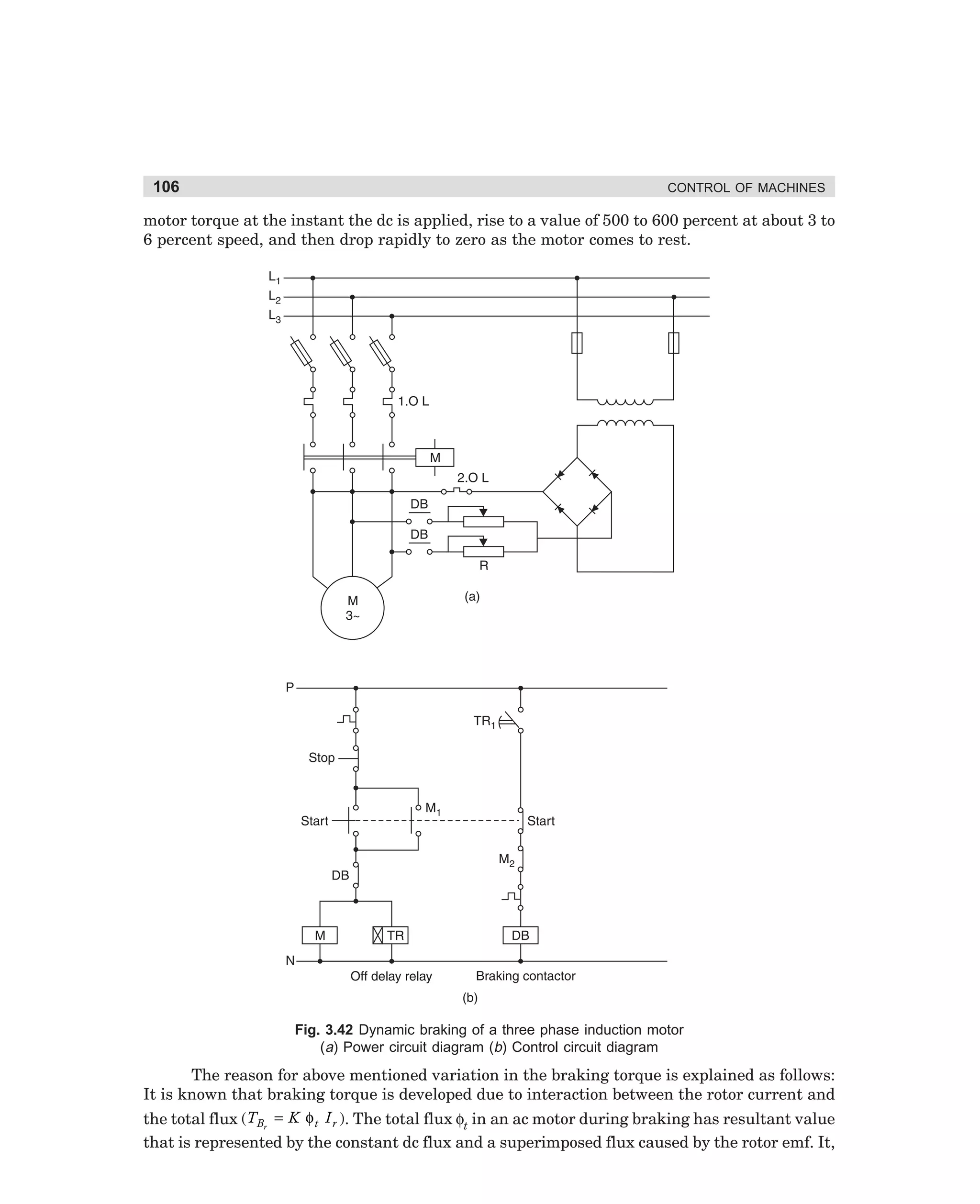
![STARTERS FOR 3-PHASE SQUIRREL CAGE MOTOR
ways:
105
Direct current can be supplied to the 3-phase windings in either of the following two
(1) A pair of stator terminals T1 and T2 connected across the dc source and the third
terminal T3 is left open. The same current would pass through the two windings,
they being in series.
(2) In this method two winding terminals, say, T2 and T3, are joined together and supply
is given between this junction and the third terminal T1. This is more popular arrangement as it develops less heating for a given braking torque. This connection
arrangement is shown in Fig. 3.41.
Fig. 3.41 Stator winding connections for dynamic braking
The power diagram and control diagram for dynamic braking of a squirrel cage induction
motor is shown in Fig. 3.42 (a) and (b). It can be seen from the power diagram that dc current
to the motor stator is controlled by a variable resistance R.
Contactor DB [see Fig. 3.42 (b)] has been used to switch on dc supply to the motor
terminals during braking. In the control circuit an OFF-delay timer has been used for setting
the time for which dc supply is to be given for braking. In an OFF-delay timer, the contact
operates after some time from the instant of switching off of the relay coil. In the circuit NC
contact of the START-push button has been used in series with the coil of contactor DB for
interlocking.
This interlocking is to avoid simultaneous energisation of contactor M and DB and thereby
mixing of ac and dc supply. The working of the control circuit is as follows: When the STARTpush button is pressed, contactor M gets energised and is held through its contact M1. OFFdelay time TR also gets energised, its delayed contact TR1 closes immediately, and keeps the
circuit ready for dynamic breaking. When the motor is to be stopped, on pressing the STOPpush button contactor M and timer TR get de-energised. Contactor DB gets energised through
delayed contact TR1 of the timer and the closed contact M2. Closing of contactor DB applies dc
supply to the stator terminals. When the OFF-delay timer operates, its contact opens and deenergises contactor DB.
In this type of Dynamic braking, the braking torque varies considerably over the braking
period. Depending upon the magnitude of dc excitation, braking torque may be 50% of rated
dharm
d:N-MachMac3-2.pm5
105](https://image.slidesharecdn.com/controlofmachines-130110181054-phpapp01-140107230436-phpapp02/75/Controlofmachines-130110181054-phpapp01-122-2048.jpg)
![114
CONTROL OF MACHINES
Fig. 4.5 Manual face-plate starter (a) Power diagram (b) Schematic control diagram
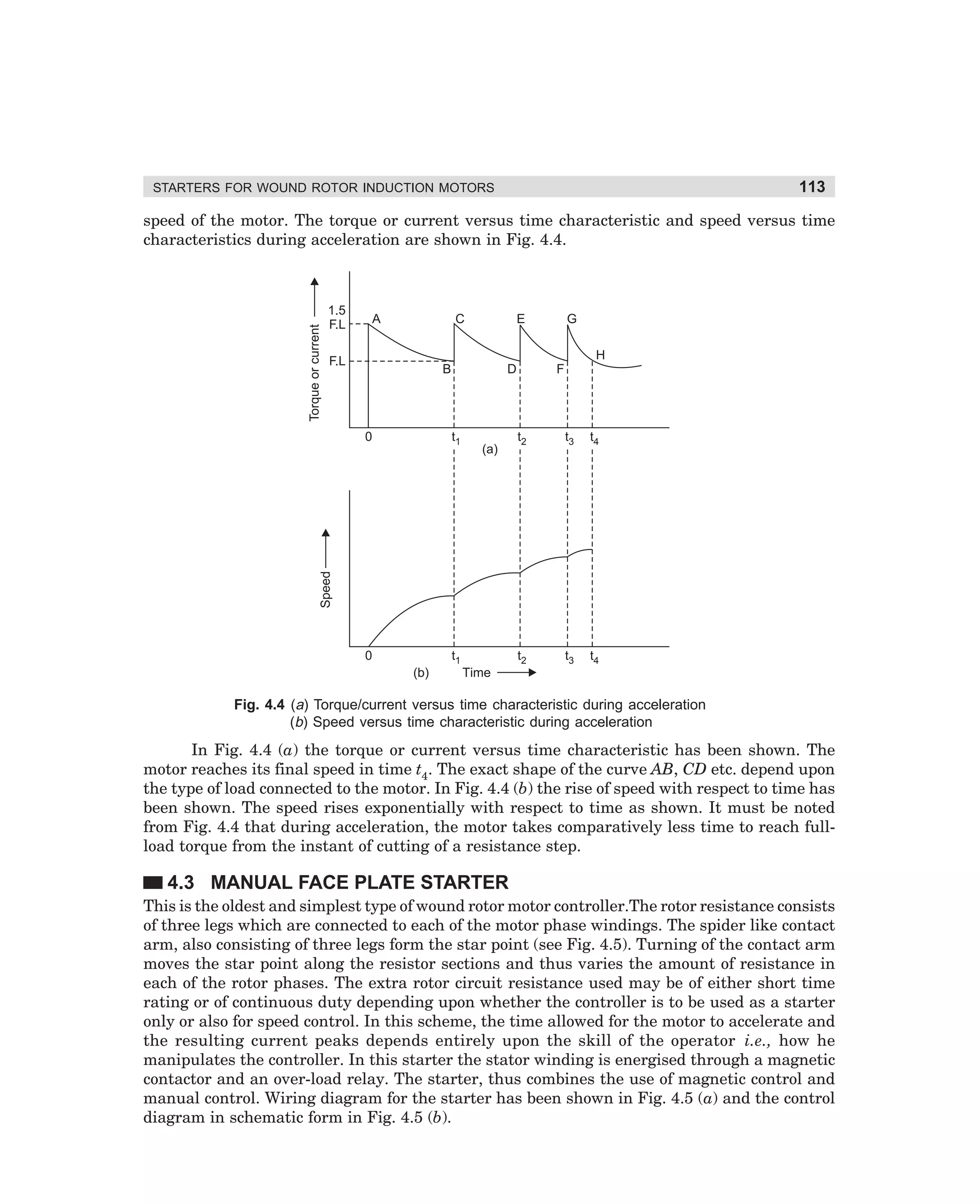
Interlocking provided in the starter permits the motor to be started only when whole of
the controller resistance is in the circuit. This is obtained by using an auxiliary contact of
controller in series with the ON-push button. When controller handle is in the position shown
in Fig. 4.5 (a), the whole of controller resistance is in the rotor circuit. At this position the
handle keeps the auxiliary contact closed. When the handle is moved in anti-clockwise direction,
this contact opens. The operation of starter is explained as follows : When the ON-push button
is pressed contactor M will get energised if the auxiliary contact ‘a’ of controller, which is in
series with ON-push button, is closed i.e., if the whole of the controller resistance is in the
rotor circuit. The contactor M remains energised through its auxiliary contact M1 bypassing
the auxiliary contact interlocking [(see Fig. 4.5 (b)]. With the closing of contactor M, the motor
starts with full controller resistance in the circuit. The controller resistance is now gradually
cut out from the three rotor phases by moving the handle in anti-clockwise direction from step
1 to step 4. At step 4, the whole of the resistance is cut out and the motor runs at its final speed.
The time for acceleration depends entirely upon the judgement of the operator. The motor
stops when OFF-push button is pressed or the overload trips causing de-energisation of contactor
M. When the motor is to be started again the controller handle has to be brought to initial
position again as shown in Fig. 4.5 (a). Face plate starters are simple in construction and have
low cost but they lack sturdiness and are unsatisfactory for frequent operations. This
disadvantage is overcome by drun switches. The rotary sliding contact fingers are mounted on
a drum shaft and they make contact with stationary contact fingers when the drum shaft is
rotated. The springs of the moving contacts maintain better and more uniform contact force.
In a drum switch controller the magnetic contactor for the starter can also be eliminated by
having the main contacts on the drum controller itself. Drum switches may be designed for
reversing the motor also. Drum switches, are however, often used in conjunction with a magnetic
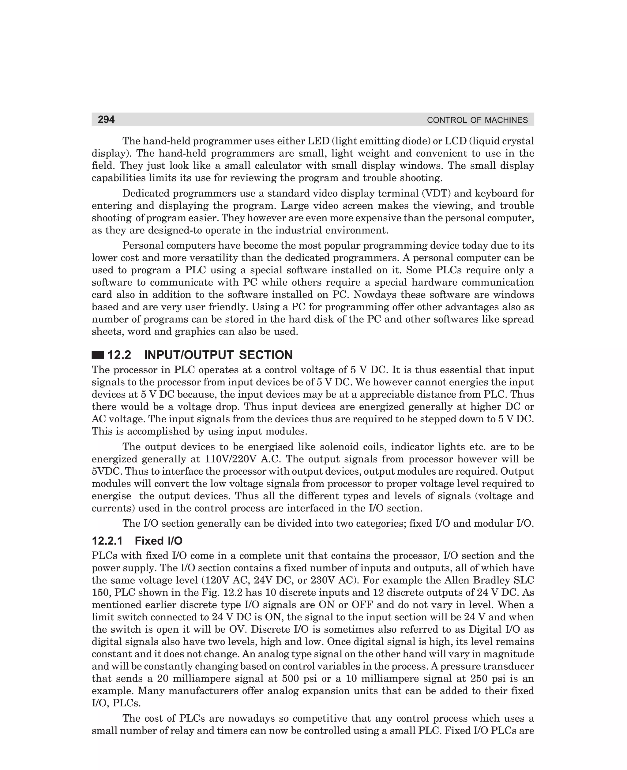
contactor which facilitates inclusion of overload protection or any other pilot device for the
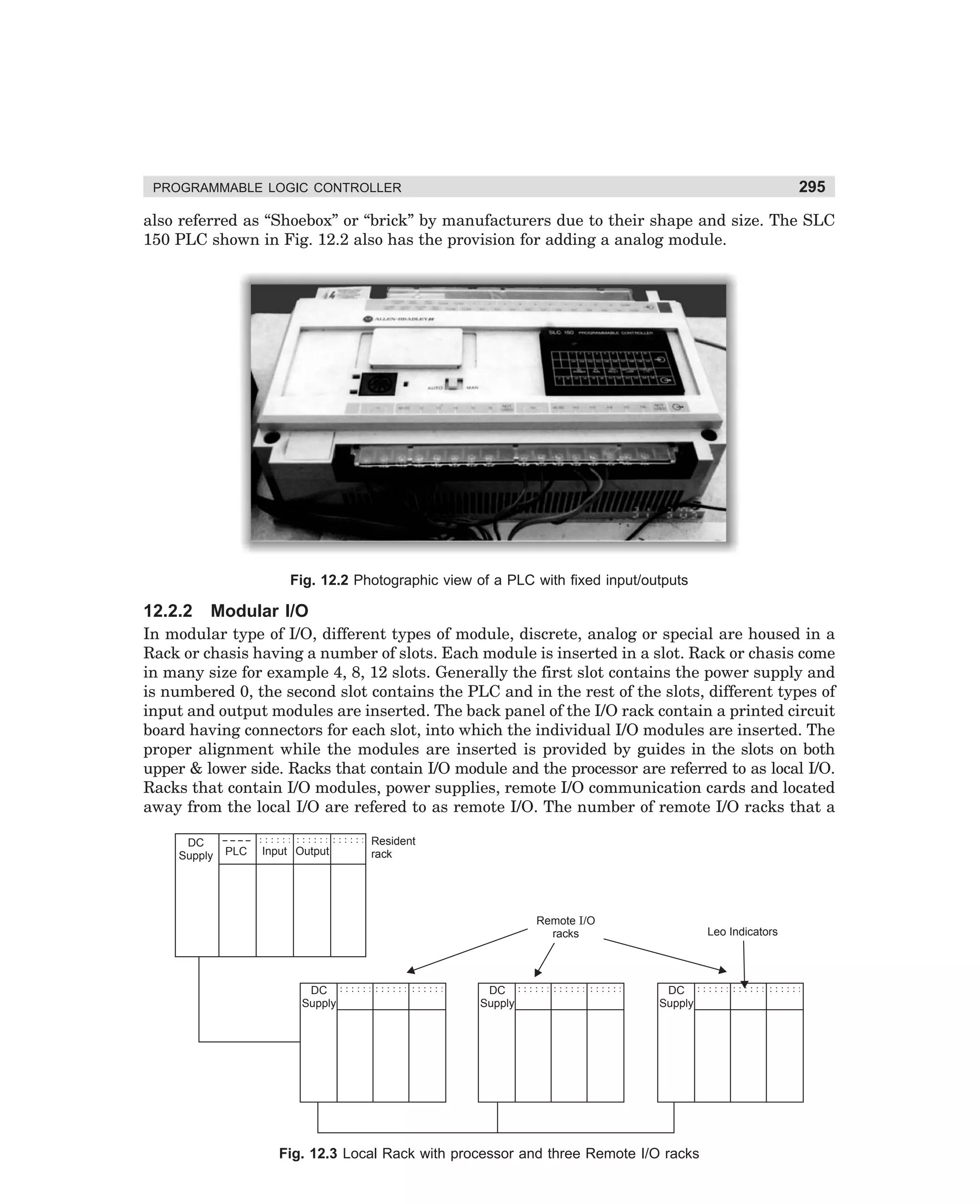
control of the motor.
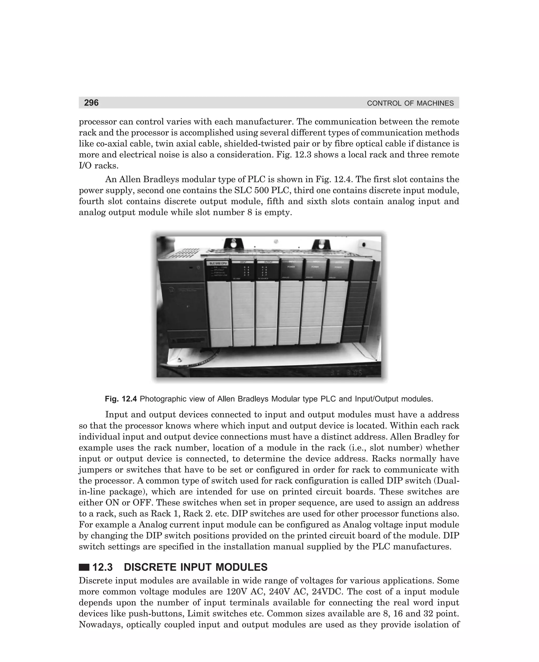
dharm
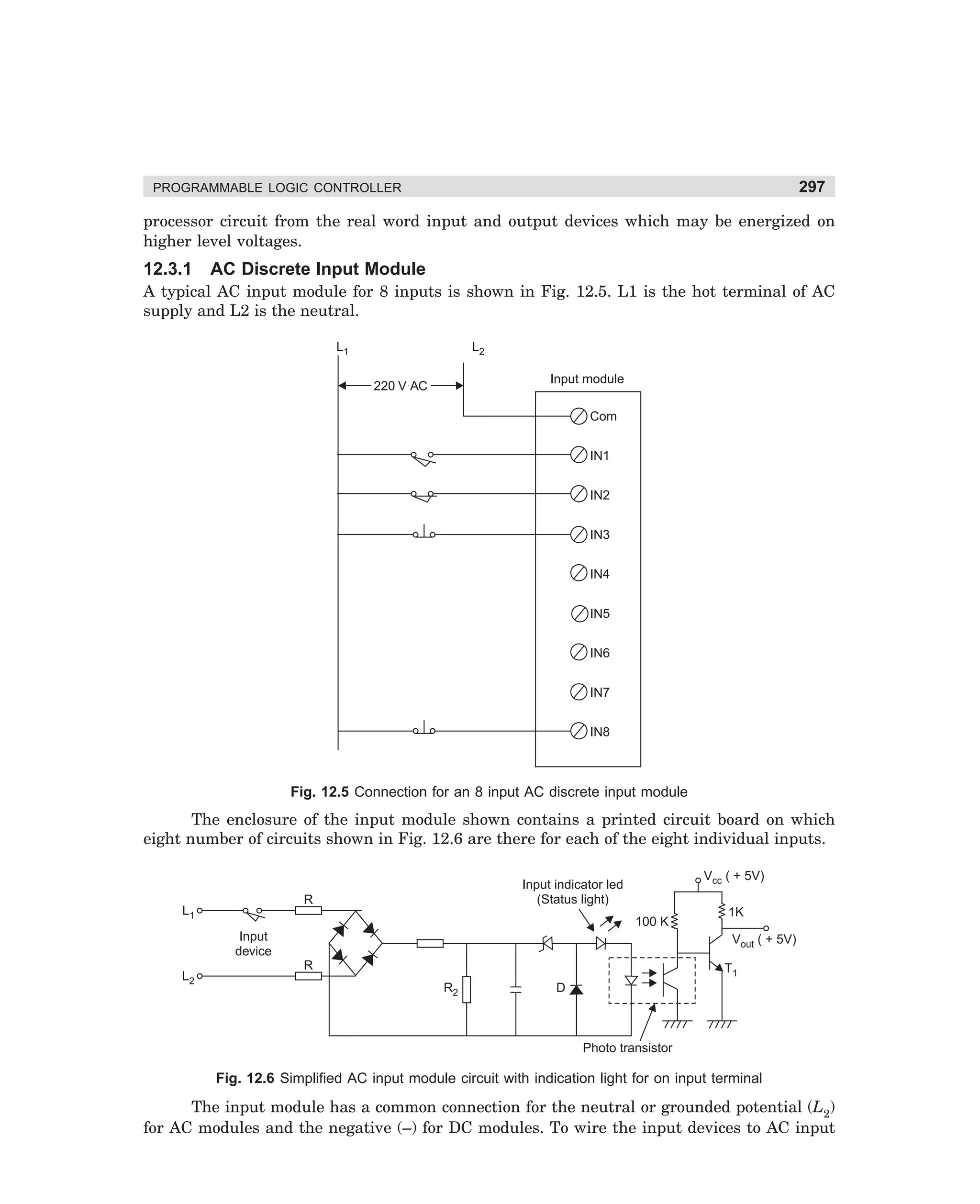
d:N-MachMac4-1.pm5
114](https://image.slidesharecdn.com/controlofmachines-130110181054-phpapp01-140107230436-phpapp02/75/Controlofmachines-130110181054-phpapp01-131-2048.jpg)
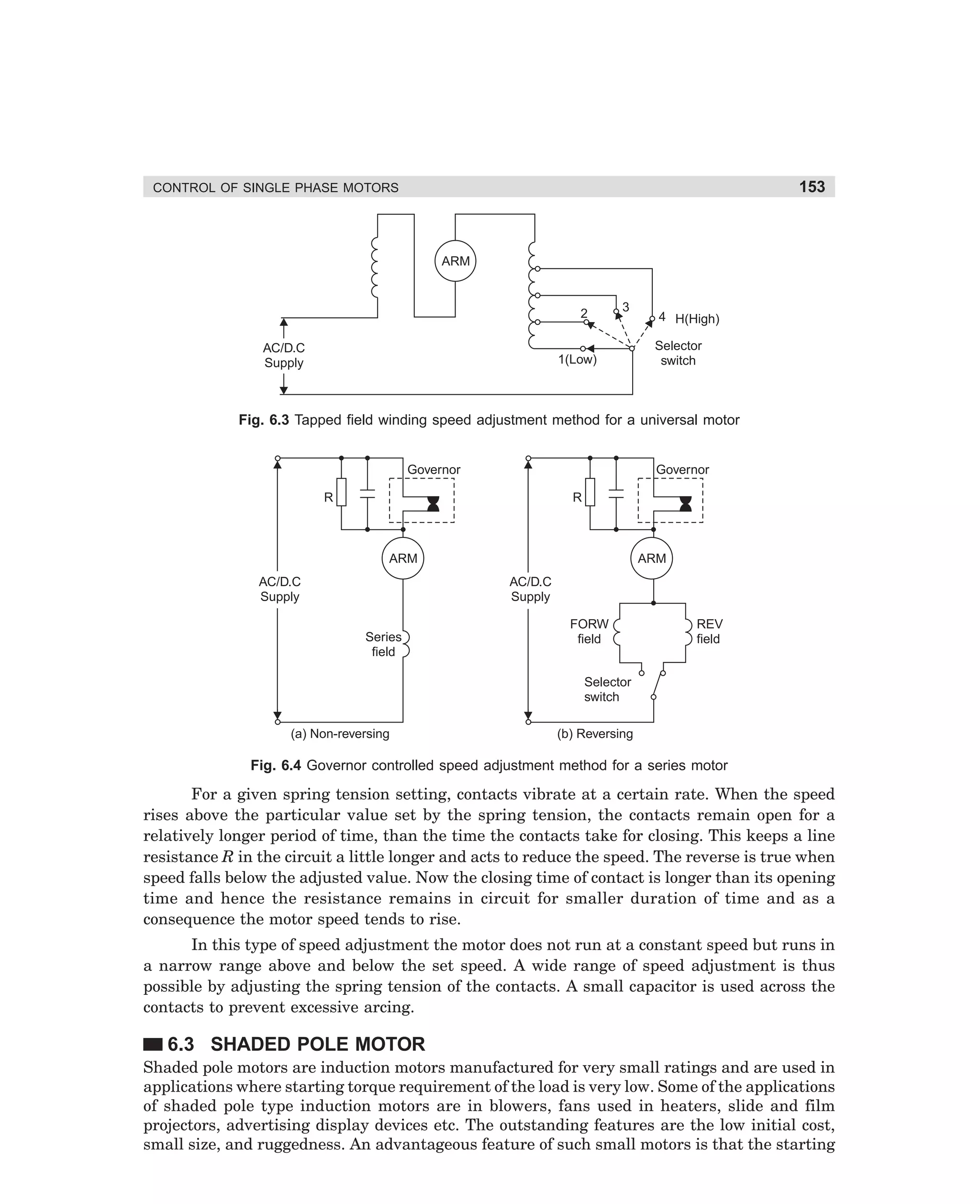
![154
CONTROL OF MACHINES
current is only slightly higher than the full-load current and therefore the stalled motor condition
is not harmful to the motor windings.
Cross sectional view of a shaded pole type motor has been shown in Fig. 6.5. The stator
shown are projected type. Short circuited coils known as shading coils (rings) are fixed on one
portion of each pole. A pole on which a shading ring is fixed is called a shaded pole. Shading
coil can be of thick single turn in the form of a ring or have a number of short circuited turns.
The rotor is of conventional squirrel cage type.
Unshaded
portion of
the pole
Shaded
portion
Shading V~
ring
V~
Squirrel
cage rotor
(a)
(b)
Fig. 6.5 Shaded pole type induction motors of different design
The magnetic field created by the field ampere-turns of a shaded pole motor varies in
magnetic strength and merely shifts from one side of the salient pole to the other side for every
half cycle of the supply voltage. The direction of rotation of shaded pole motors with a single
set of field windings and shading coils can not be reversed. The motor would always rotate in
a direction from the unshaded part to the shaded part of the pole. For enabling reversal of
direction of rotation, the construction of the stator must be changed to include :
(1) Two sets of shading coils that are normally open circuited and occupy different positions with respect to the main field winding.
(2) Two main windings that occupy different positions with respect to the shading coils.
(3) A special distributed continuous winding that is placed in a slotted stator core and is
tapped at appropriate points with respect to the shading coils.
Fig. 6.6 (a) shows shading coils placed on both sides of each of the salient poles. With the
help of short-circuiting switch either set of shading coils can be made effective. The coils which
are short circuited determine the direction of rotation. When the selector switch [Fig. 6.6 (a)] is
in position F, shaded coils A and A′ are shorted while shaded coils B and B′ are open. When the
switch position is changed, coils B and B′ are shorted while A and A′ become open.
In Fig. 6.6 (b) two distributed windings are placed 90° electrical degrees apart with
respect to each other and 45° electrical degrees from the shading coils in a slotted stator. In
Fig. 6.6 (c) a continuous distributed winding is used and tapped at 90° electrical degrees.
Leads from these tappings are connected to a DPDT switch. With alternate position of DPDT
switch, the main winding can have either positive or negative 90° electrical degrees relationship
with respect to the shading coils. In one case the rotor will turn clockwise and in the other case
the rotor will turn counter clockwise.
dharm
d:N-MachMac6-1.pm5
154](https://image.slidesharecdn.com/controlofmachines-130110181054-phpapp01-140107230436-phpapp02/75/Controlofmachines-130110181054-phpapp01-171-2048.jpg)


This document provides information about the publisher, New Age International Pvt. Ltd. It includes the publisher's contact information and website. It also provides copyright information for the book being summarized, indicating it was published in 2006 and that all rights are reserved by New Age International Pvt. Ltd. The document does not contain any other substantive information.


![Electric drives [ned mohan 2001 (scanned) 470pág]](https://cdn.slidesharecdn.com/ss_thumbnails/electricdrivesnedmohan2001-scanned470pg-121224050928-phpapp01-thumbnail.jpg?width=640&height=640&fit=bounds)


