Downloaded 172 times


![electromechanical relays is considered "de-energized.Ladder logic has contacts that make or
break circuits to control coils. Each coil or contact corresponds to the status of a single bit in
the programmable controller's memory. Unlike electromechanical relays, a ladder program
can refer any number of times to the status of a single bit, equivalent to a relay with an
indefinitely large number of contacts.
So-called "contacts" may refer to physical ("hard") inputs to the programmable controller
from physical devices such as pushbuttons and limit switches via an integrated or external
input module, or may represent the status of internal storage bits which may be generated
elsewhere in the program.
Each rung of ladder language typically has one coil at the far right. Some manufacturers may
allow more than one output coil on a rung.
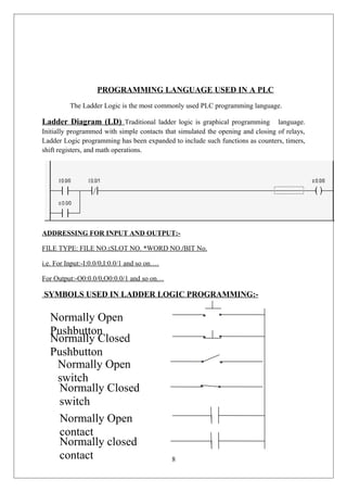
--( )-- a regular coil, energized whenever its rung is closed
--()-- a "not" coil, energized whenever its rung is open
--[ ]-- A regular contact, closed whenever its corresponding coil is energized
--[]-- A "not" contact, open whenever its corresponding coil is energized
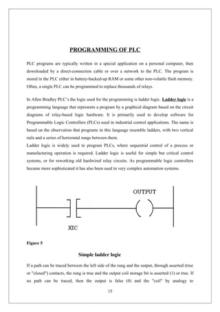
The "coil" (output of a rung) may represent a physical output which operates some device
connected to the programmable controller, or may represent an internal storage bit for use els
Example-:-
------[ ]--------------[ ]----------------O---
Key Switch 1 Key Switch 2 Motor
“This is a logical AND.”
COMMUNICATION OF PLC WITH PC:-
To make communication of PLC with PC following steps are noted down:
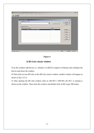
1) Connect PC and PLC via RS232 comport or Ethernet.
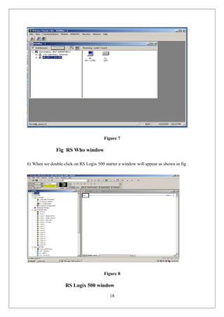
2) Then click on RS Linx icon, a window will appear as shown in fig below
16](https://image.slidesharecdn.com/sixweektrainingreport-151113182012-lva1-app6892/85/Training-Report-on-PLC-SCADA-16-320.jpg)
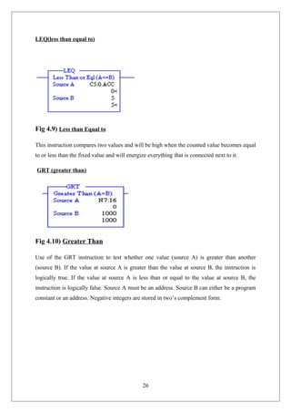
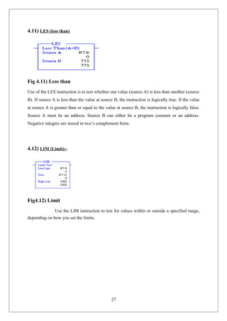
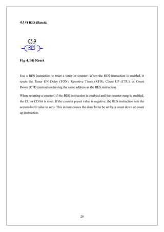


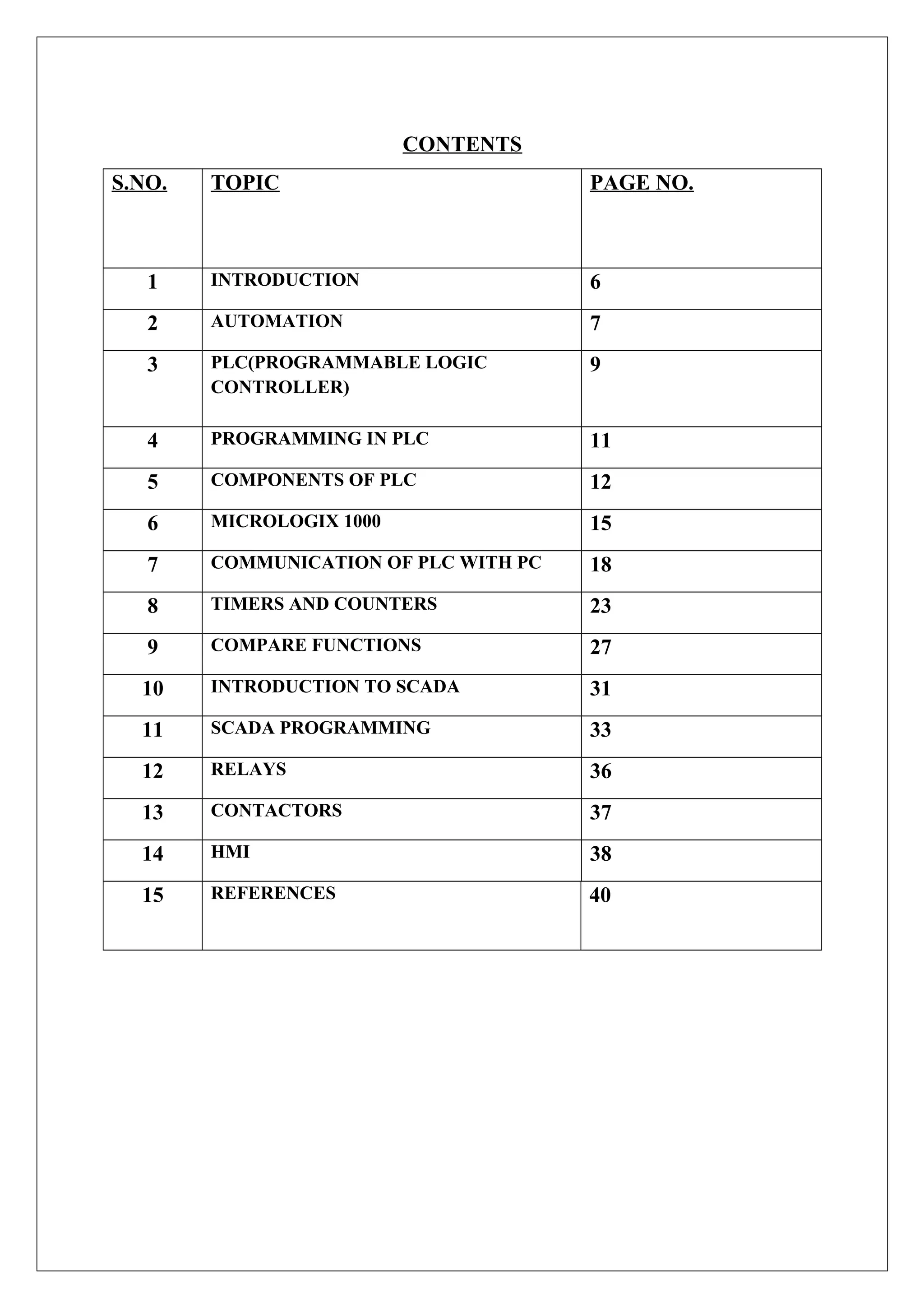
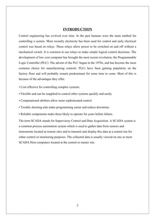
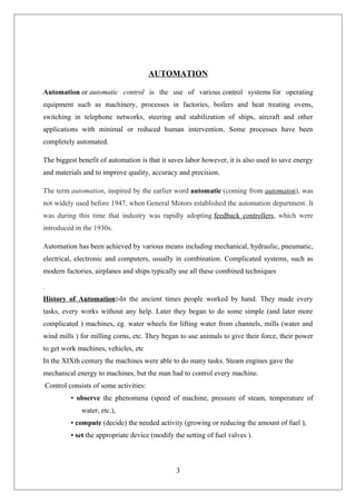
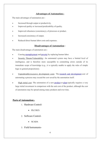
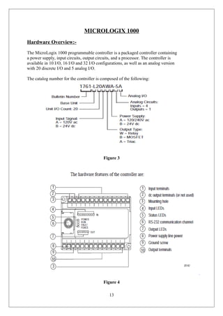
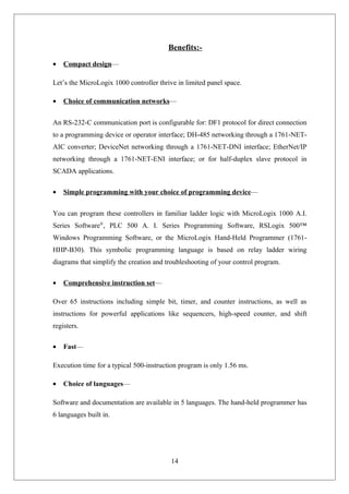
The document provides an overview of automation and control engineering, focusing on the development and functionality of Programmable Logic Controllers (PLCs) and SCADA systems. It covers the evolution of control methods, the advantages and disadvantages of automation, and details various components of PLCs, including their programming using ladder logic. Additionally, the Micrologix 1000 and its respective benefits and configurations are discussed, outlining the importance of PLCs in enhancing industrial automation.