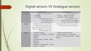
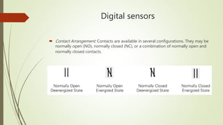
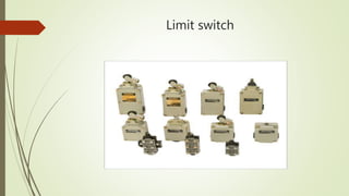
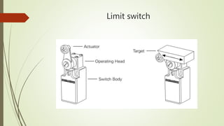
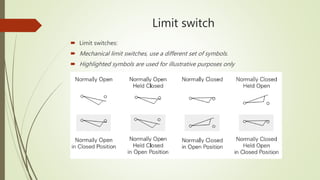
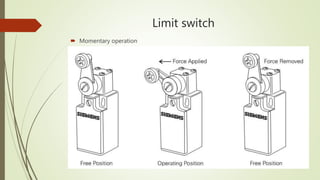
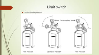
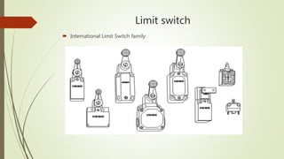
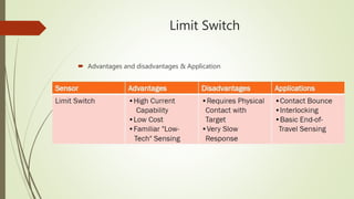
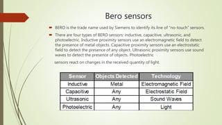
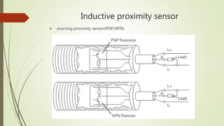
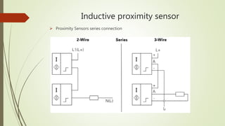
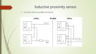
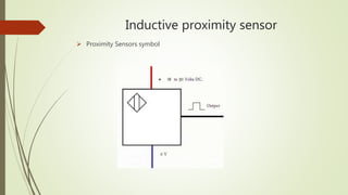
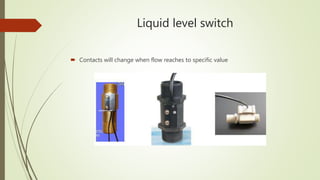
sensors
BY: Mahmoud Hussein
sensors
 There are different types of sensors for different purposes
 To sense different goals in the shape and method of work and raw Material in
terms of being a metal or dielectric and at different distances.
 and also to measure various physical quantities such as pressure and temperature
and distance
 Specification
 There are Different theory of the work of the various sensors and function and the
type of the O/P signal and also the method of Connections and the Source voltage
 Then, sensors can be divided into several divisions depends on set of properties
sensors
 Optical sensors : (Through beam – Retro reflective – Diffuse )
 Proximity sensors: ( Inductive – Inductive magnetic – Capacitive)
 Switches : (Reed SW – Pressure SW – liquid level SW – Flow SW – Limit SW )
 Physical quantity sensors : ( Pressure sensor – Temperature sensor – Flow sensor
–weight sensor)
 Sensors can be classified according to
 Feed voltage (24VDC-220VAC)
 o/p signal (digital /analogue)
Digital sensors VS Analogue sensors
Digital sensors
 Contact Arrangement: Contacts are available in several configurations. They may be
normally open (NO), normally closed (NC), or a combination of normally open and
normally closed contacts.
Limit switch
Limit switch
Limit switch
 Limit switches:
 Mechanical limit switches, use a different set of symbols.
 Highlighted symbols are used for illustrative purposes only
Limit switch
 Momentary operation
Limit switch
 Maintained operation
Limit switch
 International Limit Switch
Limit switch
 International Limit Switch family
Interlock switches
Limit Switch
 Advantages and disadvantages & Application
Inductive proximity sensor
Bero sensors
 BERO is the trade name used by Siemens to identify its line of “no-touch” sensors.
 There are four types of BERO sensors: inductive, capacitive, ultrasonic, and
photoelectric. Inductive proximity sensors use an electromagnetic field to detect
the presence of metal objects. Capacitive proximity sensors use an electrostatic
field to detect the presence of any object. Ultrasonic proximity sensors use sound
waves to detect the presence of objects. Photoelectric
sensors react on changes in the received quantity of light.
Inductive proximity sensor
 used to detect the presence of a conductive metal object.
 they detect the presence of an object without coming into physical contact with it.
Inductive proximity sensor
 Inductive proximity sensors are available in a variety of sizes and configurations to
meet
Inductive proximity sensor
 inductive proximity sensors are operated using (ECKO) principle.
 (ECKO) principle : Eddy Current Killed Oscillator
 This type of sensor consists of four elements: coil, oscillator, trigger circuit, output.
 The oscillator is an inductive capacitive tuned circuit that creates a radio frequency.
 The electromagnetic field produced by the oscillator is emitted from the coil away
from the face of the sensor
Inductive proximity sensor
 The circuit has just enough feedback from the field to keep the oscillator going.
 When a metal target enters the field, eddy currents circulate within the target.
 This causes a load on the sensor, decreasing the amplitude of the electromagnetic field.
 As the target approaches the sensor the eddy currents increase, Increasing the load on
the oscillator and further decreasing the amplitude of the field.
 The trigger circuit monitors the oscillator’s amplitude
 At a predetermined level switches the output state of the sensor from its normal
condition (on or off).
 As the target moves away from the sensor, the oscillator’s amplitude increases.
 At a predetermined level the trigger switches the output state of the sensor back to its
normal condition
Inductive proximity sensor
 Proximity Sensors O/P Configuration.
Inductive proximity sensor
 sourcing proximity sensor(PNP,NPN)
Inductive proximity sensor
 sensor wiring number
Inductive proximity sensor
 Proximity Sensors series connection
Inductive proximity sensor
 Proximity Sensors parallel connection
Inductive proximity sensor
 Proximity Sensors symbol
Inductive proximity sensor
 Standard target
 A standard target is defined as having a flat, smooth surface, made of mild steel
that is 1 mm (0.04”) thick.
 If the target is larger than the standard target, the sensing range does not change
 However, if the target is smaller or irregular shaped the sensing distance (Sn)
decreases.
 The smaller the area of the target the closer it must be to the sensing face to be
detected.
Inductive proximity sensor
 Application
Capacitance proximity sensor
 Capacitive proximity sensors are similar to inductive proximity sensors.
 The main difference between the two types is that capacitive proximity sensors
produce an electrostatic field instead of an electromagnetic field.
 Capacitive proximity switches will sense metal as well as nonmetallic materials such
as paper, glass, liquids, and cloth
Capacitance proximity sensor
 Sensor is looking for a change in capacitance in the active field
 When an object nears the sensing surface it enters the electrostatic field of the
electrodes
 Changes the capacitance in an oscillator circuit.
 As a result, the oscillator begins oscillating. The trigger circuit reads the oscillator’s
amplitude
 when it reaches a specific level the output state of the sensor changes.
 As the target moves away from the sensor the oscillator’s amplitude decreases,
Switching the sensor output back to its original state.
 Detects any material denser than air (as long as there is enough of it) Can be
adjusted for sensitivity Can be affected by dusty environments
capacitance proximity sensor
 Proximity Sensors O/P Configuration.
capacitance proximity sensor
 Proximity Sensors O/P Configuration.
capacitance proximity sensor
application
 Sensor is adjusted so that it does not Detect the wall of the vessel
 Application Detecting Milk in Cartons Capacitive Sensor
 Application Controlling Fill level of solids in a bin Capacitive Sensor
 Detecting Presence of Can and Full
Optical sensors
 A photoelectric sensor is another type of position sensing device.
 Photoelectric sensors , use a modulated light beam that is either broken or
reflected by the target.
Optical sensors
 Thru-Beam Scan Techniques
Optical sensors
 Thru-Beam Scan Techniques:
 Thru-beam sensors consist of: Transmitter : which emits ultrasonic pulses Receiver:
Which receive the Ultrasonic pulses If the beam between the transmitter and the
receiver is interrupted the output of the receiver switches state
 When a target is positioned between the transmitter and the receiver the tone is
interrupted, Which causes the output of the receiver to change state.
 The operating voltage is 20-30 VDC. The switching frequency is 200 Hz at 40 cm
sensing distance.
Optical sensors
 Thru-Beam Scan Techniques:
 Type: Through-beam Long sensing distance : up to 30 metres with some devices
Will detect all but very transparent materials Must be accurately aligned
Optical sensors
 Thru-Beam application:
 Verifying Objects in Clear Bottles Sensor M12 Thru Beam
 Car Wash Sensor SL Thru Beam
 Controlling Height of a Stack Sensor SL Thru Beam
Optical sensors
 Retro-reflective Scan
Optical sensors
 Retro-reflective Scan
 Sensing distance : 1/2 to 1/3 of through-beam type
 Not suitable for reflective or transparent targets
 Target should be larger than the reflector
 connection
Optical sensors
 Retro-reflective application:
 Flow of Pallets Carrying Bottles Sensor
 Counting Cans Sensor
 Counting Bottles Sensor
 Counting Cartons Sensor
 Detecting Persons Sensor
 Controlling Parking Gate
Optical sensor (Difuse)
 Retro-reflective Scan Techniques
Optical sensor (Difuse)
 Retro-reflective Scan Techniques
 Sensing distance: actual distance depends on colour and reflective nature of the
surface
 Larger targets result in longer sensing distances
 Not suitable for dirty environments
 connection
Optical sensor (Difuse)
 Retro-reflective Scan application:
 End of Roll Detection Sensor
 Car Wash Sensor
 Detecting Caps on Bottles Sensor
Liquid level switch
 Contacts will change when liquid reach to it
Liquid level switch
 Contacts will change when flow reaches to specific value
Temperature sensors
 Contacts will change when temperature reach to specific value
 Temperature sensors examples
 Thermocouple
 RTD
 There are analogue temperature sensors
Position sensor
 Is used to control the position
 This type of sensors is relatively expensive because it requires many photocells be
mounted and aligned very precisely
 If it wasn’t aligned properly, it may report completely erroneous data

Sensors

  • 1.
  • 2.
    sensors  There aredifferent types of sensors for different purposes  To sense different goals in the shape and method of work and raw Material in terms of being a metal or dielectric and at different distances.  and also to measure various physical quantities such as pressure and temperature and distance  Specification  There are Different theory of the work of the various sensors and function and the type of the O/P signal and also the method of Connections and the Source voltage  Then, sensors can be divided into several divisions depends on set of properties
  • 3.
    sensors  Optical sensors: (Through beam – Retro reflective – Diffuse )  Proximity sensors: ( Inductive – Inductive magnetic – Capacitive)  Switches : (Reed SW – Pressure SW – liquid level SW – Flow SW – Limit SW )  Physical quantity sensors : ( Pressure sensor – Temperature sensor – Flow sensor –weight sensor)  Sensors can be classified according to  Feed voltage (24VDC-220VAC)  o/p signal (digital /analogue)
  • 4.
    Digital sensors VSAnalogue sensors
  • 5.
    Digital sensors  ContactArrangement: Contacts are available in several configurations. They may be normally open (NO), normally closed (NC), or a combination of normally open and normally closed contacts.
  • 6.
  • 7.
  • 8.
    Limit switch  Limitswitches:  Mechanical limit switches, use a different set of symbols.  Highlighted symbols are used for illustrative purposes only
  • 9.
  • 10.
  • 11.
  • 12.
    Limit switch  InternationalLimit Switch family
  • 13.
  • 14.
    Limit Switch  Advantagesand disadvantages & Application
  • 15.
  • 16.
    Bero sensors  BEROis the trade name used by Siemens to identify its line of “no-touch” sensors.  There are four types of BERO sensors: inductive, capacitive, ultrasonic, and photoelectric. Inductive proximity sensors use an electromagnetic field to detect the presence of metal objects. Capacitive proximity sensors use an electrostatic field to detect the presence of any object. Ultrasonic proximity sensors use sound waves to detect the presence of objects. Photoelectric sensors react on changes in the received quantity of light.
  • 17.
    Inductive proximity sensor used to detect the presence of a conductive metal object.  they detect the presence of an object without coming into physical contact with it.
  • 18.
    Inductive proximity sensor Inductive proximity sensors are available in a variety of sizes and configurations to meet
  • 19.
    Inductive proximity sensor inductive proximity sensors are operated using (ECKO) principle.  (ECKO) principle : Eddy Current Killed Oscillator  This type of sensor consists of four elements: coil, oscillator, trigger circuit, output.  The oscillator is an inductive capacitive tuned circuit that creates a radio frequency.  The electromagnetic field produced by the oscillator is emitted from the coil away from the face of the sensor
  • 20.
    Inductive proximity sensor The circuit has just enough feedback from the field to keep the oscillator going.  When a metal target enters the field, eddy currents circulate within the target.  This causes a load on the sensor, decreasing the amplitude of the electromagnetic field.  As the target approaches the sensor the eddy currents increase, Increasing the load on the oscillator and further decreasing the amplitude of the field.  The trigger circuit monitors the oscillator’s amplitude  At a predetermined level switches the output state of the sensor from its normal condition (on or off).  As the target moves away from the sensor, the oscillator’s amplitude increases.  At a predetermined level the trigger switches the output state of the sensor back to its normal condition
  • 21.
  • 22.
    Inductive proximity sensor Proximity Sensors O/P Configuration.
  • 23.
    Inductive proximity sensor sourcing proximity sensor(PNP,NPN)
  • 24.
    Inductive proximity sensor sensor wiring number
  • 25.
    Inductive proximity sensor Proximity Sensors series connection
  • 26.
    Inductive proximity sensor Proximity Sensors parallel connection
  • 27.
    Inductive proximity sensor Proximity Sensors symbol
  • 28.
    Inductive proximity sensor Standard target  A standard target is defined as having a flat, smooth surface, made of mild steel that is 1 mm (0.04”) thick.  If the target is larger than the standard target, the sensing range does not change  However, if the target is smaller or irregular shaped the sensing distance (Sn) decreases.  The smaller the area of the target the closer it must be to the sensing face to be detected.
  • 29.
  • 30.
  • 31.
    Capacitance proximity sensor Capacitive proximity sensors are similar to inductive proximity sensors.  The main difference between the two types is that capacitive proximity sensors produce an electrostatic field instead of an electromagnetic field.  Capacitive proximity switches will sense metal as well as nonmetallic materials such as paper, glass, liquids, and cloth
  • 32.
    Capacitance proximity sensor Sensor is looking for a change in capacitance in the active field  When an object nears the sensing surface it enters the electrostatic field of the electrodes  Changes the capacitance in an oscillator circuit.  As a result, the oscillator begins oscillating. The trigger circuit reads the oscillator’s amplitude  when it reaches a specific level the output state of the sensor changes.  As the target moves away from the sensor the oscillator’s amplitude decreases, Switching the sensor output back to its original state.  Detects any material denser than air (as long as there is enough of it) Can be adjusted for sensitivity Can be affected by dusty environments
  • 33.
    capacitance proximity sensor Proximity Sensors O/P Configuration.
  • 34.
    capacitance proximity sensor Proximity Sensors O/P Configuration.
  • 35.
    capacitance proximity sensor application Sensor is adjusted so that it does not Detect the wall of the vessel  Application Detecting Milk in Cartons Capacitive Sensor  Application Controlling Fill level of solids in a bin Capacitive Sensor  Detecting Presence of Can and Full
  • 36.
    Optical sensors  Aphotoelectric sensor is another type of position sensing device.  Photoelectric sensors , use a modulated light beam that is either broken or reflected by the target.
  • 37.
  • 38.
    Optical sensors  Thru-BeamScan Techniques:  Thru-beam sensors consist of: Transmitter : which emits ultrasonic pulses Receiver: Which receive the Ultrasonic pulses If the beam between the transmitter and the receiver is interrupted the output of the receiver switches state  When a target is positioned between the transmitter and the receiver the tone is interrupted, Which causes the output of the receiver to change state.  The operating voltage is 20-30 VDC. The switching frequency is 200 Hz at 40 cm sensing distance.
  • 39.
    Optical sensors  Thru-BeamScan Techniques:  Type: Through-beam Long sensing distance : up to 30 metres with some devices Will detect all but very transparent materials Must be accurately aligned
  • 40.
    Optical sensors  Thru-Beamapplication:  Verifying Objects in Clear Bottles Sensor M12 Thru Beam  Car Wash Sensor SL Thru Beam  Controlling Height of a Stack Sensor SL Thru Beam
  • 41.
  • 42.
    Optical sensors  Retro-reflectiveScan  Sensing distance : 1/2 to 1/3 of through-beam type  Not suitable for reflective or transparent targets  Target should be larger than the reflector  connection
  • 43.
    Optical sensors  Retro-reflectiveapplication:  Flow of Pallets Carrying Bottles Sensor  Counting Cans Sensor  Counting Bottles Sensor  Counting Cartons Sensor  Detecting Persons Sensor  Controlling Parking Gate
  • 44.
    Optical sensor (Difuse) Retro-reflective Scan Techniques
  • 45.
    Optical sensor (Difuse) Retro-reflective Scan Techniques  Sensing distance: actual distance depends on colour and reflective nature of the surface  Larger targets result in longer sensing distances  Not suitable for dirty environments  connection
  • 46.
    Optical sensor (Difuse) Retro-reflective Scan application:  End of Roll Detection Sensor  Car Wash Sensor  Detecting Caps on Bottles Sensor
  • 47.
    Liquid level switch Contacts will change when liquid reach to it
  • 48.
    Liquid level switch Contacts will change when flow reaches to specific value
  • 49.
    Temperature sensors  Contactswill change when temperature reach to specific value  Temperature sensors examples  Thermocouple  RTD  There are analogue temperature sensors
  • 50.
    Position sensor  Isused to control the position  This type of sensors is relatively expensive because it requires many photocells be mounted and aligned very precisely  If it wasn’t aligned properly, it may report completely erroneous data