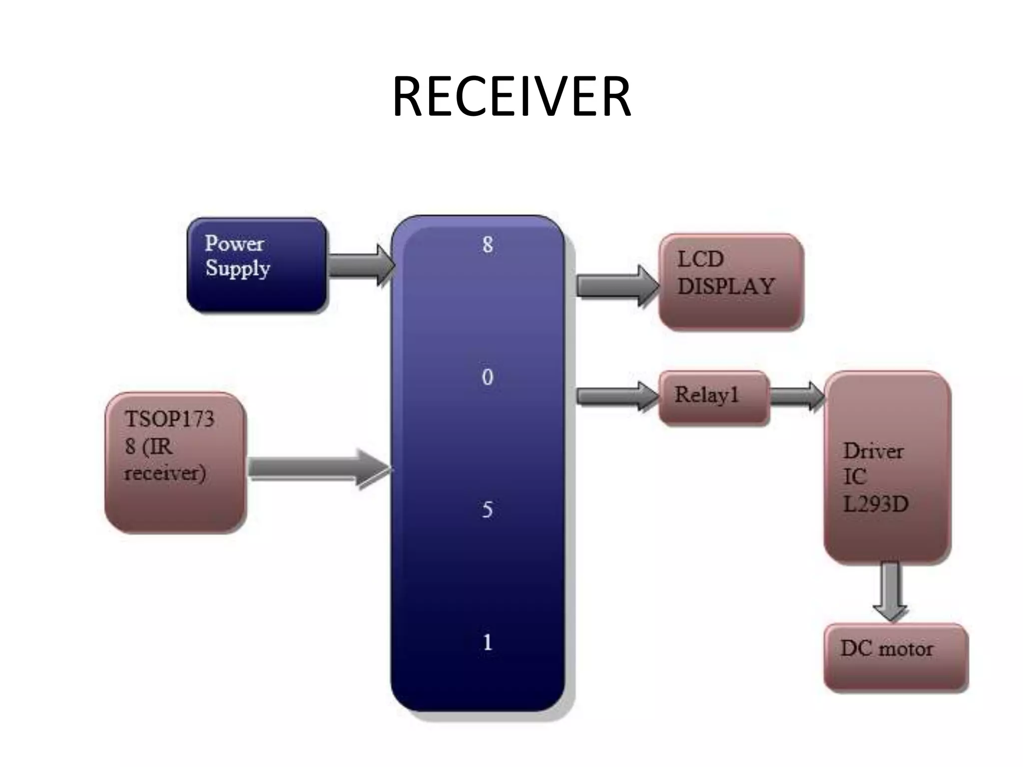
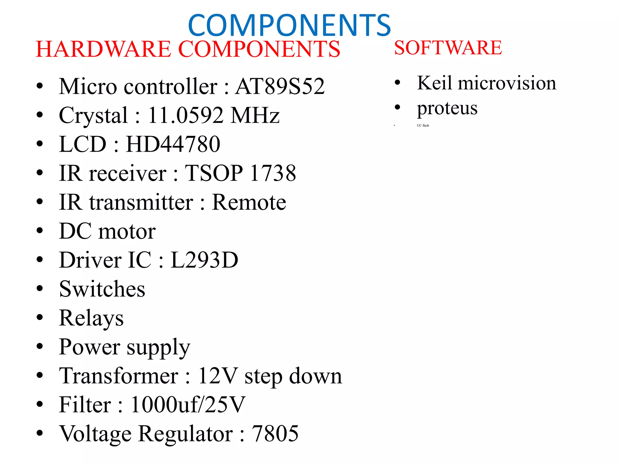
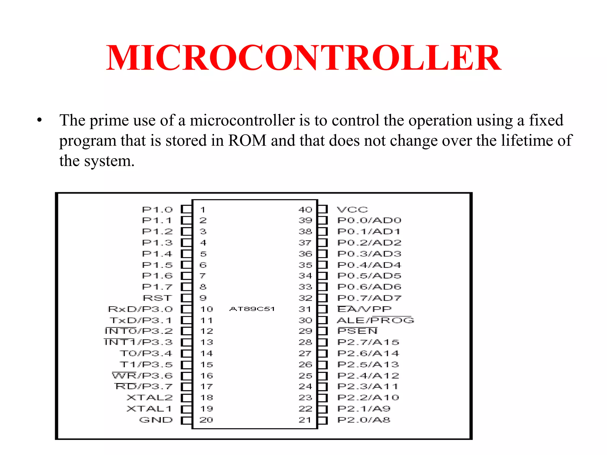
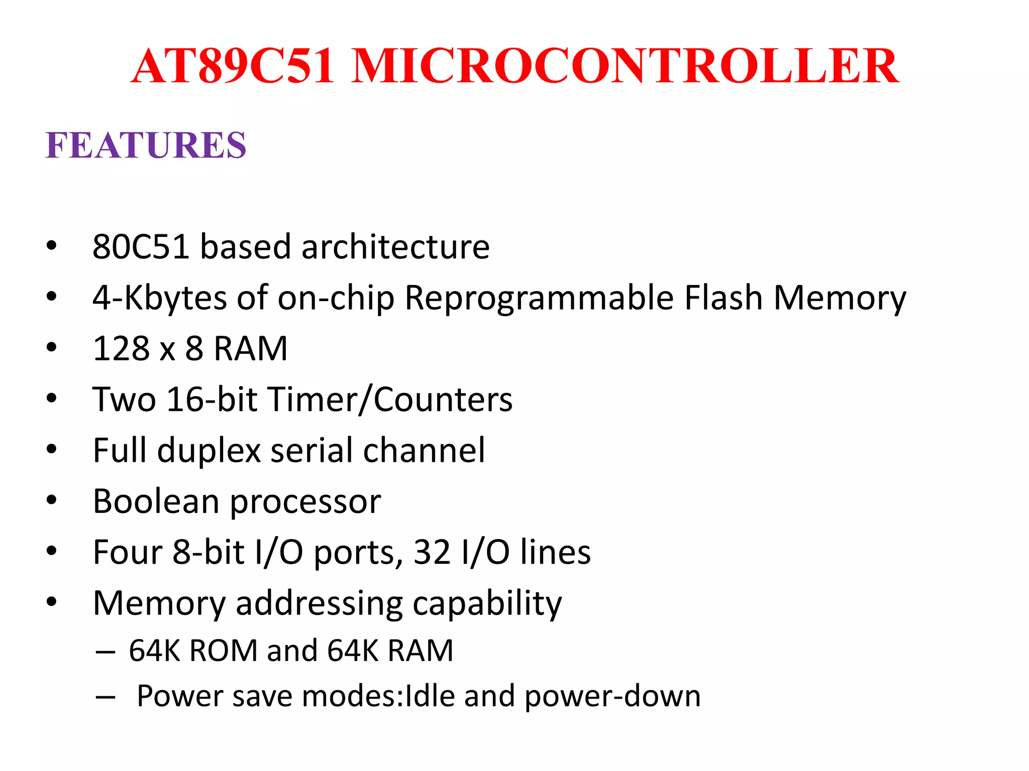
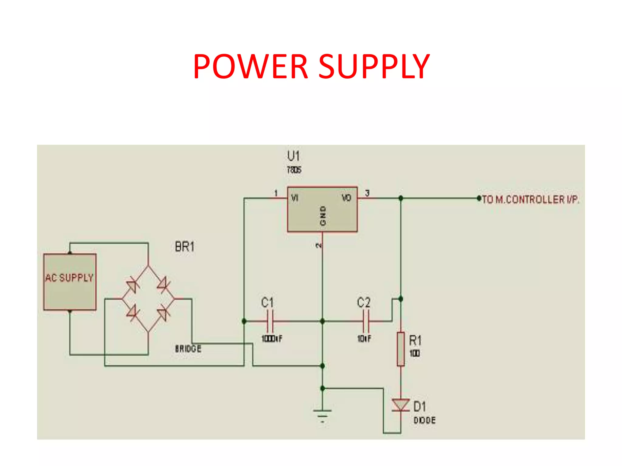
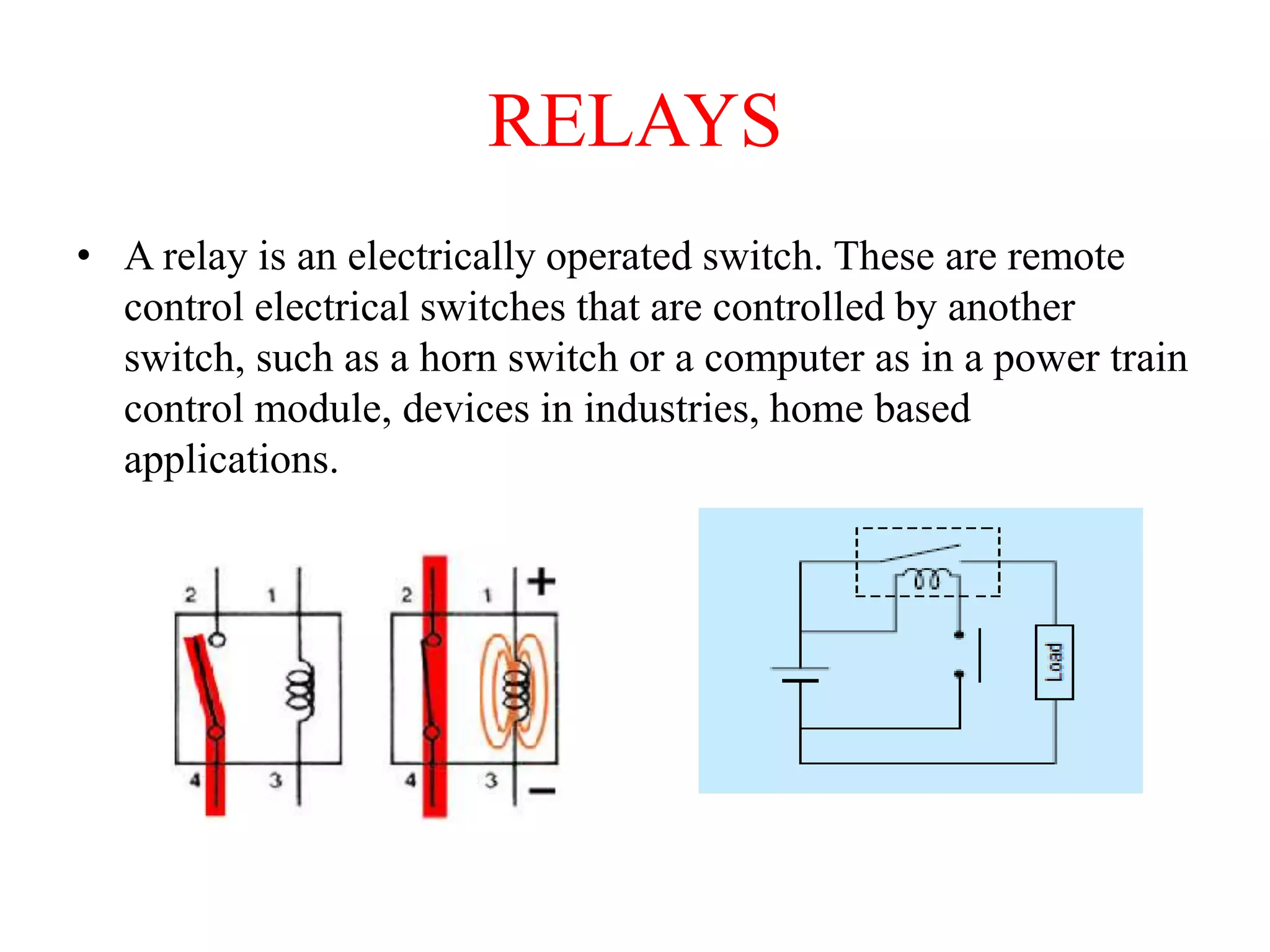
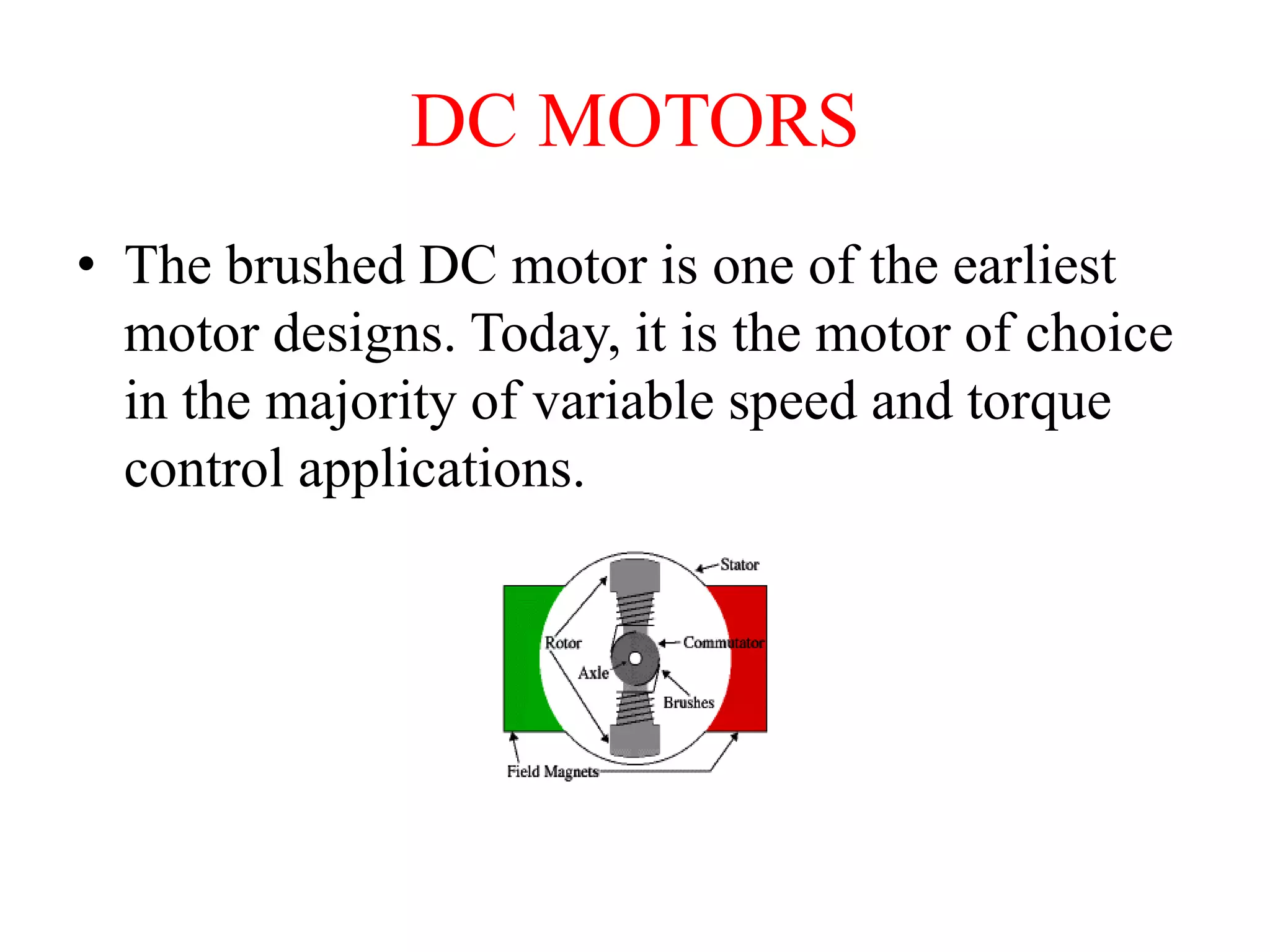
DC MOTOR SPEED DIRECTION
CONTROLLING USING IR
REMOTE
CONTENTS
• Introduction
• Components
• Block diagram
• Receiver section
• Microcontroller Pin configuration
• AT895c1 microcontroller features
• Power supply
• Transformer
• Relays
• Dc Motors
• Applications
• Advantages
• Future Scope
• Conclusion
INTRODUCTION
• The project is built around an 8051 microcontroller, IR remote
and an IR receiver.
• And a DC motor will also be interfaced to the controller through
a driver IC L293D.
• IR remote acts as the transmitter in this project.
• In the remote, 4 buttons are
• being dedicated to control the motor. Now, it is the job of the
controller to read the data
• received from the receiver and to perform the predefined task of
rotating the motor
• clockwise, anticlockwise and increasing, decreasing the speed of
the dc motor.
BLOCK DIAGRAM
Transmitter section:
IR REMOTE
RECEIVER
COMPONENTS
HARDWARE COMPONENTS
• Micro controller : AT89S52
• Crystal : 11.0592 MHz
• LCD : HD44780
• IR receiver : TSOP 1738
• IR transmitter : Remote
• DC motor
• Driver IC : L293D
• Switches
• Relays
• Power supply
• Transformer : 12V step down
• Filter : 1000uf/25V
• Voltage Regulator : 7805
SOFTWARE
• Keil microvision
• proteus
• UC flash
MICROCONTROLLER
• The prime use of a microcontroller is to control the operation using a fixed
program that is stored in ROM and that does not change over the lifetime of
the system.
AT89C51 MICROCONTROLLER
FEATURES
• 80C51 based architecture
• 4-Kbytes of on-chip Reprogrammable Flash Memory
• 128 x 8 RAM
• Two 16-bit Timer/Counters
• Full duplex serial channel
• Boolean processor
• Four 8-bit I/O ports, 32 I/O lines
• Memory addressing capability
– 64K ROM and 64K RAM
– Power save modes:Idle and power-down
POWER SUPPLY
TRANSFORMER
• A transformer is a device that transfers electrical energy from one circuit to
another through inductively coupled conductors—the transformer's coils
Transformer symbol Transformer
RELAYS
• A relay is an electrically operated switch. These are remote
control electrical switches that are controlled by another
switch, such as a horn switch or a computer as in a power train
control module, devices in industries, home based
applications.
DC MOTORS
• The brushed DC motor is one of the earliest
motor designs. Today, it is the motor of choice
in the majority of variable speed and torque
control applications.
APPLICATIONS
• To control a high-voltage circuit with a low-voltage signal, as
in some types of modems,
• To control a high-current circuit with a low-current signal, as
in the starter solenoid of an automobile,
• To detect and isolate faults on transmission and distribution
lines by opening and closing circuit breakers (protection
relays).
• Normally closed contacts. When a current is passed through
the relay coil, the relay operates and opens the contacts that
carry the supply current.
ADVANTAGES
• Easy to understand design
• Easy to control speed
• Easy to control torque
• Simple, cheap drive design
FUTURE SCOPE
• The work done can be further extended in future to design a
closed loop system which could control the speed to a more
précised value and error can be easily reduced by giving
feedback signal form the sensor to the controller using the
DAQ card.
• receive the system status and information via SMS.
CONCLUSION
• The speed control and the direction control of
the dc motor is achieved from the wireless and
radio frequency technology with Pulse Width
Modulation and H-Bridge.
• calibration procedure, but there is still value in
having a controller that can be built with no
exotic equipment.
THANK YOU

Dc motor speed and direction contrlling using IR remote

  • 1.
    DC MOTOR SPEEDDIRECTION CONTROLLING USING IR REMOTE
  • 2.
    CONTENTS • Introduction • Components •Block diagram • Receiver section • Microcontroller Pin configuration • AT895c1 microcontroller features • Power supply • Transformer • Relays • Dc Motors • Applications • Advantages • Future Scope • Conclusion
  • 3.
    INTRODUCTION • The projectis built around an 8051 microcontroller, IR remote and an IR receiver. • And a DC motor will also be interfaced to the controller through a driver IC L293D. • IR remote acts as the transmitter in this project. • In the remote, 4 buttons are • being dedicated to control the motor. Now, it is the job of the controller to read the data • received from the receiver and to perform the predefined task of rotating the motor • clockwise, anticlockwise and increasing, decreasing the speed of the dc motor.
  • 4.
  • 5.
  • 6.
    COMPONENTS HARDWARE COMPONENTS • Microcontroller : AT89S52 • Crystal : 11.0592 MHz • LCD : HD44780 • IR receiver : TSOP 1738 • IR transmitter : Remote • DC motor • Driver IC : L293D • Switches • Relays • Power supply • Transformer : 12V step down • Filter : 1000uf/25V • Voltage Regulator : 7805 SOFTWARE • Keil microvision • proteus • UC flash
  • 7.
    MICROCONTROLLER • The primeuse of a microcontroller is to control the operation using a fixed program that is stored in ROM and that does not change over the lifetime of the system.
  • 8.
    AT89C51 MICROCONTROLLER FEATURES • 80C51based architecture • 4-Kbytes of on-chip Reprogrammable Flash Memory • 128 x 8 RAM • Two 16-bit Timer/Counters • Full duplex serial channel • Boolean processor • Four 8-bit I/O ports, 32 I/O lines • Memory addressing capability – 64K ROM and 64K RAM – Power save modes:Idle and power-down
  • 9.
  • 10.
    TRANSFORMER • A transformeris a device that transfers electrical energy from one circuit to another through inductively coupled conductors—the transformer's coils Transformer symbol Transformer
  • 11.
    RELAYS • A relayis an electrically operated switch. These are remote control electrical switches that are controlled by another switch, such as a horn switch or a computer as in a power train control module, devices in industries, home based applications.
  • 12.
    DC MOTORS • Thebrushed DC motor is one of the earliest motor designs. Today, it is the motor of choice in the majority of variable speed and torque control applications.
  • 13.
    APPLICATIONS • To controla high-voltage circuit with a low-voltage signal, as in some types of modems, • To control a high-current circuit with a low-current signal, as in the starter solenoid of an automobile, • To detect and isolate faults on transmission and distribution lines by opening and closing circuit breakers (protection relays). • Normally closed contacts. When a current is passed through the relay coil, the relay operates and opens the contacts that carry the supply current.
  • 14.
    ADVANTAGES • Easy tounderstand design • Easy to control speed • Easy to control torque • Simple, cheap drive design
  • 15.
    FUTURE SCOPE • Thework done can be further extended in future to design a closed loop system which could control the speed to a more précised value and error can be easily reduced by giving feedback signal form the sensor to the controller using the DAQ card. • receive the system status and information via SMS.
  • 16.
    CONCLUSION • The speedcontrol and the direction control of the dc motor is achieved from the wireless and radio frequency technology with Pulse Width Modulation and H-Bridge. • calibration procedure, but there is still value in having a controller that can be built with no exotic equipment.
  • 17.

Editor's Notes

  • #11 Transformer symbol Transformer