Downloaded 326 times

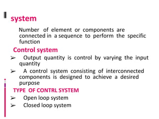
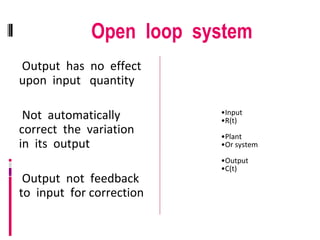
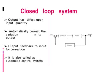
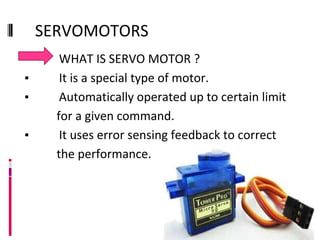
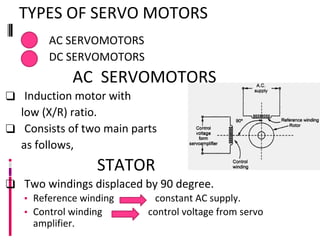
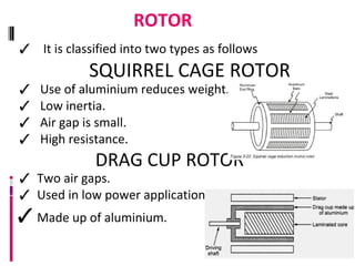
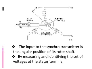
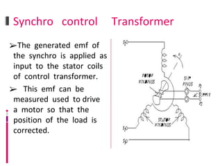
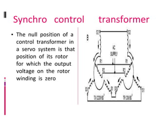
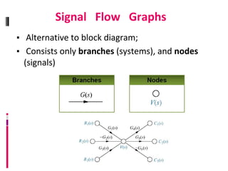
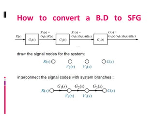
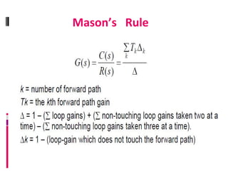


This document discusses different types of control systems, including open loop and closed loop systems. It describes open loop systems as having output that does not affect input quantity and lacks feedback, while closed loop systems have output that affects input and uses feedback to automatically correct variations in output. The document also covers servomotors, including AC and DC servomotors, and synchros which can be used to control angular position remotely or correct changes in position. Signal flow graphs are introduced as an alternative to block diagrams to represent systems.