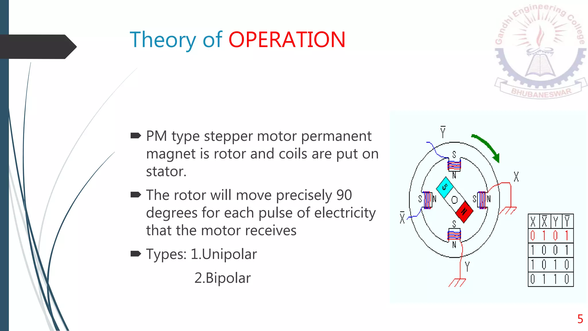
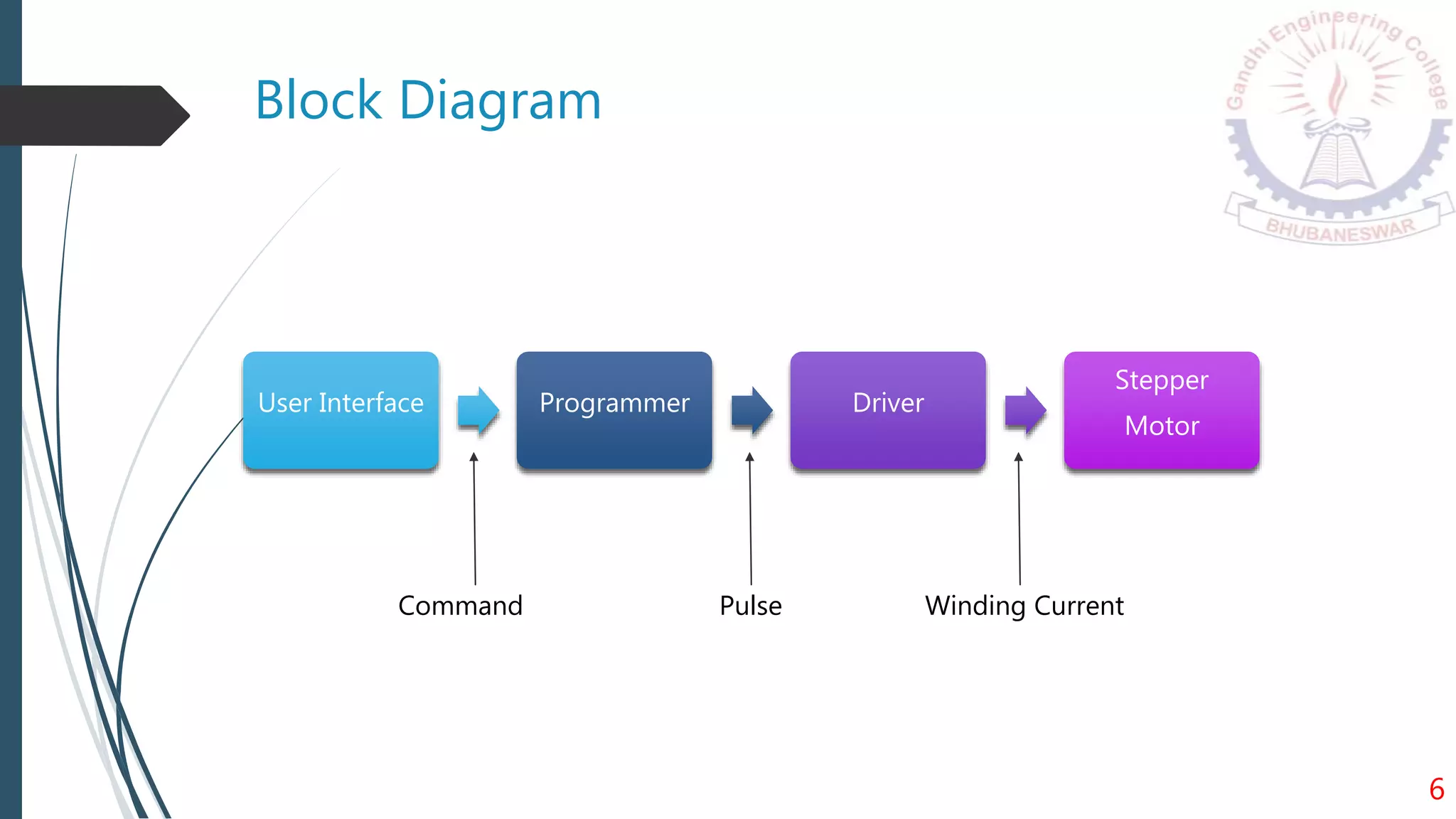
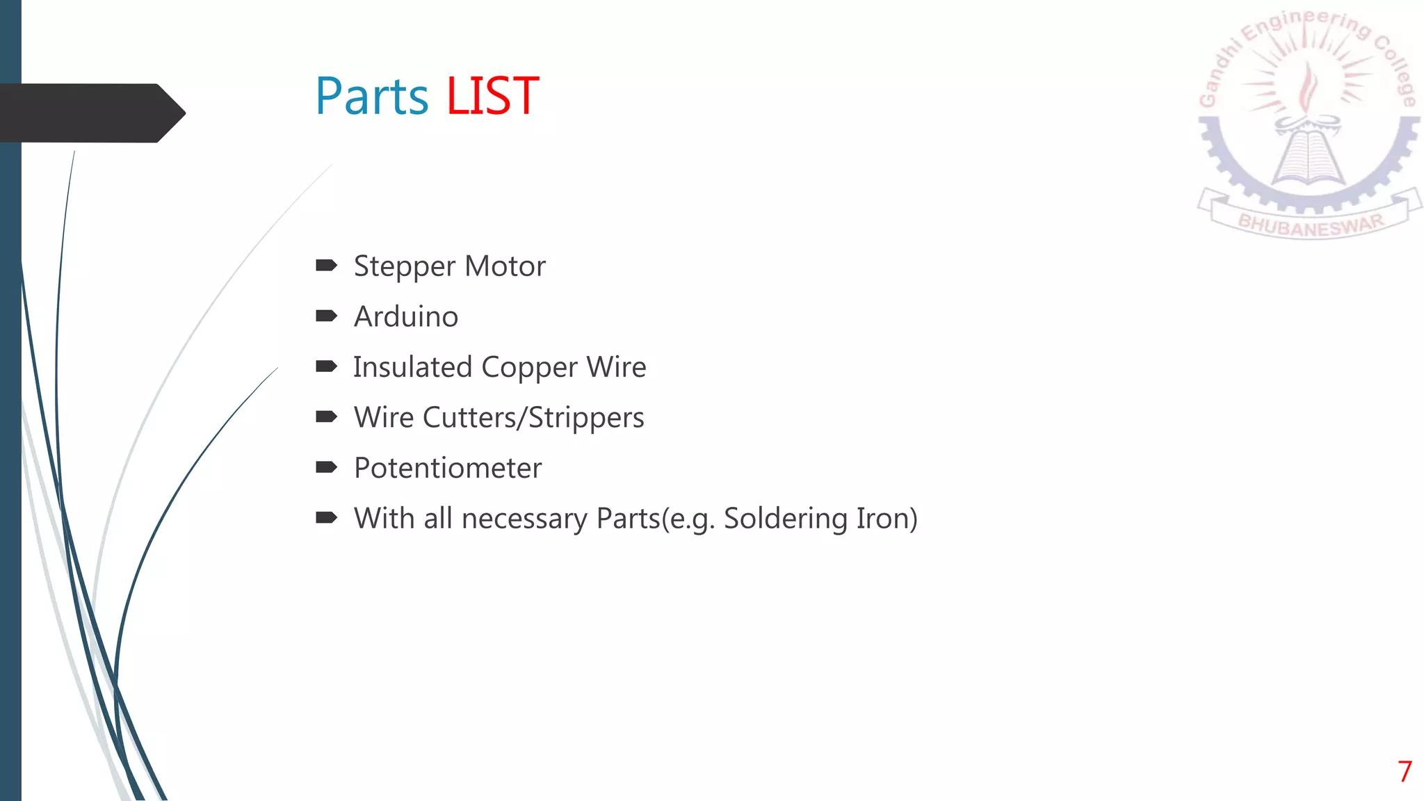
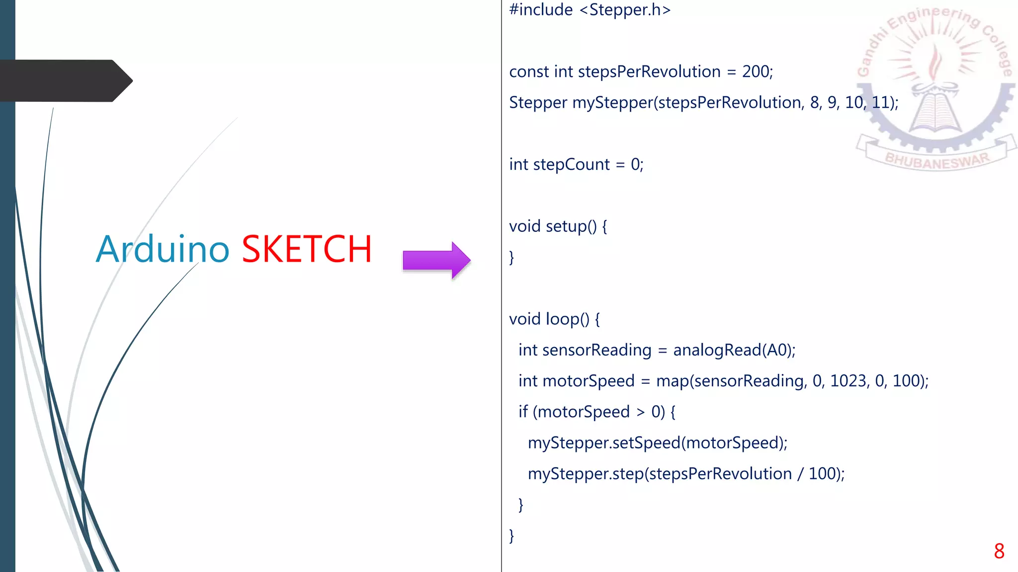
STEPPER MOTOR SPEED
CONTROL
USING ARDUINO UNO R3
By: SAUMYA RANJAN BEHURA
In this project my aim is to control stepper
motor positional accuracy in precise manner.
With the help of latest and popular
development board like Arduino Uno.
1
INTRODUCTION
CONTENTS:
 Brief idea about ARDUINO
 Intro to Stepper Motor
 Theory of operation
 Parts List
 Arduino Sketch
 Driver IC
 Schematic Diagram
 Estimation
 Advantages
 Conclusion
23
Brief Idea about ARDUINO UNO
Microcontroller ATmega328P
Operating Voltage 5V
Input Voltage (recommended) 7-12V
Input Voltage (limit) 6-20V
Digital I/O Pins 14 (of which 6 provide PWM output)
PWM Digital I/O Pins 6
Analog Input Pins 6
DC Current per I/O Pin 20 mA
DC Current for 3.3V Pin 50 mA
Flash Memory 32 KB (ATmega328P) of which 0.5 KB used by bootloader
SRAM 2 KB (ATmega328P)
EEPROM 1 KB (ATmega328P)
Clock Speed 16 MHz
LED_BUILTIN 13
Length 68.6 mm
Width 53.4 mm
Weight 25 g 3
Intro to STEPPER MOTOR
 Electromechanical device which converts
electrical pulses into discrete mechanical
movements.
 Shaft of a stepper motor rotates in discrete step
increments when electrical pulses are applied .
 Sequence of the applied pulses is directly related
to the direction of motor shaft’s rotation.
 Speed of rotation is directly related to the
frequency of input pulses applied.
4
Theory of OPERATION
 PM type stepper motor permanent
magnet is rotor and coils are put on
stator.
 The rotor will move precisely 90
degrees for each pulse of electricity
that the motor receives
 Types: 1.Unipolar
2.Bipolar
5
Block Diagram
6
User Interface Programmer Driver
Stepper
Motor
Command Pulse Winding Current
Parts LIST
 Stepper Motor
 Arduino
 Insulated Copper Wire
 Wire Cutters/Strippers
 Potentiometer
 With all necessary Parts(e.g. Soldering Iron)
7
Arduino SKETCH
#include <Stepper.h>
const int stepsPerRevolution = 200;
Stepper myStepper(stepsPerRevolution, 8, 9, 10, 11);
int stepCount = 0;
void setup() {
}
void loop() {
int sensorReading = analogRead(A0);
int motorSpeed = map(sensorReading, 0, 1023, 0, 100);
if (motorSpeed > 0) {
myStepper.setSpeed(motorSpeed);
myStepper.step(stepsPerRevolution / 100);
}
}
8
10
Driver IC
 ULN2803 IC(Darlington Pair)
9
Schematic Diagram
10
ESTIMATION (approx. = Rs.1135)
Serial
No.
Name Specification Quntity Price
1
Stepper
Motor
Unipolar,5V 1 400
2 Driver IC ULN2803 1 85
3 Arduino Uno UNO,12V 1 500
4
Potentiomet
er
10k 1 46
5
Voltage
Regulator
7809 1 33
6 Diodes 1N4007 4 21
7 Capacitors 1000uf 2 8
8 Resistors According to req. 10 22
9 Wires -do- 1 20
11
Advantages
 The rotation angle of the motor is proportional to the input pulse
 Excellent response to starting, stopping/reversing
 The motors response to digital input pulses provides open-loop control
 It is possible to achieve very low speed synchronous rotation
 A wide range of rotational speeds can be realized
 Very reliable since there are no contact brushes in the motor
 Accuracy of 3 – 5% of a step and this error is non cumulative from one step to the
next
12
Conclusion
 Controlling speed of stepper motor with arduino can be
studied throughout this project.
 These are very popular in our day to day life due to a lot of
advantages and also in digital control circuits, such as
robotics because they are ideally suited for receiving digital
pulses for step control
13
THANK YOU
14

Stepper speed control

  • 1.
    STEPPER MOTOR SPEED CONTROL USINGARDUINO UNO R3 By: SAUMYA RANJAN BEHURA
  • 2.
    In this projectmy aim is to control stepper motor positional accuracy in precise manner. With the help of latest and popular development board like Arduino Uno. 1 INTRODUCTION
  • 3.
    CONTENTS:  Brief ideaabout ARDUINO  Intro to Stepper Motor  Theory of operation  Parts List  Arduino Sketch  Driver IC  Schematic Diagram  Estimation  Advantages  Conclusion 23
  • 4.
    Brief Idea aboutARDUINO UNO Microcontroller ATmega328P Operating Voltage 5V Input Voltage (recommended) 7-12V Input Voltage (limit) 6-20V Digital I/O Pins 14 (of which 6 provide PWM output) PWM Digital I/O Pins 6 Analog Input Pins 6 DC Current per I/O Pin 20 mA DC Current for 3.3V Pin 50 mA Flash Memory 32 KB (ATmega328P) of which 0.5 KB used by bootloader SRAM 2 KB (ATmega328P) EEPROM 1 KB (ATmega328P) Clock Speed 16 MHz LED_BUILTIN 13 Length 68.6 mm Width 53.4 mm Weight 25 g 3
  • 5.
    Intro to STEPPERMOTOR  Electromechanical device which converts electrical pulses into discrete mechanical movements.  Shaft of a stepper motor rotates in discrete step increments when electrical pulses are applied .  Sequence of the applied pulses is directly related to the direction of motor shaft’s rotation.  Speed of rotation is directly related to the frequency of input pulses applied. 4
  • 6.
    Theory of OPERATION PM type stepper motor permanent magnet is rotor and coils are put on stator.  The rotor will move precisely 90 degrees for each pulse of electricity that the motor receives  Types: 1.Unipolar 2.Bipolar 5
  • 7.
    Block Diagram 6 User InterfaceProgrammer Driver Stepper Motor Command Pulse Winding Current
  • 8.
    Parts LIST  StepperMotor  Arduino  Insulated Copper Wire  Wire Cutters/Strippers  Potentiometer  With all necessary Parts(e.g. Soldering Iron) 7
  • 9.
    Arduino SKETCH #include <Stepper.h> constint stepsPerRevolution = 200; Stepper myStepper(stepsPerRevolution, 8, 9, 10, 11); int stepCount = 0; void setup() { } void loop() { int sensorReading = analogRead(A0); int motorSpeed = map(sensorReading, 0, 1023, 0, 100); if (motorSpeed > 0) { myStepper.setSpeed(motorSpeed); myStepper.step(stepsPerRevolution / 100); } } 8
  • 10.
  • 11.
    Driver IC  ULN2803IC(Darlington Pair) 9
  • 12.
  • 13.
    ESTIMATION (approx. =Rs.1135) Serial No. Name Specification Quntity Price 1 Stepper Motor Unipolar,5V 1 400 2 Driver IC ULN2803 1 85 3 Arduino Uno UNO,12V 1 500 4 Potentiomet er 10k 1 46 5 Voltage Regulator 7809 1 33 6 Diodes 1N4007 4 21 7 Capacitors 1000uf 2 8 8 Resistors According to req. 10 22 9 Wires -do- 1 20 11
  • 14.
    Advantages  The rotationangle of the motor is proportional to the input pulse  Excellent response to starting, stopping/reversing  The motors response to digital input pulses provides open-loop control  It is possible to achieve very low speed synchronous rotation  A wide range of rotational speeds can be realized  Very reliable since there are no contact brushes in the motor  Accuracy of 3 – 5% of a step and this error is non cumulative from one step to the next 12
  • 15.
    Conclusion  Controlling speedof stepper motor with arduino can be studied throughout this project.  These are very popular in our day to day life due to a lot of advantages and also in digital control circuits, such as robotics because they are ideally suited for receiving digital pulses for step control 13
  • 16.