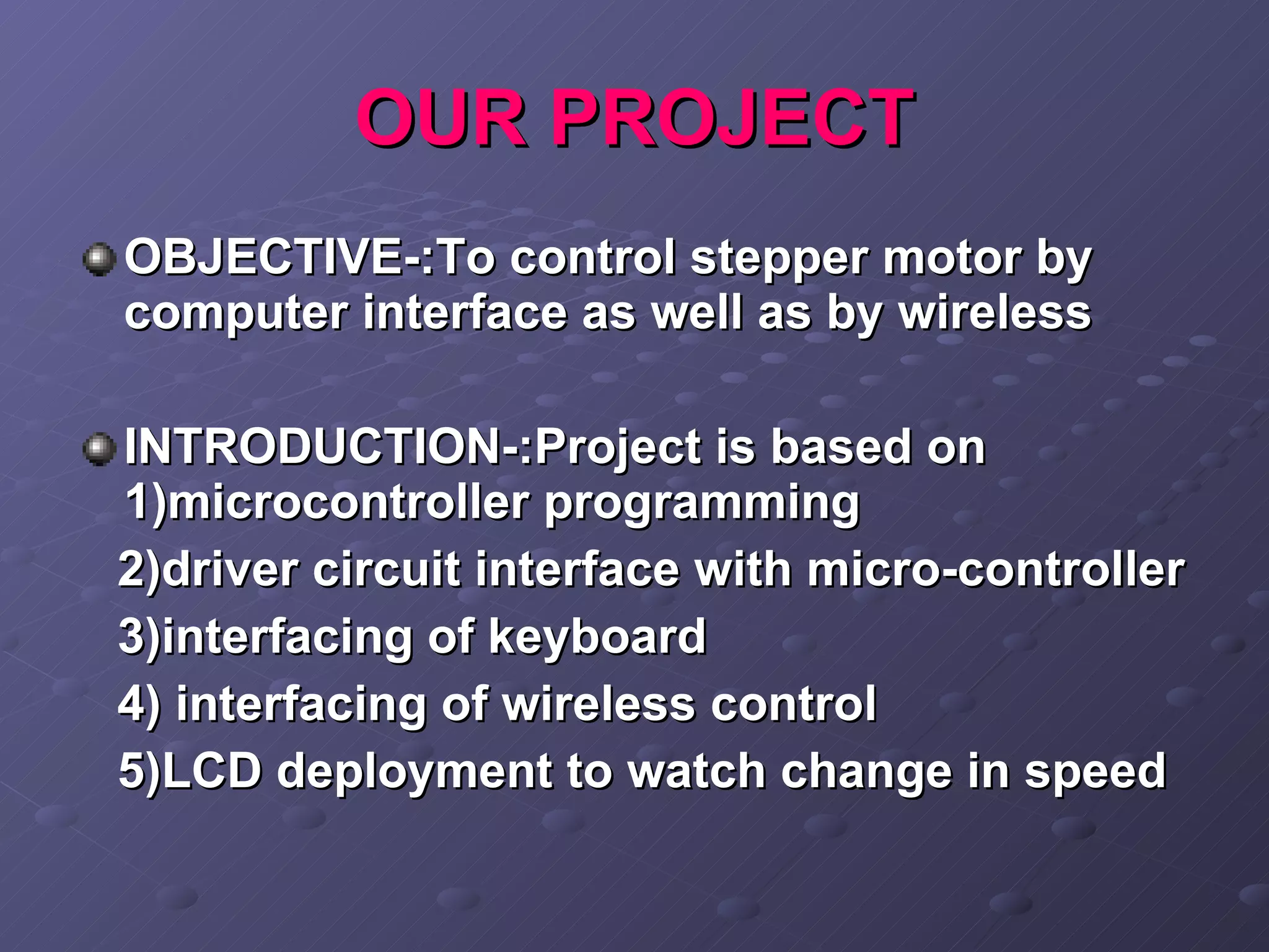
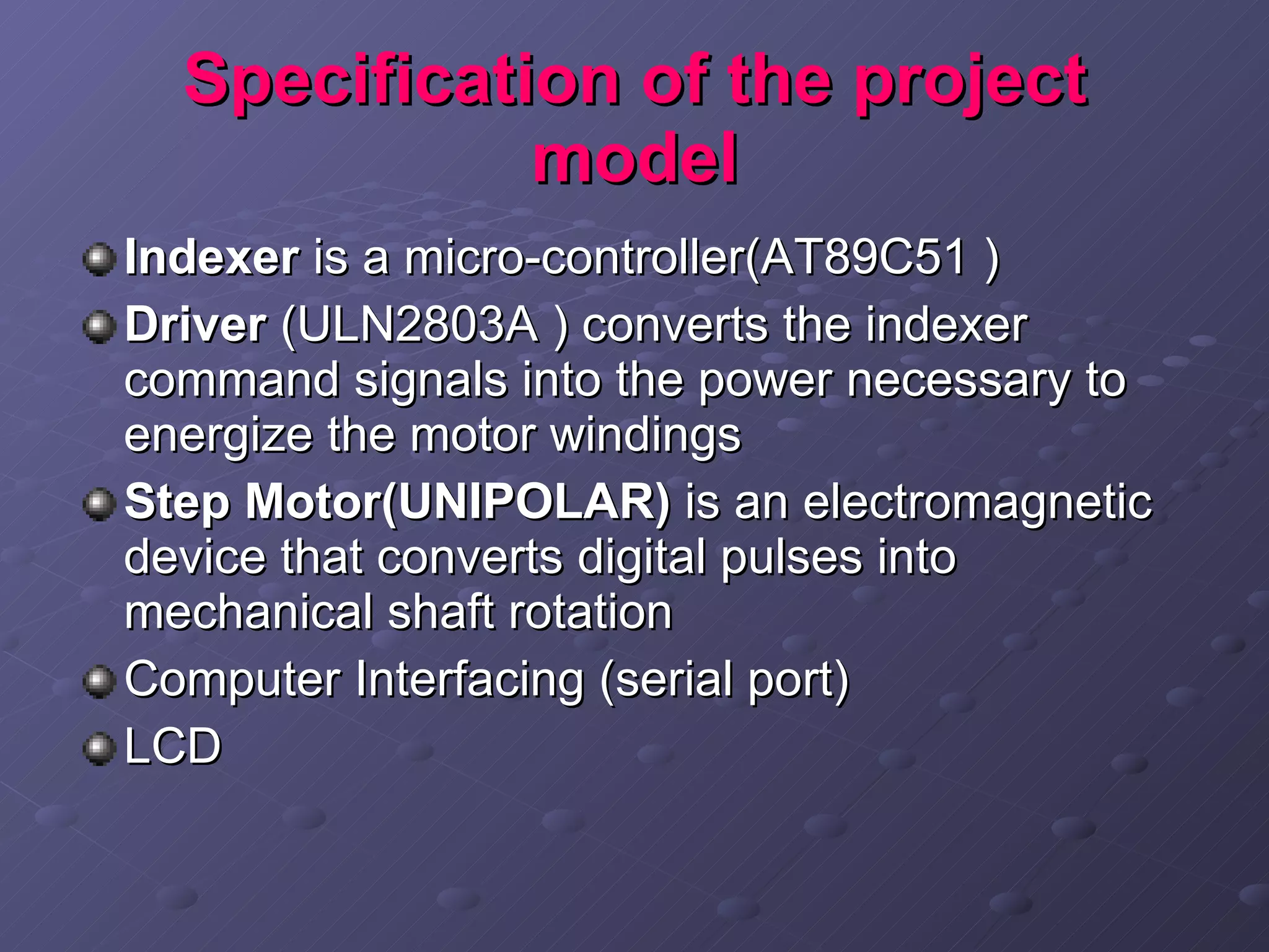
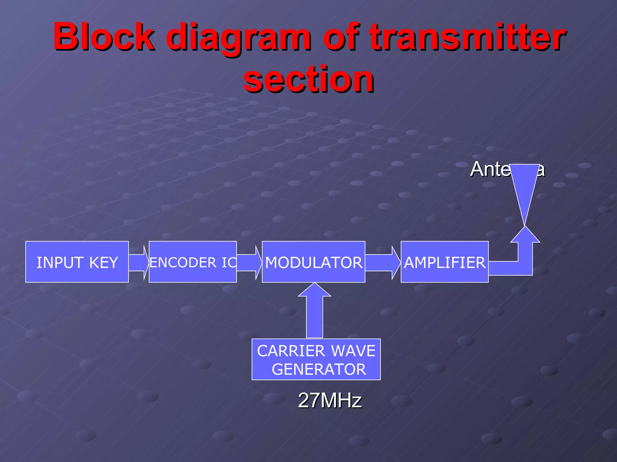
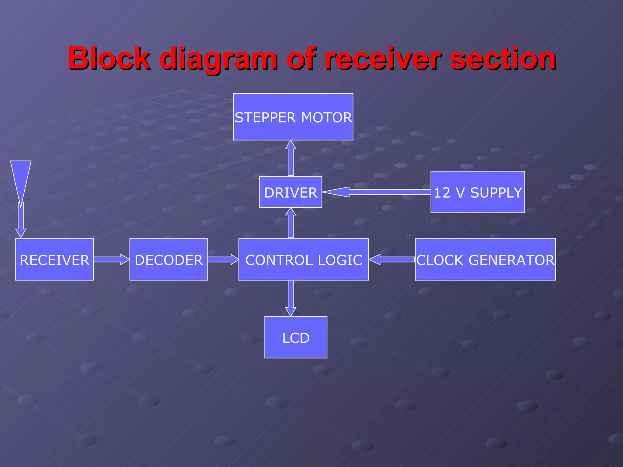
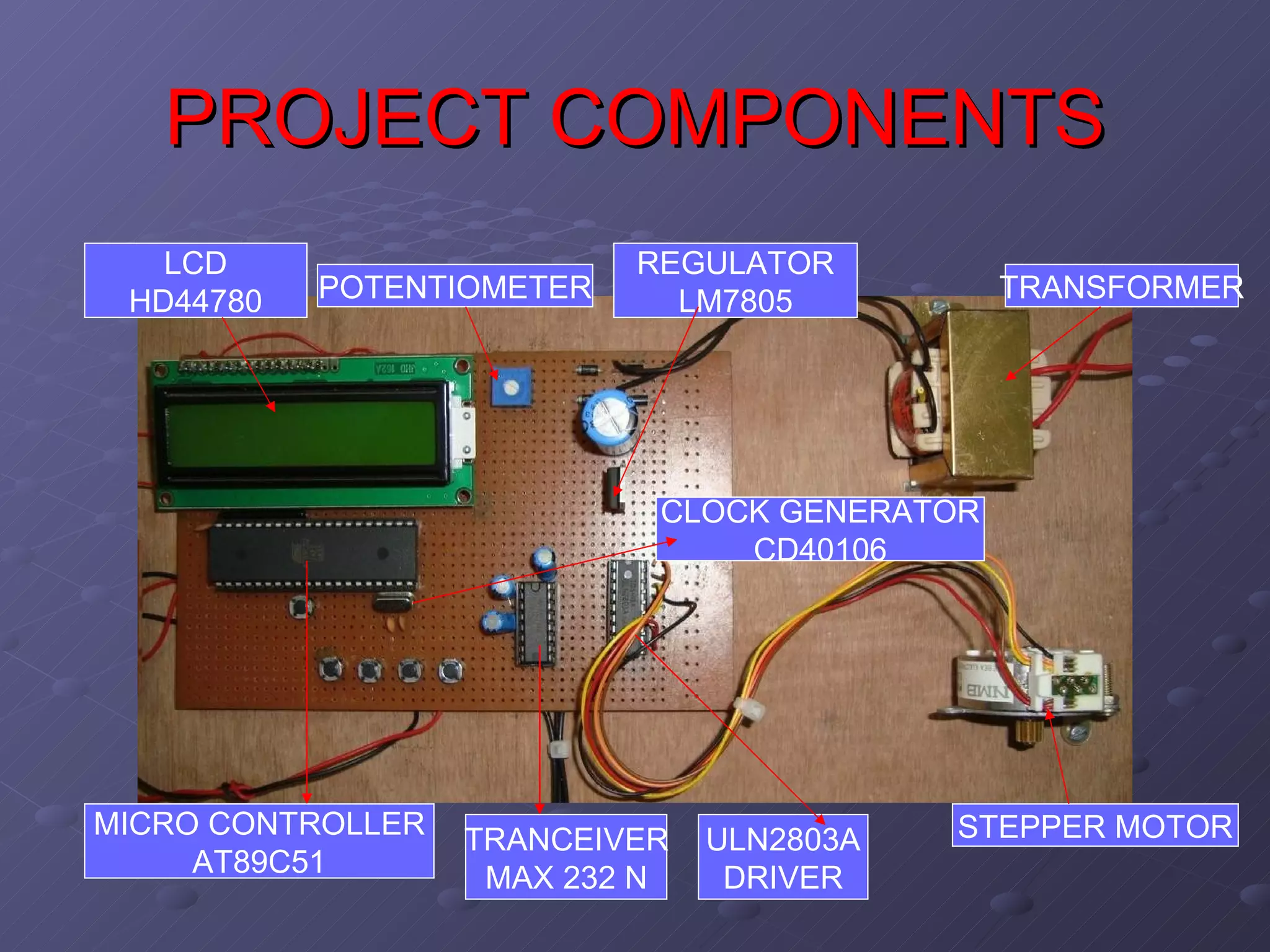
STEPPER MOTOR CONTROL THROUGH WIRELESS Submitted by (RAVI KUMAR,ASHWANI GARG,VINOD KUMAR,MANOJ GOSWAMI.VIBHOOTI KUMAR SINHA) FOURTH YEAR ELECTRONICS & TELECOMMUNICATION Guided by Mr. Aman dua  ,  Mrs. Shiva Jaiswal LECTURER (ELECTRONICS & TELECOMMUNICATION ) COLLEGE OF ENGINEERING ROORKEE ROORKEE – 247 667
ACKNOWLEDGEMENTS We express our deepest thanks to Mr. AMAN DUA  Project Guide   Lecturer   Ms.DIVYA ARORA   Project Coordinator  ,  Lecturer Mr. B D PATEL   Head of Electronics & Telecom Dept   College of Engineering Roorkee ,Roorkee
OUR PROJECT OBJECTIVE-:To control stepper motor by computer interface as well as by wireless INTRODUCTION-:Project is based on 1)microcontroller programming  2)driver circuit interface with micro-controller  3)interfacing of keyboard 4) interfacing of wireless control 5)LCD deployment to watch change in speed
stepper motor performance characteristic Rotation in both directions Precision angular incremental changes Repetition of accurate motion  A holding torque at zero speed  Capability for digital control.
BLOCK DIAGRAM OF PROJECT USER INTERFACE INDEXER DRIVER MOTOR HIGH LEVEL COMMANDS STEP PULSES MOTOR CURRENT
Specification of the project model Indexer  is a micro-controller(AT89C51 )  Driver  (ULN2803A ) converts the indexer command signals into the power necessary to energize the motor windings Step Motor(UNIPOLAR)  is an electromagnetic device that converts digital pulses into mechanical shaft rotation  Computer Interfacing (serial port) LCD
STEPPER MOTOR   Brushless Synchronous electric motor divide a full rotation into a large number of steps   stepper motor uses an open loop with no feedback, position being determined by a software counter in the controlling computer.  Rotation in both directions
INTERNAL STRUCTURE   OF STEPPER MOTOR F=i (dl x B) ROTOR (permanent magnet) TEETH (to define  precise rotation STATOR (carry coil  for current  Flow)
How stepper motor works? Stepper motor converts electrical pulses into specific rotational movements Hence ,Torque is generated by alternately magnetizing the stator teeth electrically, and permanent magnet rotor teeth try to align up with stator teeth
One Phase Steps
 
One Phase On Mode (Full Step mode)
One Phase On Steps Sequence
MICROCONTROLLER   Special purpose computers  Dedicated to one task (i.e. no multi tasking) Low-power device. It has a dedicated input device. In our project we are using AT89C51 MICROCONTROLLER
AT89C51 MICROCONTROLLER CMOS 8-bit. 4K bytes of Flash programmable and erasable read only memory (PEROM).  “ AT” represents Atmel’s high-density nonvolatile memory technology. Power consumption of 50 mW Compatible with MCS-51 instruction set Fully Static Operation: 0 Hz to 24 MHz Continued..
Continued.. 128 x 8-Bit Internal RAM Two 16-Bit Timer/Counters Six Interrupt Sources 32 Programmable I/O Lines
ULN 2803 DRIVER   suited  for  interfacing  between  low-level  logic  circuitry  and multiple peripheral power  loads USER INTERFACE INDEXER DRIVER MOTOR HIGH LEVEL COMMANDS STEP PULSES MOTOR CURRENT
Internal architecture of ULN2803 Seven open collector darlington pairs with common emitters . 500mA to each of the seven drivers , Output voltage to 95 V . power loads totaling over 230 W we can connect to it. Each channel rated at 500mAand can withstand peak currents of 600mA(i.e. it is highly reliable)  TTL, DTL, PMOS or CMOS-Compatible Inputs
REGULATOR   LM78XX  available in the TO-220/D-PAK package  fixed output voltages  thermal shut down and safe operating area protection  Output Current up to 1A  Output Voltages of 5, 6, 8, 9, 10, 12, 15, 18, 24V  Short Circuit Protection
LIQUID CRYSTAL DISPLAY   Hitachi's HD44780  It has 1 controller with14 Pins  configurations of 8x1 characters, 16x2, and 20x4 . The largest such configuration is 40x4 characters.we are using 8x1 LCD
IC CD40106 HEX Schmitt Trigger (NOT Gate) Features Wide supply voltage range:3V to 15V High noise immunity: 0.7VDD Low power TTL compatibility Hysteresis 0.4VDD & 0.2VDD guaranteed Hysteresis 0.4VDD & 0.2VDD guaranteed 9 7 - 8 + 14
COMPUTER INTERFACING   We can connect our project to serial port of computer and can control the speed of it using keyboard. Serial ports   are   typically identified on IBM compatible computers as COM ports  It folllows synchronous data link standard(RS 232) serial communication  is the process of sending data  one bit at one time
SERIAL Vs PARALLEL COMM.
TRANSCEIVER transceiver  is a device that has both a  transmitter  and a  receiver   An electronic switch allows the transmitter and receiver to be connected to the same antenna.  it is impossible to receive signals while transmitting (called half duplex comm. ) Some transceivers are designed to allow reception of signals during transmission periods (called full duplex comm.)  contd..
contd.. A logic 0 is represented  voltage +3V to +15VDC and a logic 1 is represented by  -3VDC to -15VDC. 250kbps Operation Low Power: 60mW  RS232 Compatible High Impedance  State When Off or  Powered Down
This PROJECT can be used perfectly in many areas. This device is easy to implement in hardware and software means. This circuit is cost effective, consume less power and take minimum space. CONCLUSION
Block diagram of transmitter section Antenna 27MHz AMPLIFIER MODULATOR ENCODER IC INPUT KEY CARRIER WAVE GENERATOR
Block diagram of receiver section CLOCK GENERATOR CONTROL LOGIC DECODER RECEIVER STEPPER MOTOR DRIVER LCD 12 V SUPPLY
PROJECT COMPONENTS MICRO CONTROLLER AT89C51 TRANCEIVER MAX 232 N ULN2803A DRIVER REGULATOR LM7805 STEPPER MOTOR POTENTIOMETER TRANSFORMER CLOCK GENERATOR CD40106 LCD HD44780
FUTURE OF OUR PROJECT Places where we need precise position to be displaced E.g.: 1)Machine tools 2)Disk drives (Hard disk, Floppy Drive) 3)Printers 4)Robotics
THE END THANKS YOU ALL

Steper Motor Control Through Wireless

  • 1.
    STEPPER MOTOR CONTROLTHROUGH WIRELESS Submitted by (RAVI KUMAR,ASHWANI GARG,VINOD KUMAR,MANOJ GOSWAMI.VIBHOOTI KUMAR SINHA) FOURTH YEAR ELECTRONICS & TELECOMMUNICATION Guided by Mr. Aman dua , Mrs. Shiva Jaiswal LECTURER (ELECTRONICS & TELECOMMUNICATION ) COLLEGE OF ENGINEERING ROORKEE ROORKEE – 247 667
  • 2.
    ACKNOWLEDGEMENTS We expressour deepest thanks to Mr. AMAN DUA Project Guide Lecturer Ms.DIVYA ARORA Project Coordinator , Lecturer Mr. B D PATEL Head of Electronics & Telecom Dept College of Engineering Roorkee ,Roorkee
  • 3.
    OUR PROJECT OBJECTIVE-:Tocontrol stepper motor by computer interface as well as by wireless INTRODUCTION-:Project is based on 1)microcontroller programming 2)driver circuit interface with micro-controller 3)interfacing of keyboard 4) interfacing of wireless control 5)LCD deployment to watch change in speed
  • 4.
    stepper motor performancecharacteristic Rotation in both directions Precision angular incremental changes Repetition of accurate motion A holding torque at zero speed Capability for digital control.
  • 5.
    BLOCK DIAGRAM OFPROJECT USER INTERFACE INDEXER DRIVER MOTOR HIGH LEVEL COMMANDS STEP PULSES MOTOR CURRENT
  • 6.
    Specification of theproject model Indexer is a micro-controller(AT89C51 ) Driver (ULN2803A ) converts the indexer command signals into the power necessary to energize the motor windings Step Motor(UNIPOLAR) is an electromagnetic device that converts digital pulses into mechanical shaft rotation Computer Interfacing (serial port) LCD
  • 7.
    STEPPER MOTOR Brushless Synchronous electric motor divide a full rotation into a large number of steps stepper motor uses an open loop with no feedback, position being determined by a software counter in the controlling computer. Rotation in both directions
  • 8.
    INTERNAL STRUCTURE OF STEPPER MOTOR F=i (dl x B) ROTOR (permanent magnet) TEETH (to define precise rotation STATOR (carry coil for current Flow)
  • 9.
    How stepper motorworks? Stepper motor converts electrical pulses into specific rotational movements Hence ,Torque is generated by alternately magnetizing the stator teeth electrically, and permanent magnet rotor teeth try to align up with stator teeth
  • 10.
  • 11.
  • 12.
    One Phase OnMode (Full Step mode)
  • 13.
    One Phase OnSteps Sequence
  • 14.
    MICROCONTROLLER Special purpose computers Dedicated to one task (i.e. no multi tasking) Low-power device. It has a dedicated input device. In our project we are using AT89C51 MICROCONTROLLER
  • 15.
    AT89C51 MICROCONTROLLER CMOS8-bit. 4K bytes of Flash programmable and erasable read only memory (PEROM). “ AT” represents Atmel’s high-density nonvolatile memory technology. Power consumption of 50 mW Compatible with MCS-51 instruction set Fully Static Operation: 0 Hz to 24 MHz Continued..
  • 16.
    Continued.. 128 x8-Bit Internal RAM Two 16-Bit Timer/Counters Six Interrupt Sources 32 Programmable I/O Lines
  • 17.
    ULN 2803 DRIVER suited for interfacing between low-level logic circuitry and multiple peripheral power loads USER INTERFACE INDEXER DRIVER MOTOR HIGH LEVEL COMMANDS STEP PULSES MOTOR CURRENT
  • 18.
    Internal architecture ofULN2803 Seven open collector darlington pairs with common emitters . 500mA to each of the seven drivers , Output voltage to 95 V . power loads totaling over 230 W we can connect to it. Each channel rated at 500mAand can withstand peak currents of 600mA(i.e. it is highly reliable) TTL, DTL, PMOS or CMOS-Compatible Inputs
  • 19.
    REGULATOR LM78XX available in the TO-220/D-PAK package fixed output voltages thermal shut down and safe operating area protection Output Current up to 1A Output Voltages of 5, 6, 8, 9, 10, 12, 15, 18, 24V Short Circuit Protection
  • 20.
    LIQUID CRYSTAL DISPLAY Hitachi's HD44780 It has 1 controller with14 Pins configurations of 8x1 characters, 16x2, and 20x4 . The largest such configuration is 40x4 characters.we are using 8x1 LCD
  • 21.
    IC CD40106 HEXSchmitt Trigger (NOT Gate) Features Wide supply voltage range:3V to 15V High noise immunity: 0.7VDD Low power TTL compatibility Hysteresis 0.4VDD & 0.2VDD guaranteed Hysteresis 0.4VDD & 0.2VDD guaranteed 9 7 - 8 + 14
  • 22.
    COMPUTER INTERFACING We can connect our project to serial port of computer and can control the speed of it using keyboard. Serial ports are typically identified on IBM compatible computers as COM ports It folllows synchronous data link standard(RS 232) serial communication is the process of sending data one bit at one time
  • 23.
  • 24.
    TRANSCEIVER transceiver is a device that has both a transmitter and a receiver An electronic switch allows the transmitter and receiver to be connected to the same antenna. it is impossible to receive signals while transmitting (called half duplex comm. ) Some transceivers are designed to allow reception of signals during transmission periods (called full duplex comm.) contd..
  • 25.
    contd.. A logic0 is represented voltage +3V to +15VDC and a logic 1 is represented by -3VDC to -15VDC. 250kbps Operation Low Power: 60mW RS232 Compatible High Impedance State When Off or Powered Down
  • 26.
    This PROJECT canbe used perfectly in many areas. This device is easy to implement in hardware and software means. This circuit is cost effective, consume less power and take minimum space. CONCLUSION
  • 27.
    Block diagram oftransmitter section Antenna 27MHz AMPLIFIER MODULATOR ENCODER IC INPUT KEY CARRIER WAVE GENERATOR
  • 28.
    Block diagram ofreceiver section CLOCK GENERATOR CONTROL LOGIC DECODER RECEIVER STEPPER MOTOR DRIVER LCD 12 V SUPPLY
  • 29.
    PROJECT COMPONENTS MICROCONTROLLER AT89C51 TRANCEIVER MAX 232 N ULN2803A DRIVER REGULATOR LM7805 STEPPER MOTOR POTENTIOMETER TRANSFORMER CLOCK GENERATOR CD40106 LCD HD44780
  • 30.
    FUTURE OF OURPROJECT Places where we need precise position to be displaced E.g.: 1)Machine tools 2)Disk drives (Hard disk, Floppy Drive) 3)Printers 4)Robotics
  • 31.