Downloaded 23 times
![JOYSTICK BASED DC MOTOR
CONTROL
PROJECT GUIDE - Mr. Rajkumar Rajoria
TEAM MEMBERS - Vaishnavi Agrawal [0905EC131178]
Shivani Bhargava [0905EC131152]
Electronics & Comm. Engineering Dept.](https://image.slidesharecdn.com/slideshare-161201041402/75/JOYSTICK-BASED-DC-MOTOR-SPEED-CONTROL-SYSTEM-by-VAISHNAVI-AGRAWAL-1-2048.jpg)
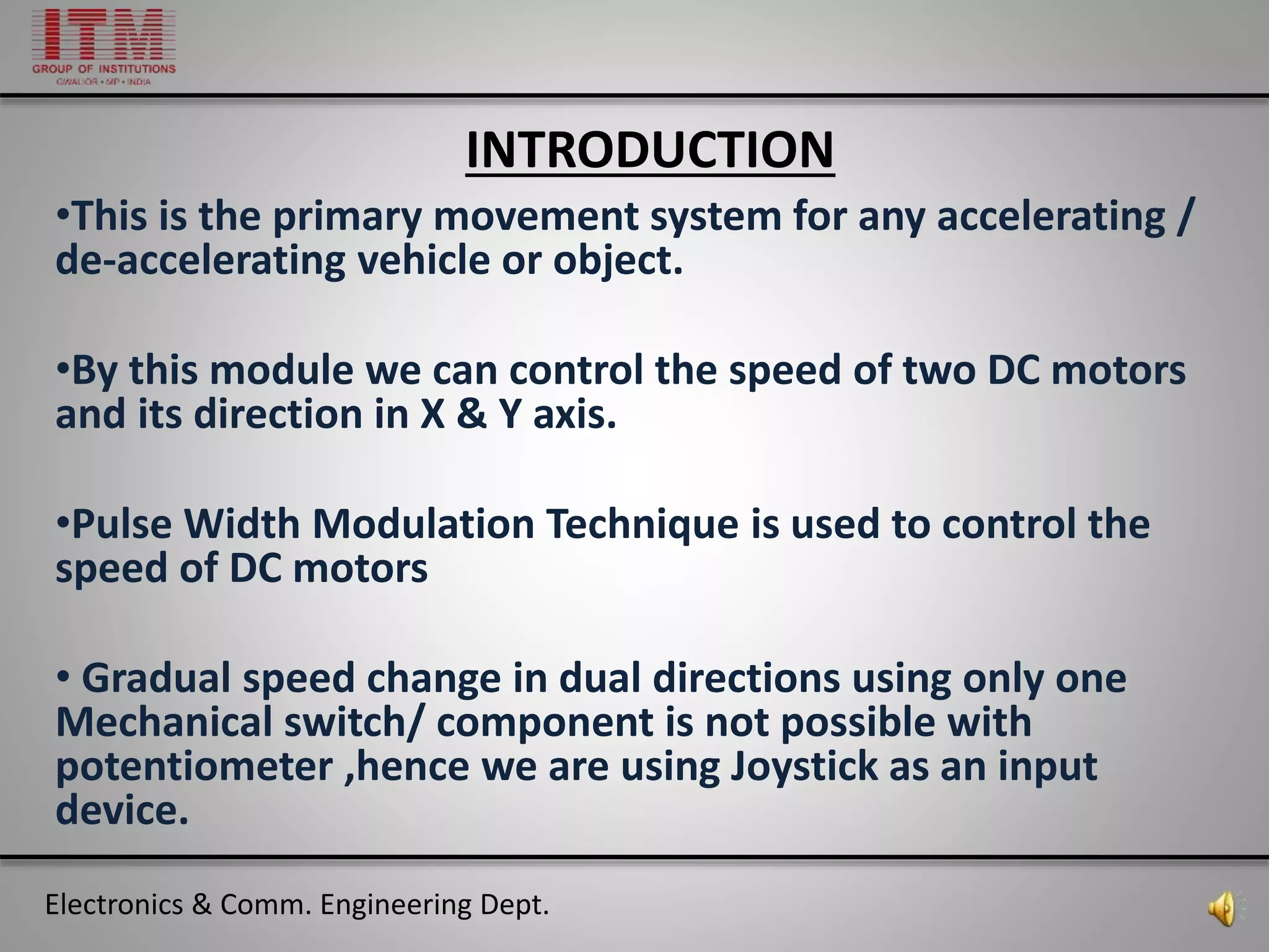
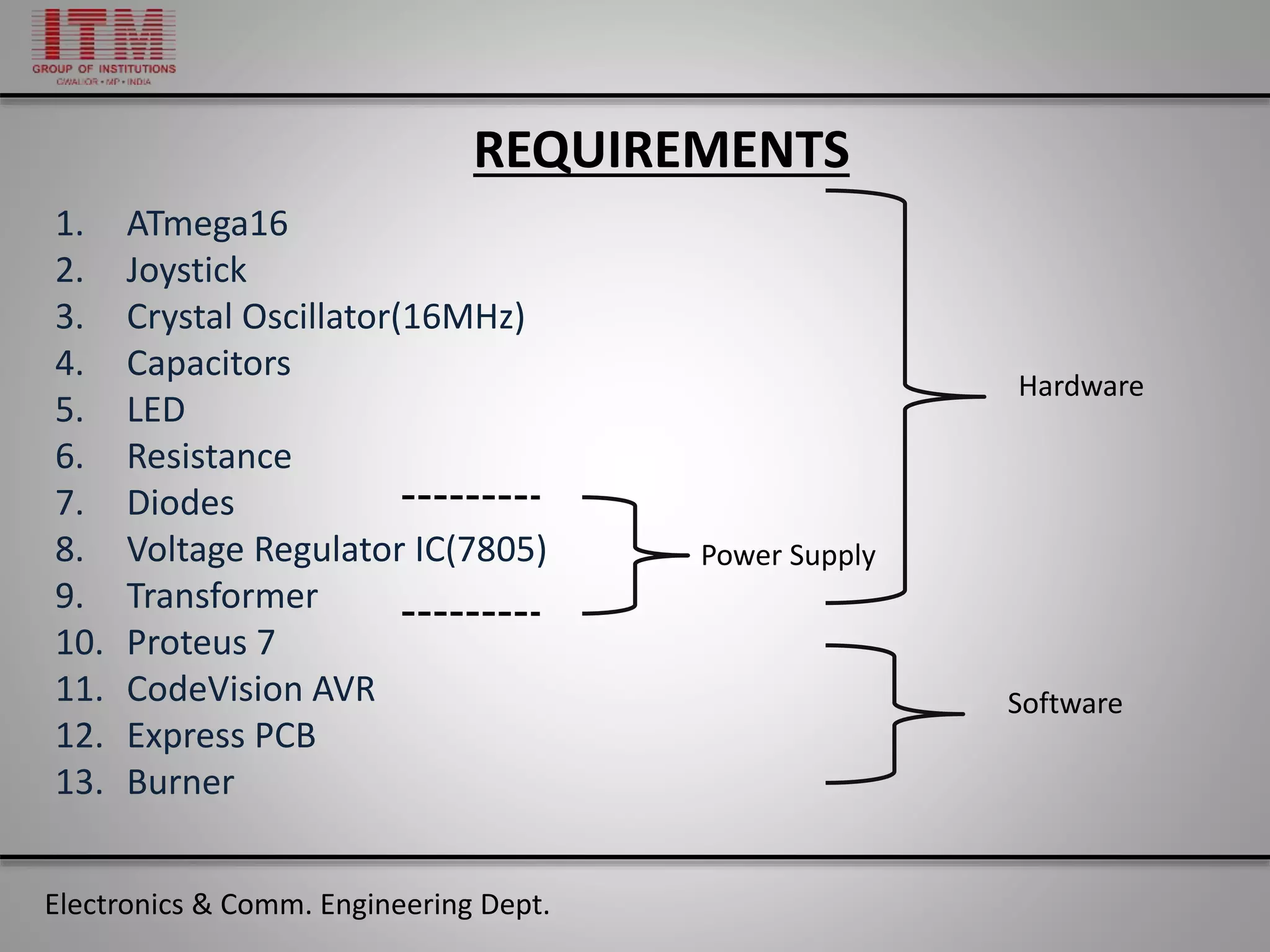
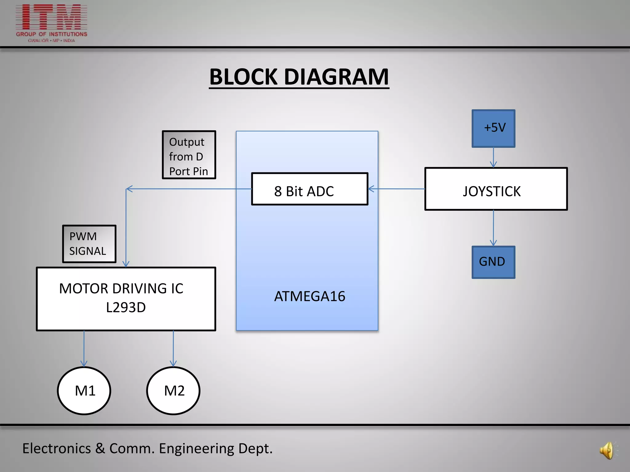
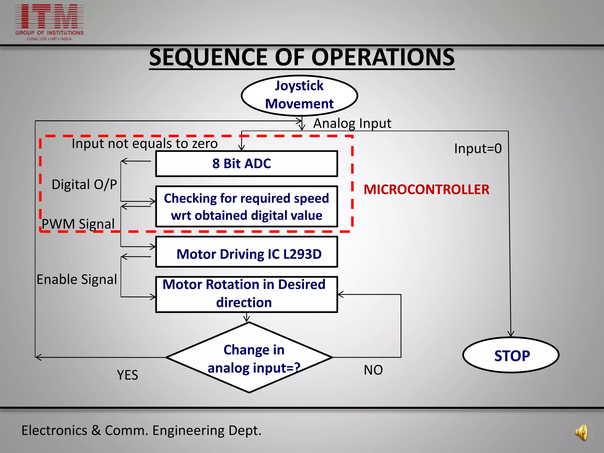
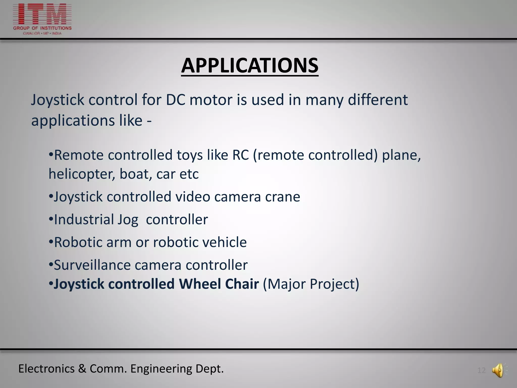
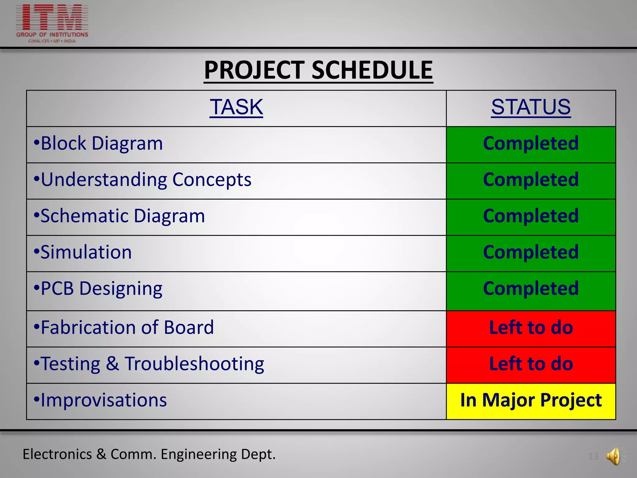

This document outlines a project guide for controlling DC motors using a joystick, highlighting the necessary components such as an ATmega16 microcontroller and PWM technique. The project includes detailed sections on requirements, block diagrams, operation concepts, and applications in fields like robotics and remote-controlled vehicles. Additionally, it provides the project schedule, budget, and references for further reading.


![Share 'speed control_of_dc_motor_using_microcontroller.pptx'[1][1]](https://cdn.slidesharecdn.com/ss_thumbnails/sharespeedcontrolofdcmotorusingmicrocontroller-181012151950-thumbnail.jpg?width=640&height=640&fit=bounds)


