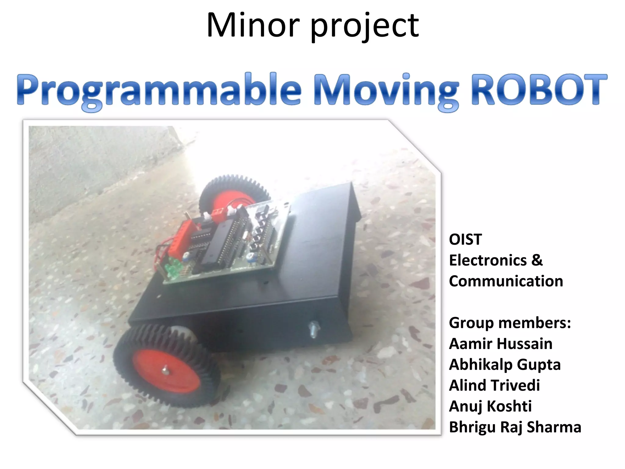
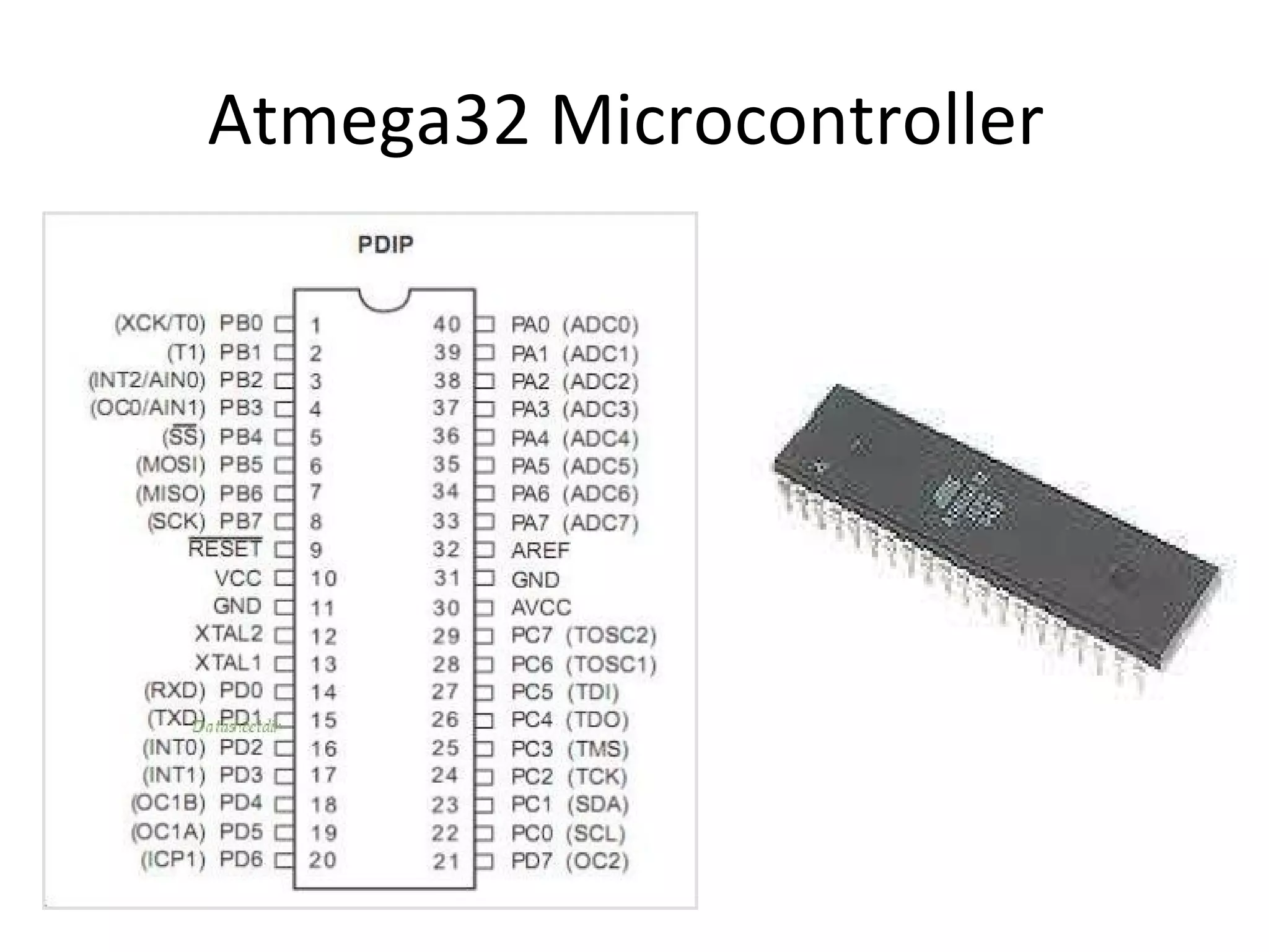
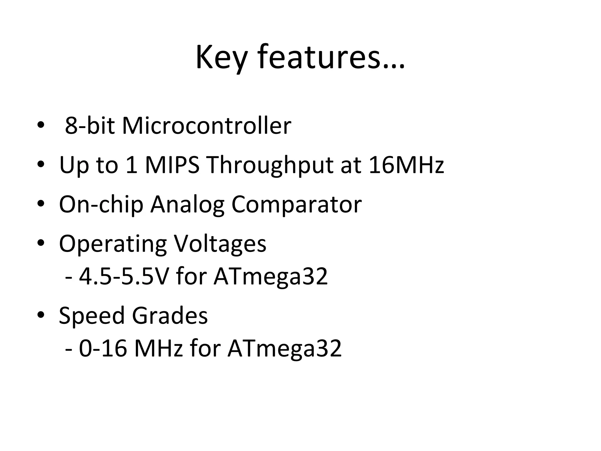
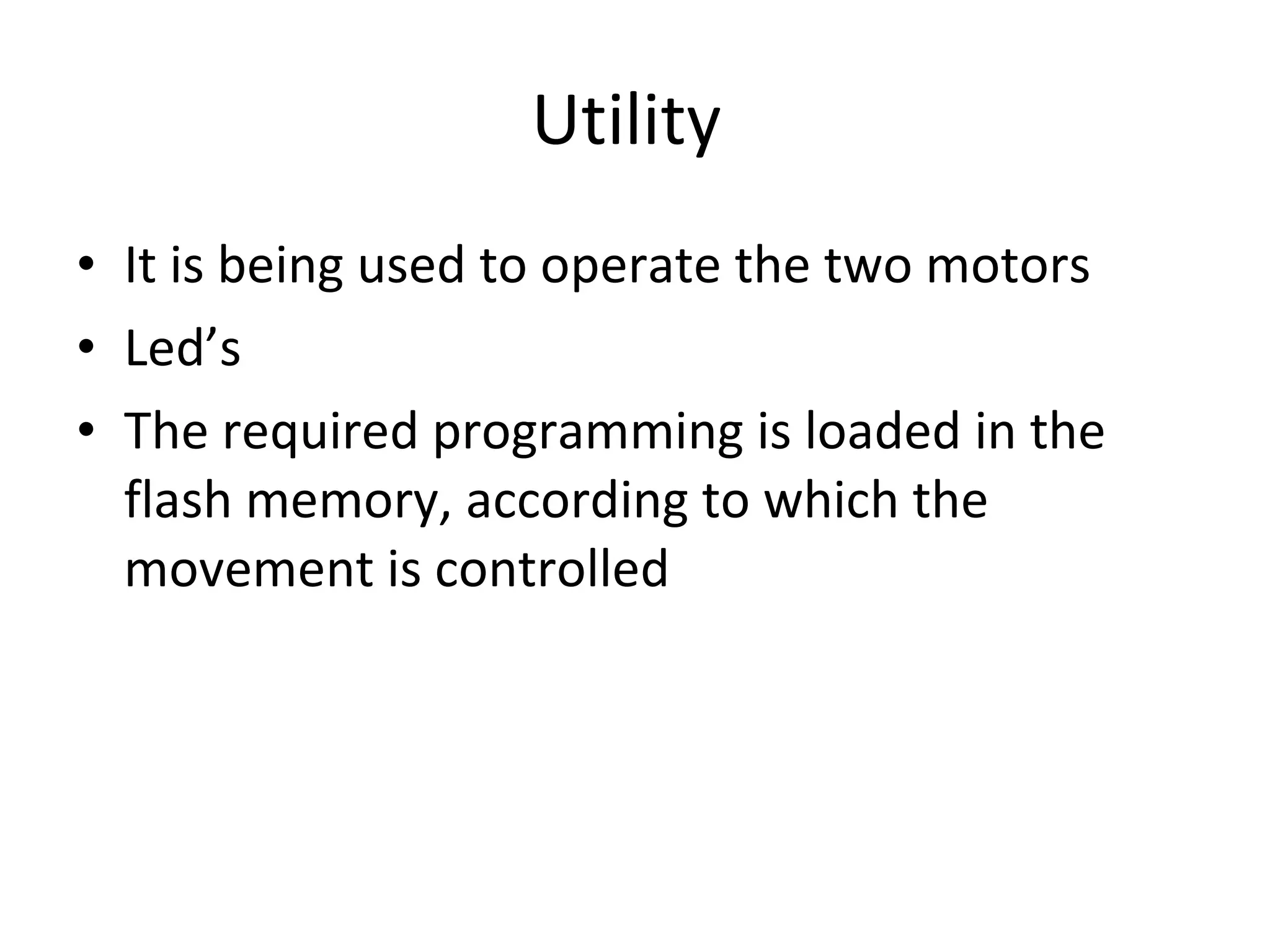
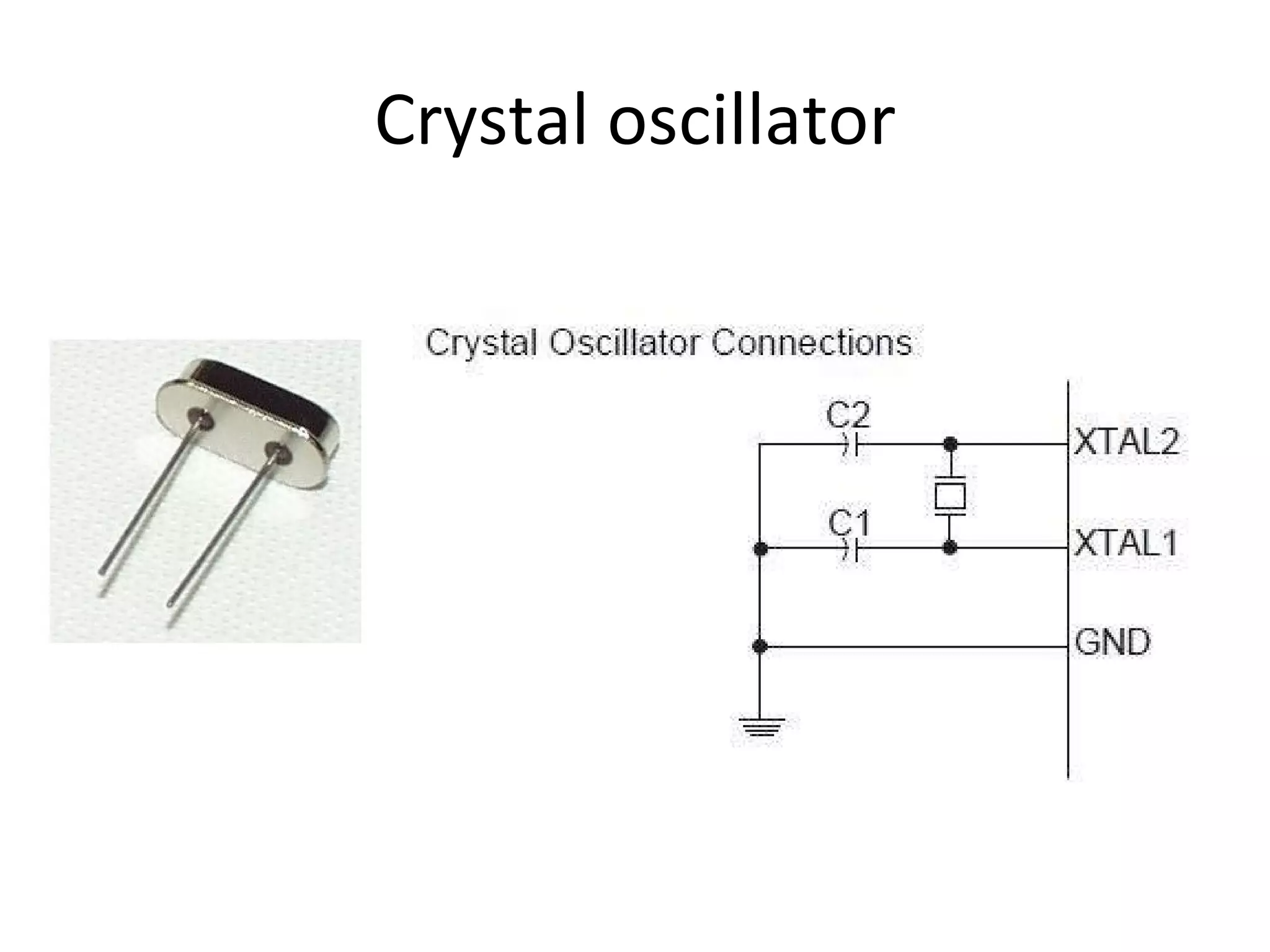
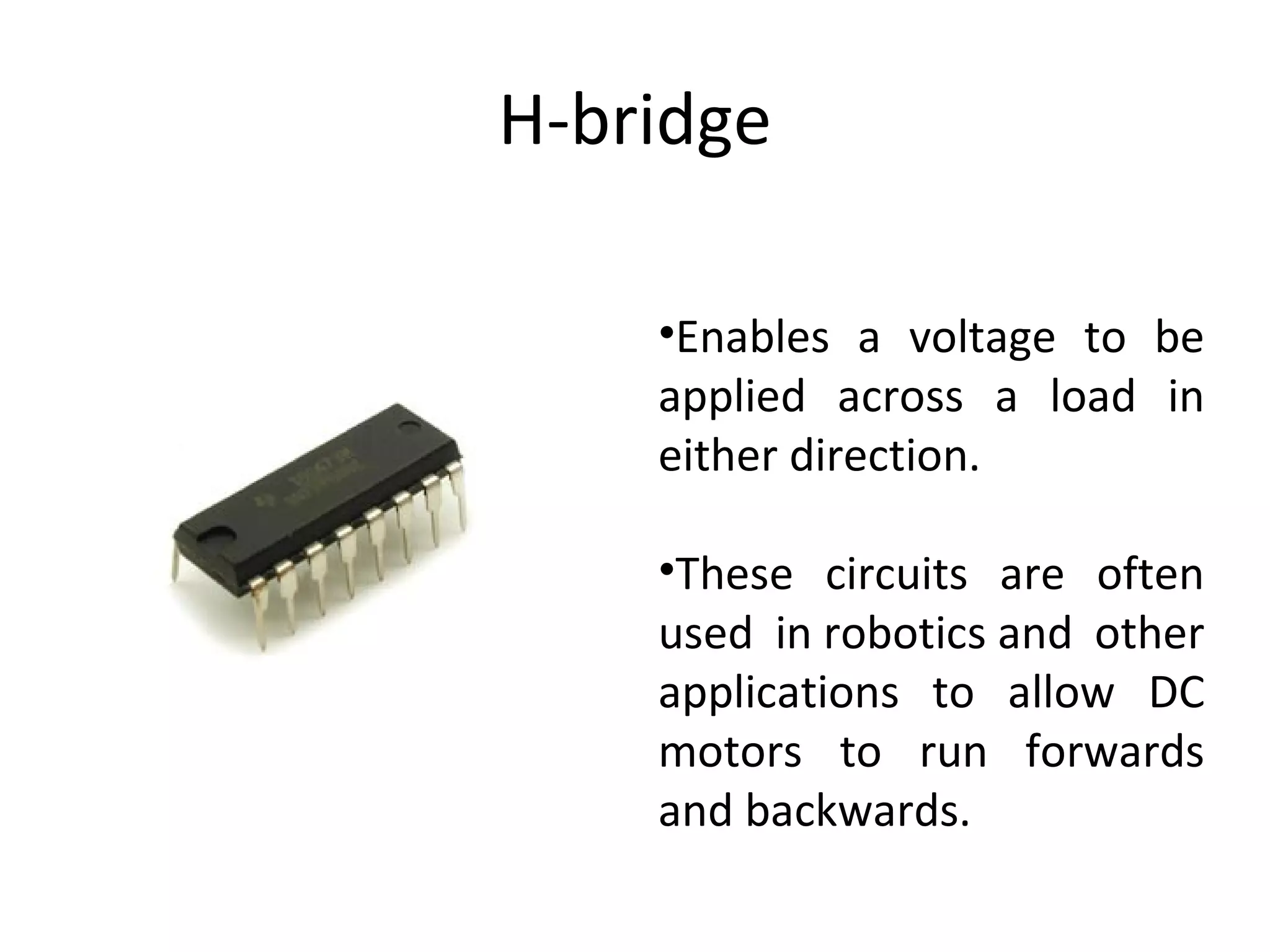
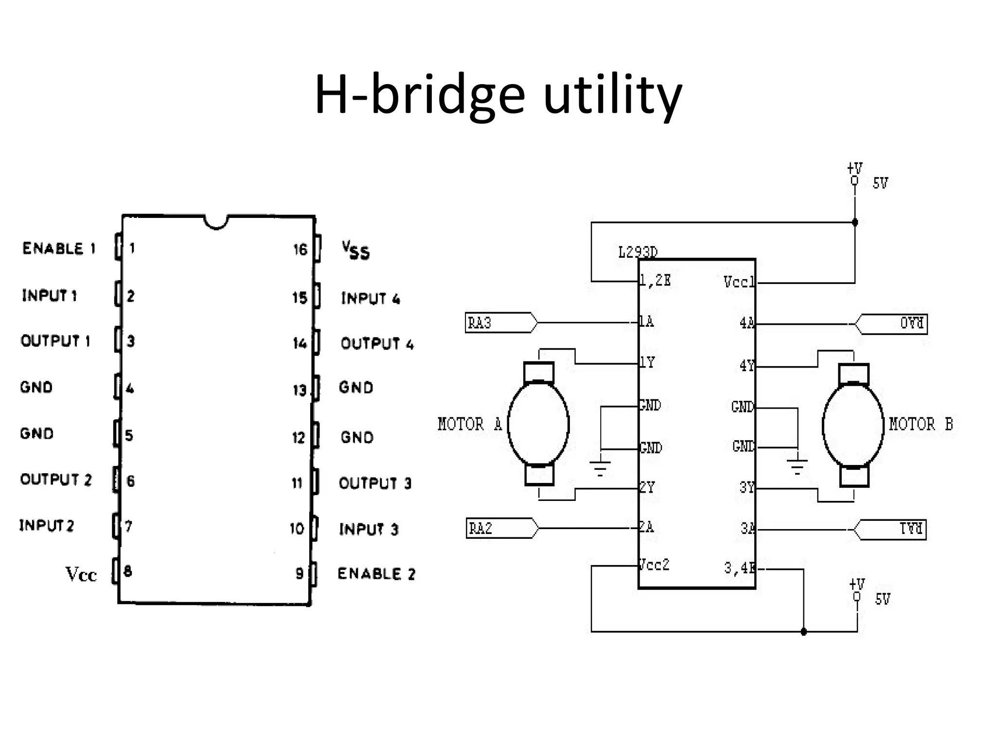
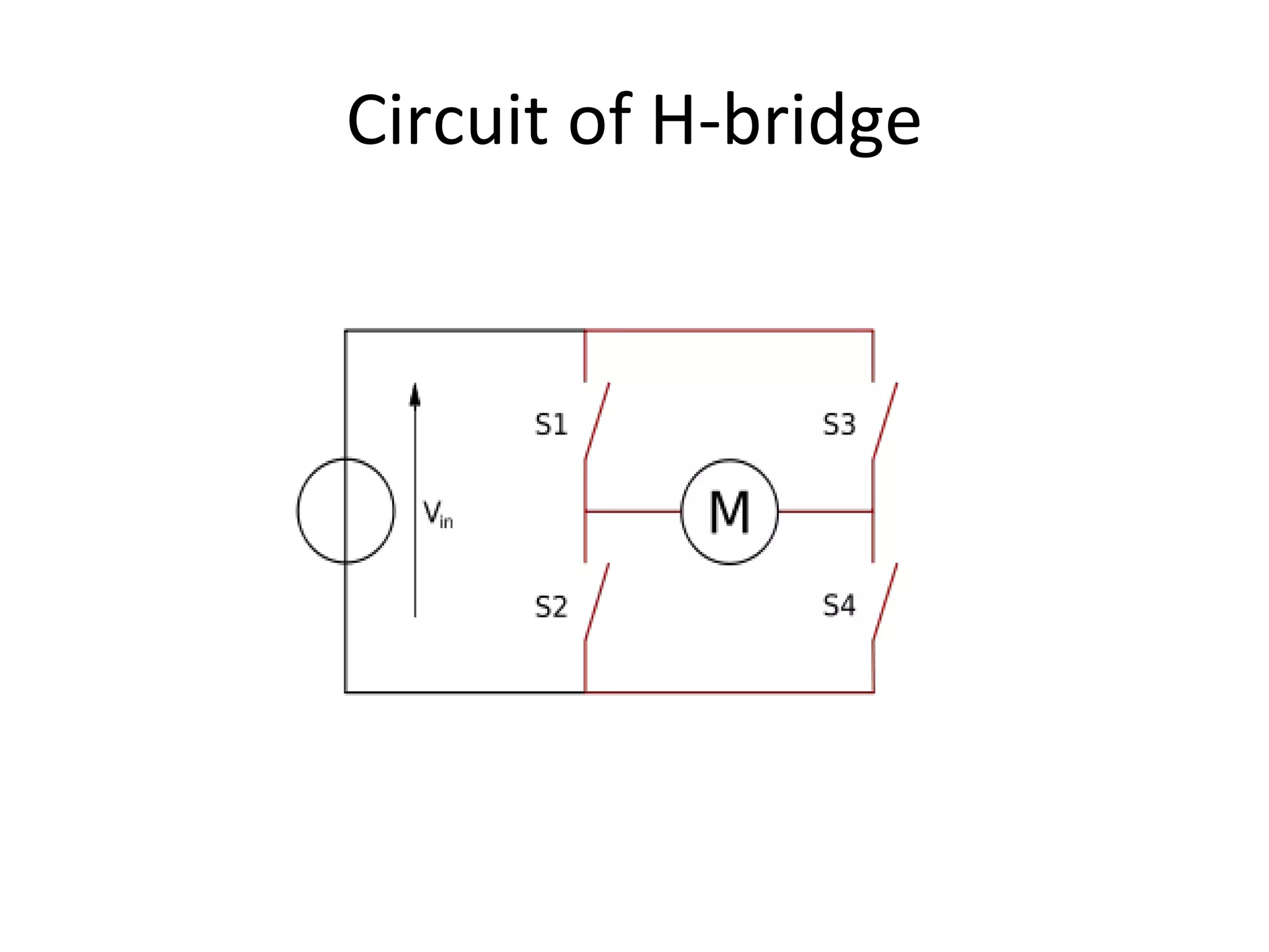
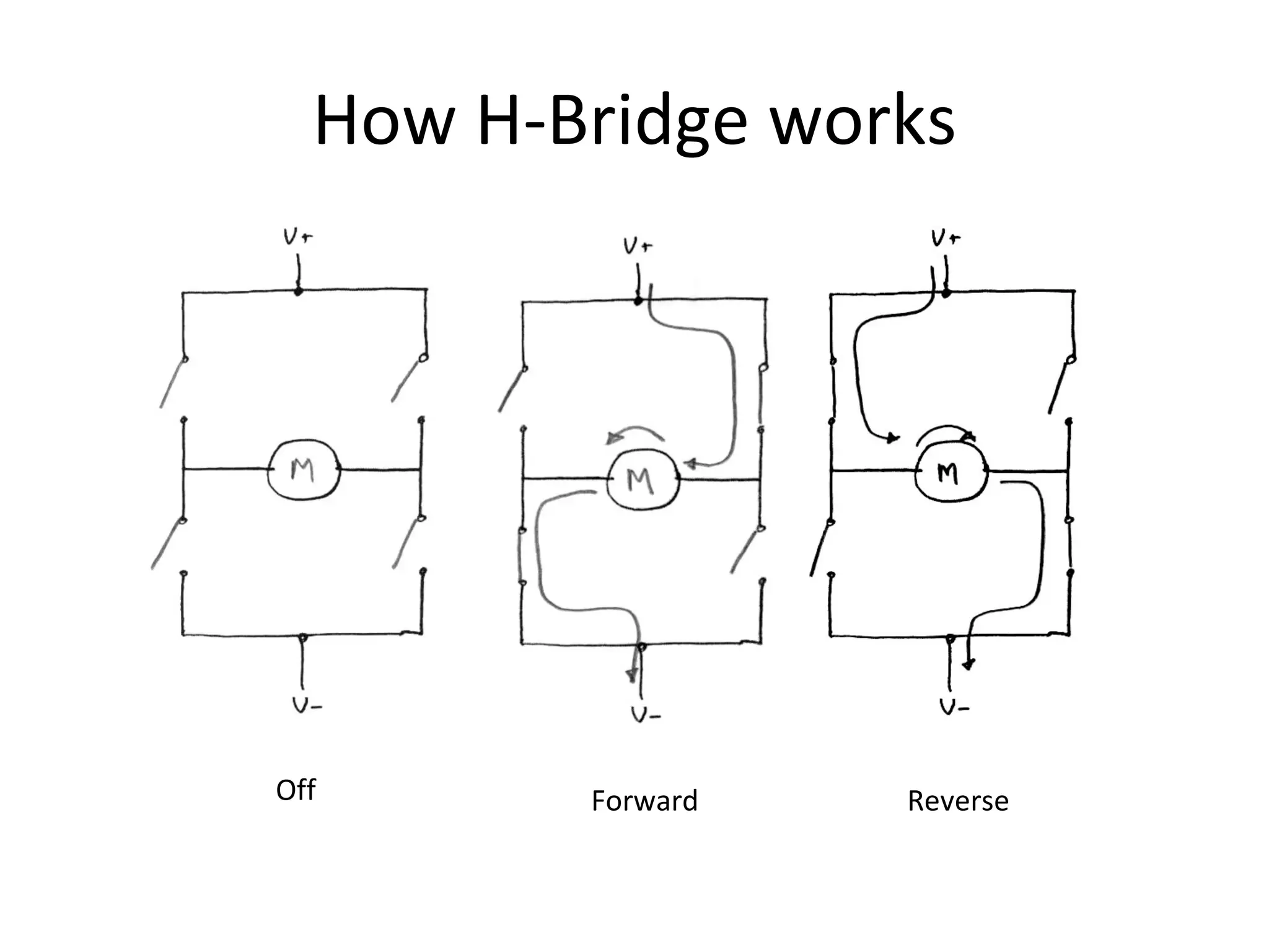
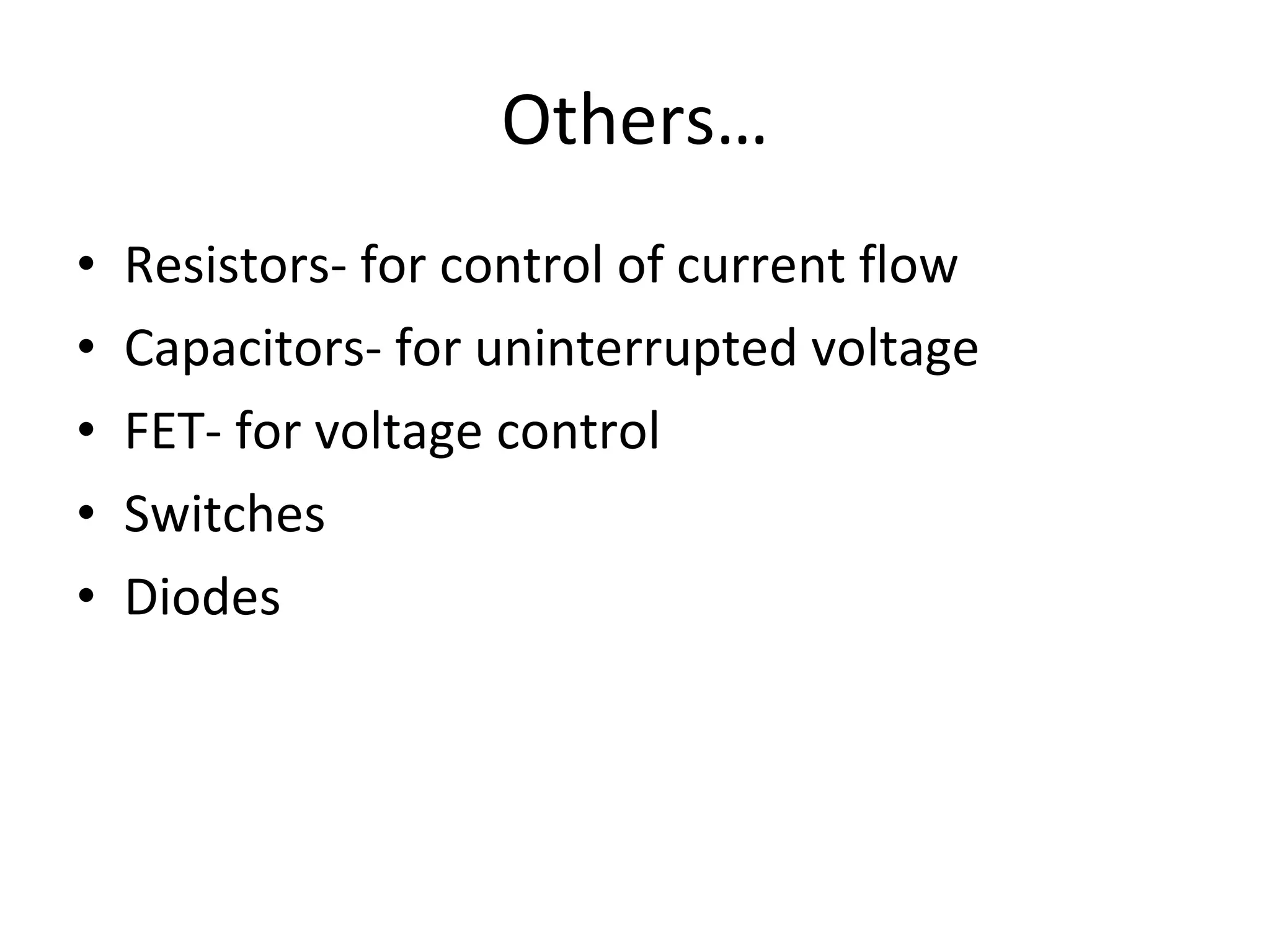
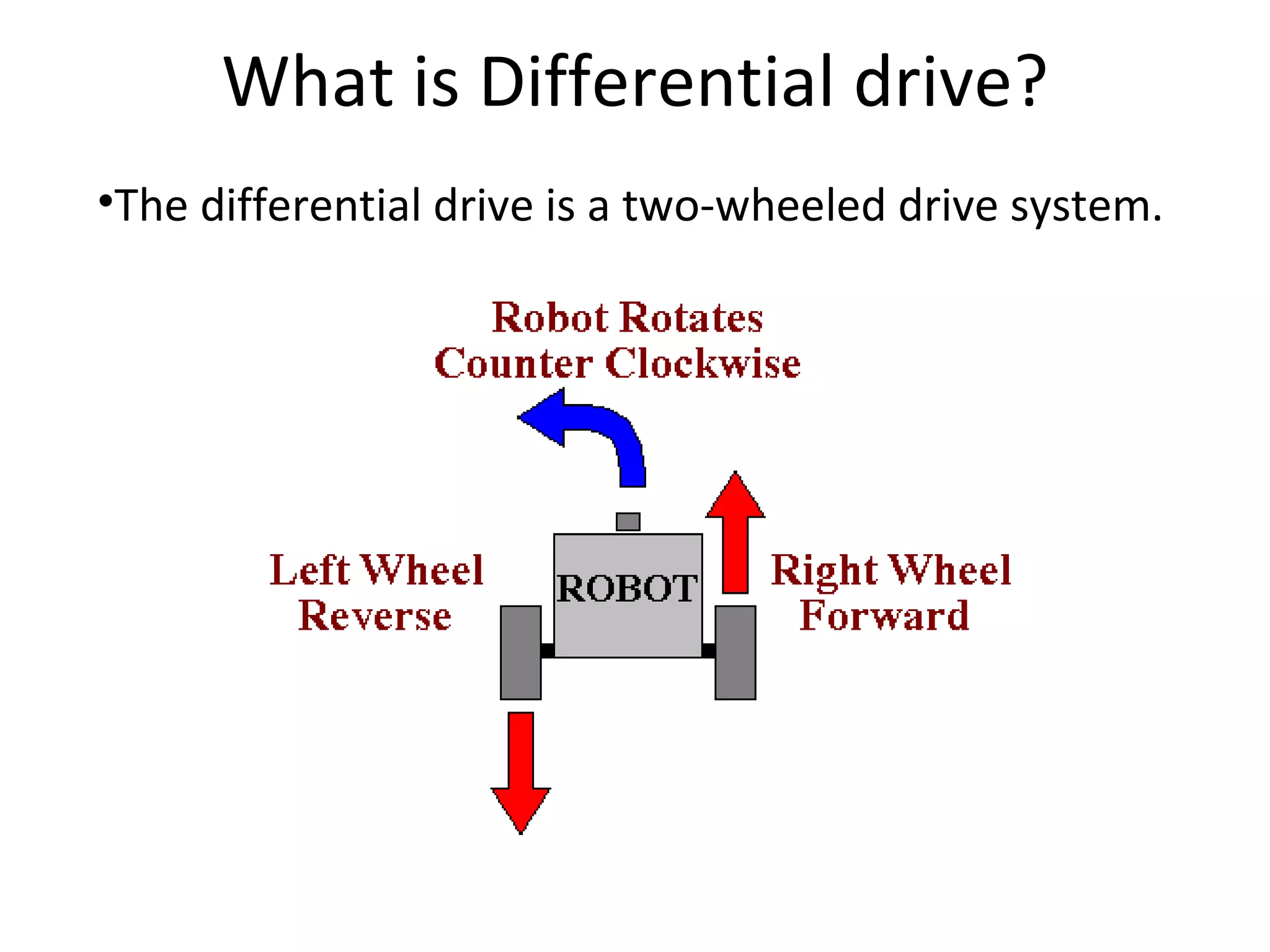
Minor project OIST  Electronics & Communication Group members: Aamir Hussain Abhikalp Gupta Alind Trivedi Anuj Koshti Bhrigu Raj Sharma
Prime Focus- Electronic components and circuitry involved Mechanical aspect Programming part
 
Electronic components Atmega32 microcontroller Crystal oscillator  Resistors  capacitors Diode  Drum  switches  H-bridge
Atmega32 Microcontroller
Key features…   8-bit Microcontroller Up to 1 MIPS Throughput at 16MHz On-chip Analog Comparator Operating Voltages  - 4.5-5.5V for ATmega32 Speed Grades  - 0-16 MHz for ATmega32
Utility  It is being used to operate the two motors Led’s  The required programming is loaded in the flash memory, according to which the movement is controlled
Crystal oscillator
Utility  Operates from 0 to 16 mhz. Provides the operating frequency for operation of microcontroller
H-bridge Enables a voltage to be applied across a load in either direction.  These circuits are often used in robotics and other applications to allow DC motors to run forwards and backwards.
H-bridge utility
Circuit of H-bridge
The two basic states of an H bridge
How H-Bridge works Off Forward Reverse
The following table summarizes operation, with S1-S4 corresponding to the diagram above. ACTION OF MOTOR S1 S2 S3 S4 Result 1 0 0 1 Motor moves right 0 1 1 0 Motor moves left 0 1 0 1 Motor brakes 1 0 1 0 Motor brakes
Others… Resistors- for control of current flow Capacitors- for uninterrupted voltage FET- for voltage control  Switches  Diodes
 
Actuators Actuators are mechanical devices which converts energy into motion The energy can be hydraulic, pneumatic or electric. In order to avoid the complexity we have chosen dc motor as actuator.
Parameters for selecting a motor Revolution per minute of shaft (rpm) Velocity of wheel Torque Power Voltage Current
RPM of Motor rpm of motor is defined as speed of the shaft without any load The rpm depends on the load The rpm is inversely proportional to torque.
Velocity It is the rotating speed of the wheel  Depends on the rpm & radius of the wheel. V =2*∏*r* ω For  a constant wheel radius, rpm can be used to control the velocity.
Torque Torque  α  (1 / rotational speed or rpm) On increasing the torque rpm will decrease & vice versa Having a small load on robot we choose a motor having less torque & more speed
Power Motor Power = Torque * rpm Required power = Force * velocity Required power will depends on  mass of robot  radius of wheel To drive robot efficiently:- Motor power > Required power
Voltage  DC motors are non polarized i.e. on reversing the polarity  the direction of rotation of wheel changes. Torque is directly proportional to applied voltage.
Current The operating current is the average current drawn by the motor which is required to drive the robot. To turn the wheel clockwise or anticlockwise, the direction of current is reversed which is done through H-bridge.
Selection of motor With all parameters including rpm, velocity, torque, power, current and voltage required to drive the motor efficiently a geared dc motor of following specifications is selected: 100RPM 9V DC with Gearbox 6mm shaft diameter with internal hole 125gm weight 1.2kgcm torque No-load current = 60 mA(Max), Load current = 300 mA(Max)
 
What is Differential drive? The differential drive is a two-wheeled drive system. 
The drive wheels are usually placed on each side of the robot and toward the front
Non driven wheel (metal ball)
Pros: Simplicity  Effective for plane surfaces Cost Effective Power Efficient
 
Programming …………….. For programming software used: Win AVR AVR studio 4 PL2303 USB driver USB programmer
Why AVR studio 4…………? AVR Studio 4 includes a debugger that supports  run control  source and instruction-level stepping  Registers  I/O views  target configuration and management
Standard program This program is made on AVR STUDIO 4 in the high level language (user friendly language)  which includes libraries for the compiling  and designing of program. #include  <avr/io.h>  int  main()  {  Step  1     Set  pin2  (PD0)  and  pin3  (PD1)  as  output  pin;  Step  2     Set  pin15  (PB1)  as  output  pin;  Step  3     Send  0  at  PD0  and  1  at  PD1;  Step  4     Send  1  at  PB1;  While(1)  {  //do  any  job  here } Return  0; }
Sample program This program is for the forward movement of this programmable moving robot. #include<avr/io.h> #include<util/delay.h> #include<compat/deprecated.h> int main() {    DDRC=0b11111111;//data direction register c is initialised by binary value while(1) { sbi(PORTC,1); //sets a bit of portc of ATMEGA32  sbi(PORTC,2); //sets a bit of portc of ATMEGA32  } return(0); }
Thank you All the glory in the world can be achieved by only………………………. …………………………… beginning…..

My minor project

  • 1.
    Minor project OIST Electronics & Communication Group members: Aamir Hussain Abhikalp Gupta Alind Trivedi Anuj Koshti Bhrigu Raj Sharma
  • 2.
    Prime Focus- Electroniccomponents and circuitry involved Mechanical aspect Programming part
  • 3.
  • 4.
    Electronic components Atmega32microcontroller Crystal oscillator Resistors capacitors Diode Drum switches H-bridge
  • 5.
  • 6.
    Key features…  8-bit Microcontroller Up to 1 MIPS Throughput at 16MHz On-chip Analog Comparator Operating Voltages  - 4.5-5.5V for ATmega32 Speed Grades  - 0-16 MHz for ATmega32
  • 7.
    Utility Itis being used to operate the two motors Led’s The required programming is loaded in the flash memory, according to which the movement is controlled
  • 8.
  • 9.
    Utility Operatesfrom 0 to 16 mhz. Provides the operating frequency for operation of microcontroller
  • 10.
    H-bridge Enables avoltage to be applied across a load in either direction. These circuits are often used in robotics and other applications to allow DC motors to run forwards and backwards.
  • 11.
  • 12.
  • 13.
    The two basicstates of an H bridge
  • 14.
    How H-Bridge worksOff Forward Reverse
  • 15.
    The following tablesummarizes operation, with S1-S4 corresponding to the diagram above. ACTION OF MOTOR S1 S2 S3 S4 Result 1 0 0 1 Motor moves right 0 1 1 0 Motor moves left 0 1 0 1 Motor brakes 1 0 1 0 Motor brakes
  • 16.
    Others… Resistors- forcontrol of current flow Capacitors- for uninterrupted voltage FET- for voltage control Switches Diodes
  • 17.
  • 18.
    Actuators Actuators aremechanical devices which converts energy into motion The energy can be hydraulic, pneumatic or electric. In order to avoid the complexity we have chosen dc motor as actuator.
  • 19.
    Parameters for selectinga motor Revolution per minute of shaft (rpm) Velocity of wheel Torque Power Voltage Current
  • 20.
    RPM of Motorrpm of motor is defined as speed of the shaft without any load The rpm depends on the load The rpm is inversely proportional to torque.
  • 21.
    Velocity It isthe rotating speed of the wheel Depends on the rpm & radius of the wheel. V =2*∏*r* ω For a constant wheel radius, rpm can be used to control the velocity.
  • 22.
    Torque Torque α (1 / rotational speed or rpm) On increasing the torque rpm will decrease & vice versa Having a small load on robot we choose a motor having less torque & more speed
  • 23.
    Power Motor Power= Torque * rpm Required power = Force * velocity Required power will depends on mass of robot radius of wheel To drive robot efficiently:- Motor power > Required power
  • 24.
    Voltage DCmotors are non polarized i.e. on reversing the polarity the direction of rotation of wheel changes. Torque is directly proportional to applied voltage.
  • 25.
    Current The operatingcurrent is the average current drawn by the motor which is required to drive the robot. To turn the wheel clockwise or anticlockwise, the direction of current is reversed which is done through H-bridge.
  • 26.
    Selection of motorWith all parameters including rpm, velocity, torque, power, current and voltage required to drive the motor efficiently a geared dc motor of following specifications is selected: 100RPM 9V DC with Gearbox 6mm shaft diameter with internal hole 125gm weight 1.2kgcm torque No-load current = 60 mA(Max), Load current = 300 mA(Max)
  • 27.
  • 28.
    What is Differentialdrive? The differential drive is a two-wheeled drive system. 
  • 29.
    The drive wheelsare usually placed on each side of the robot and toward the front
  • 30.
    Non driven wheel(metal ball)
  • 31.
    Pros: Simplicity Effective for plane surfaces Cost Effective Power Efficient
  • 32.
  • 33.
    Programming …………….. Forprogramming software used: Win AVR AVR studio 4 PL2303 USB driver USB programmer
  • 34.
    Why AVR studio4…………? AVR Studio 4 includes a debugger that supports run control source and instruction-level stepping Registers I/O views target configuration and management
  • 35.
    Standard program Thisprogram is made on AVR STUDIO 4 in the high level language (user friendly language) which includes libraries for the compiling and designing of program. #include  <avr/io.h> int  main() { Step  1    Set  pin2  (PD0)  and  pin3  (PD1)  as  output  pin; Step  2    Set  pin15  (PB1)  as  output  pin; Step  3    Send  0  at  PD0  and  1  at  PD1; Step  4    Send  1  at  PB1; While(1) { //do  any  job  here } Return  0; }
  • 36.
    Sample program Thisprogram is for the forward movement of this programmable moving robot. #include<avr/io.h> #include<util/delay.h> #include<compat/deprecated.h> int main() {   DDRC=0b11111111;//data direction register c is initialised by binary value while(1) { sbi(PORTC,1); //sets a bit of portc of ATMEGA32 sbi(PORTC,2); //sets a bit of portc of ATMEGA32 } return(0); }
  • 37.
    Thank you Allthe glory in the world can be achieved by only………………………. …………………………… beginning…..