Download as PDF, PPTX

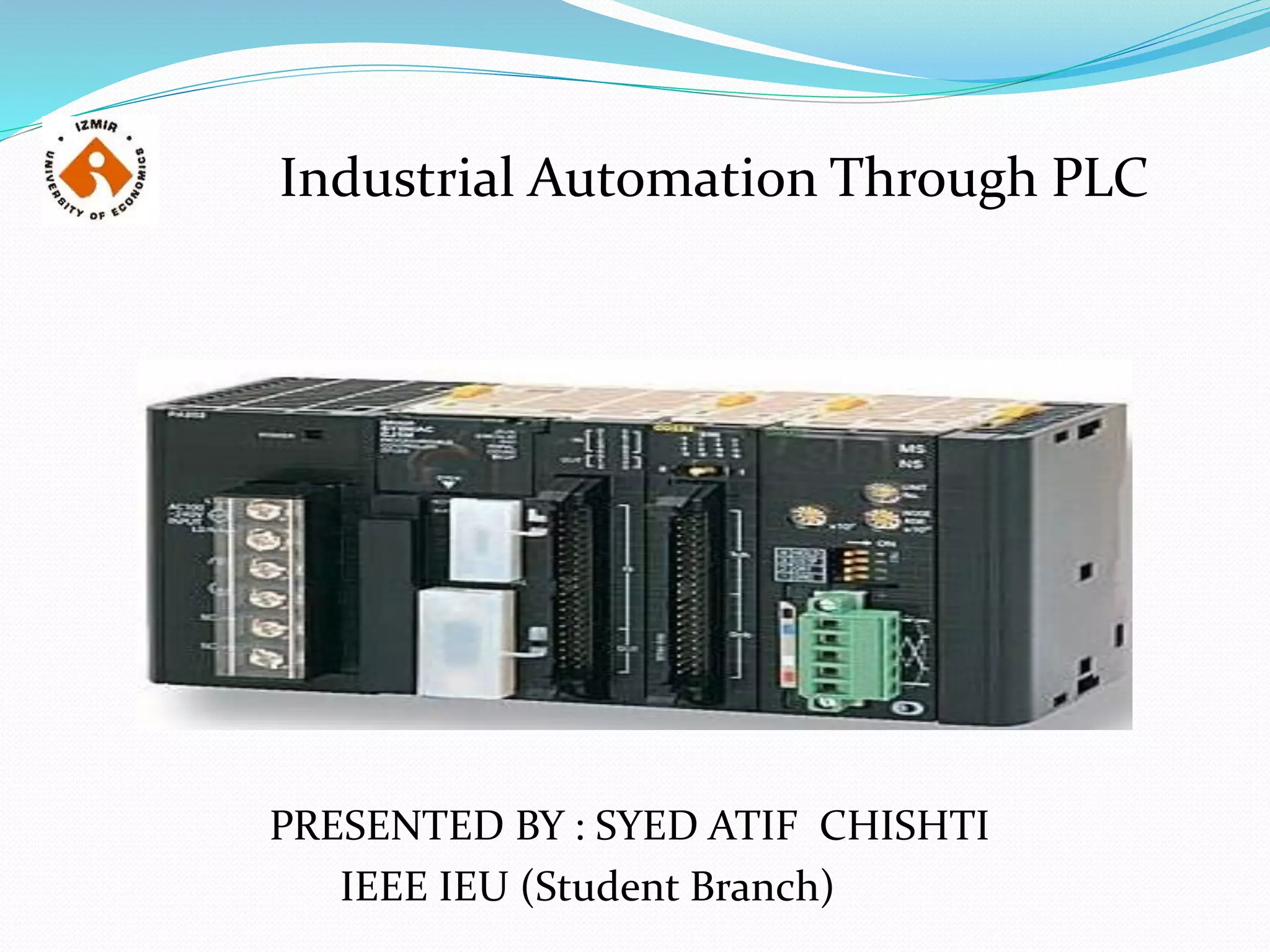
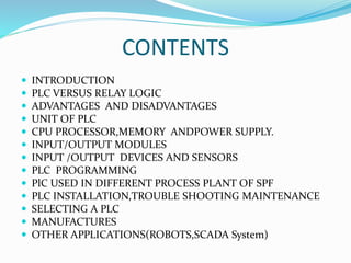
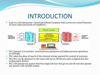
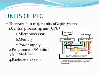
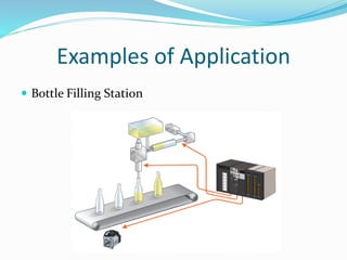
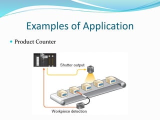
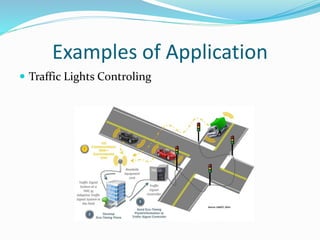
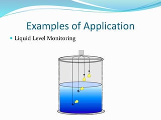
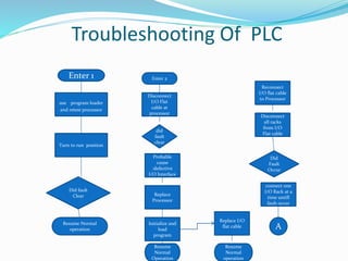
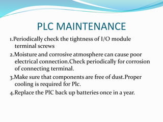
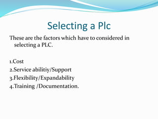


This document provides an overview of industrial automation through programmable logic controllers (PLCs). It discusses what a PLC is and how it works, including the main units of a PLC system like the central processing unit, memory, input/output modules, and programming. The document also covers advantages of PLCs over relay logic, common PLC applications, installation/maintenance, troubleshooting, and selecting a PLC. It aims to introduce the basic concepts of PLCs and how they are used for industrial automation.