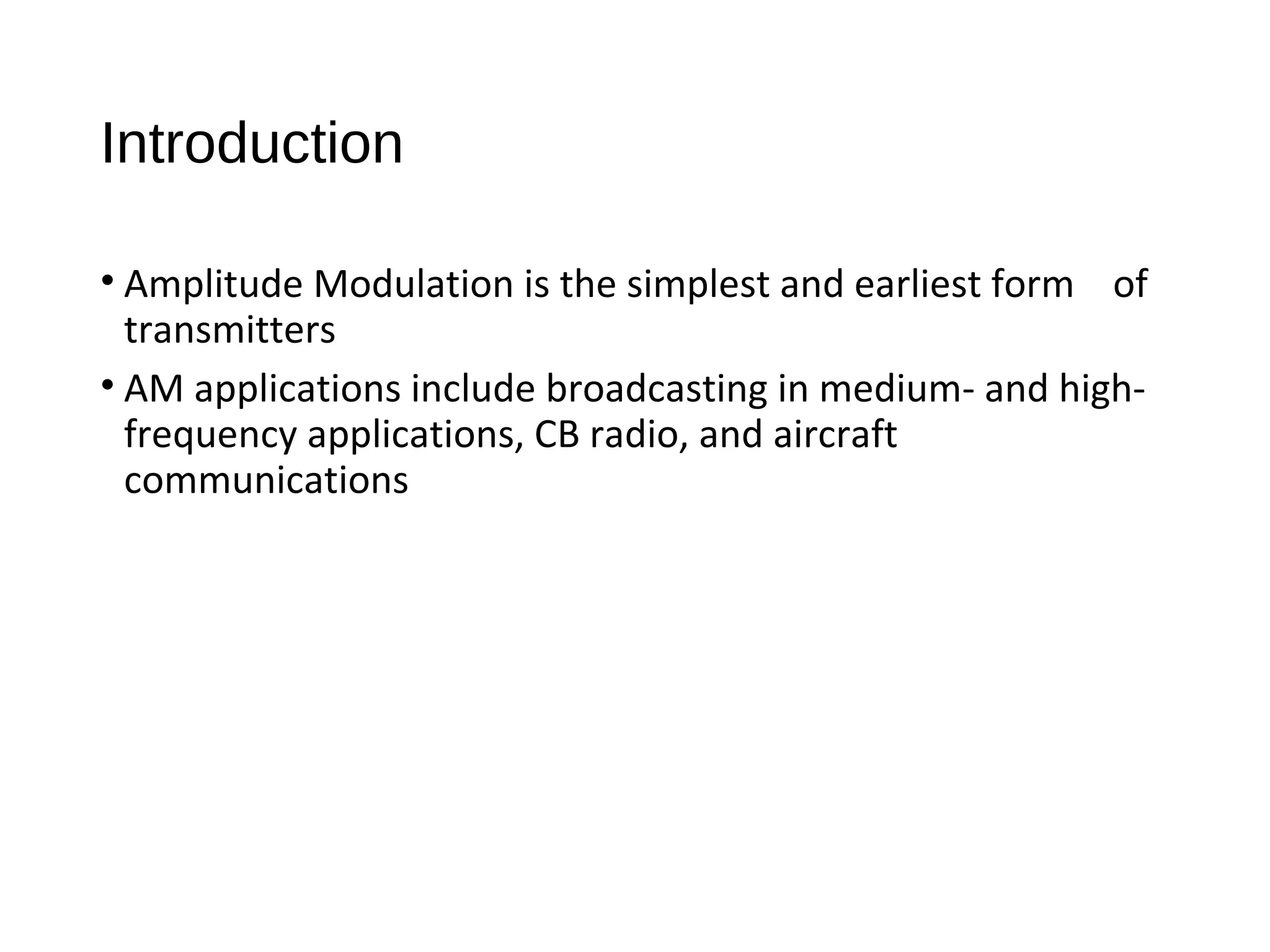
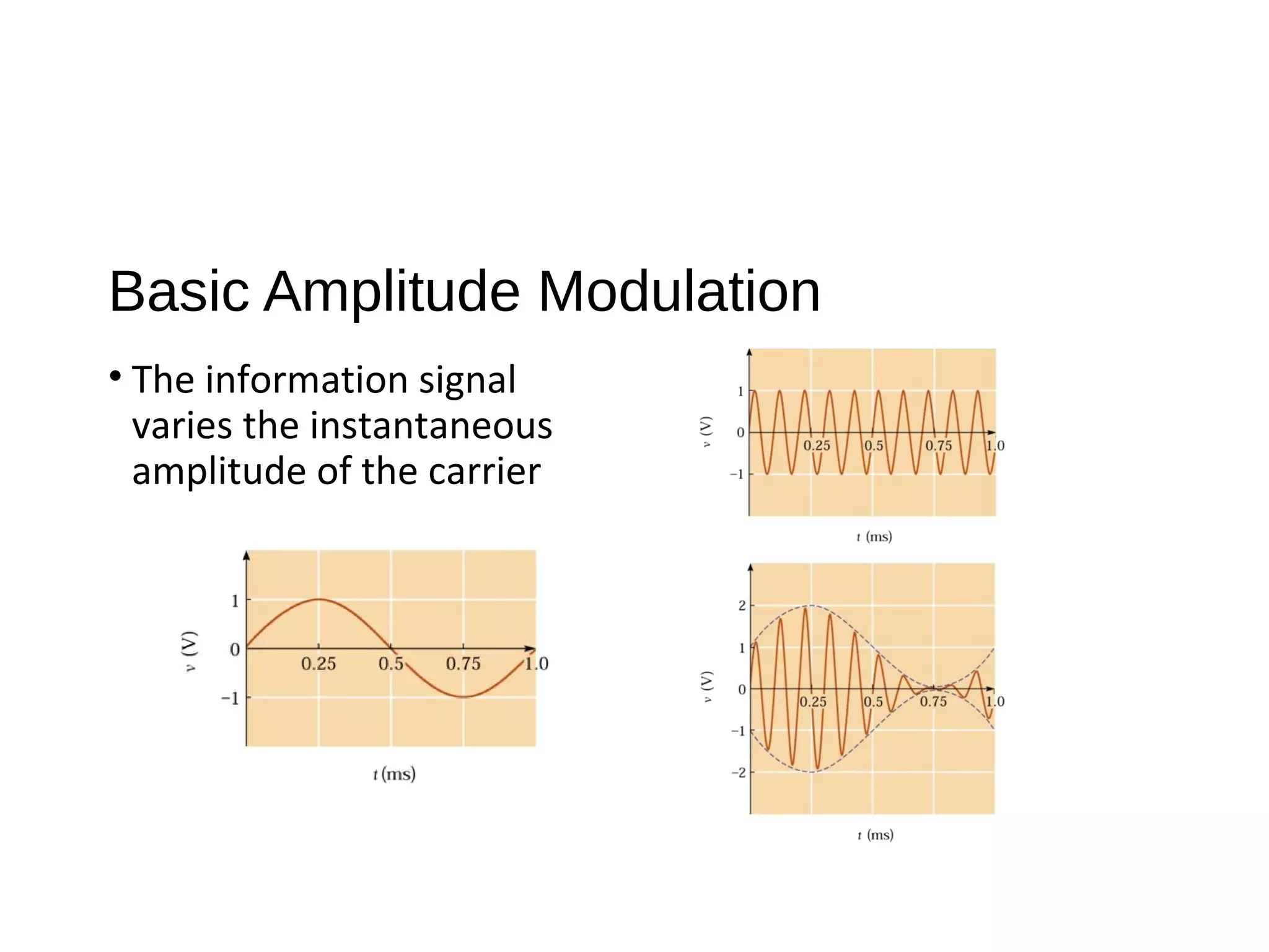
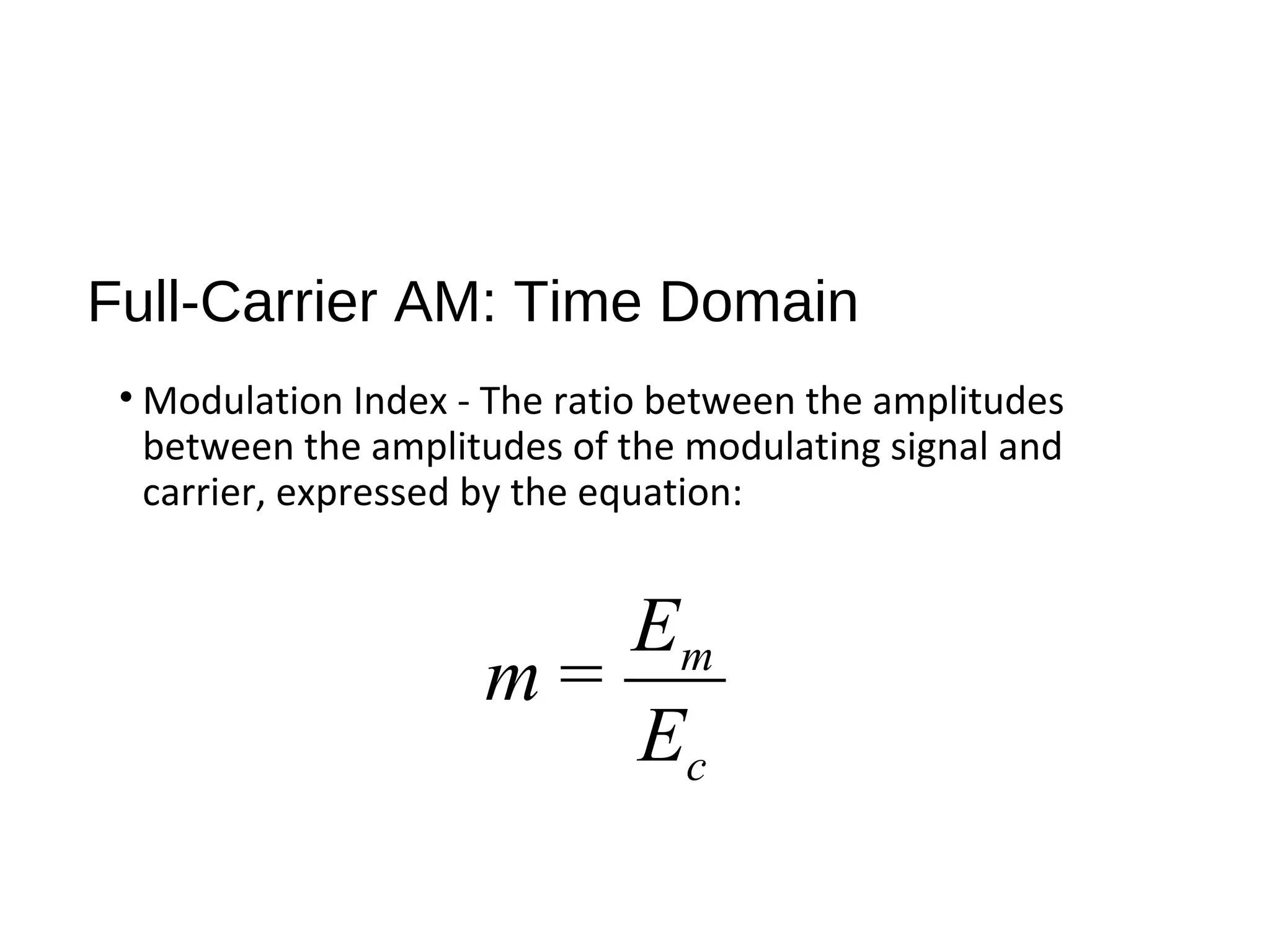
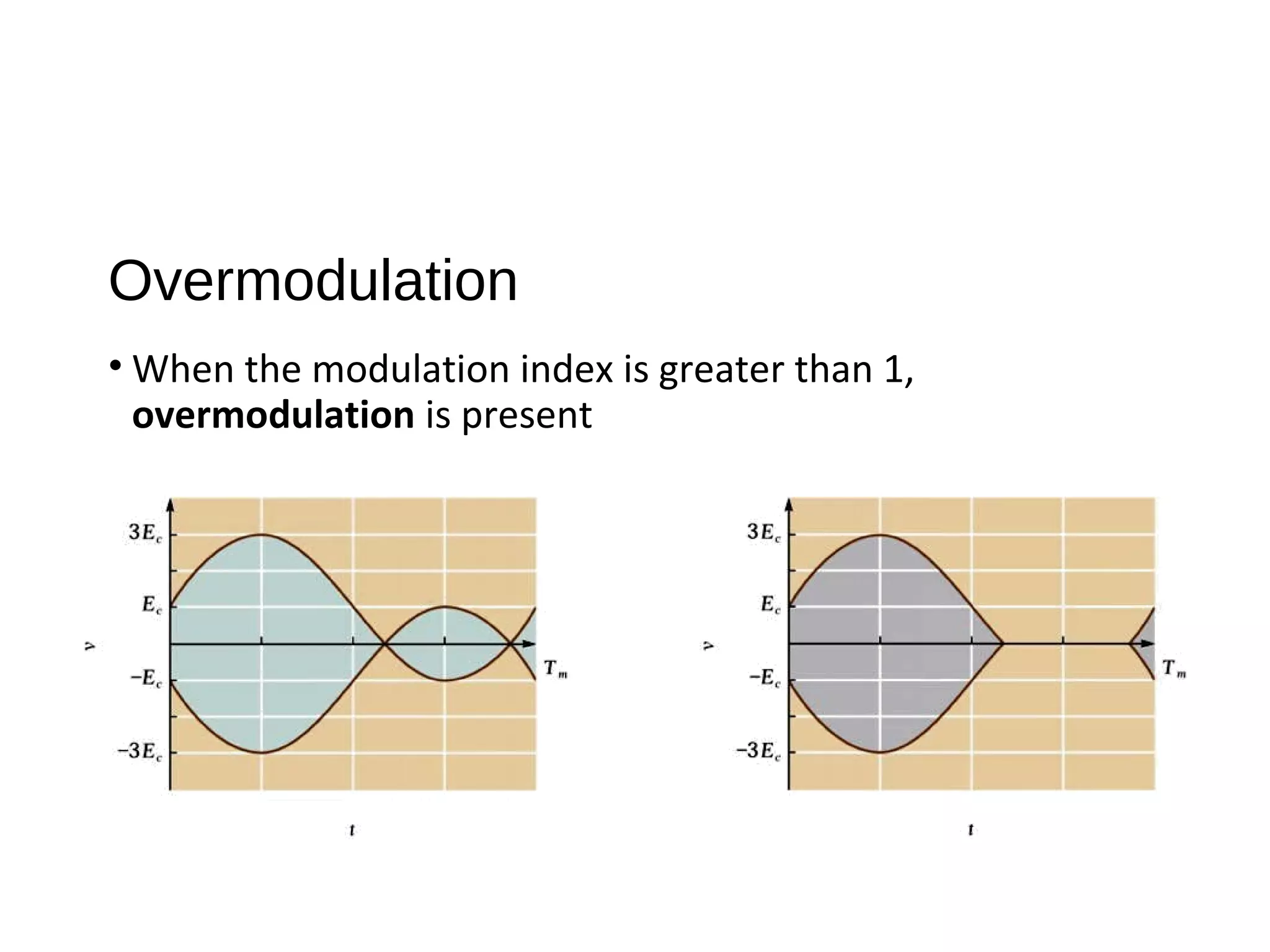
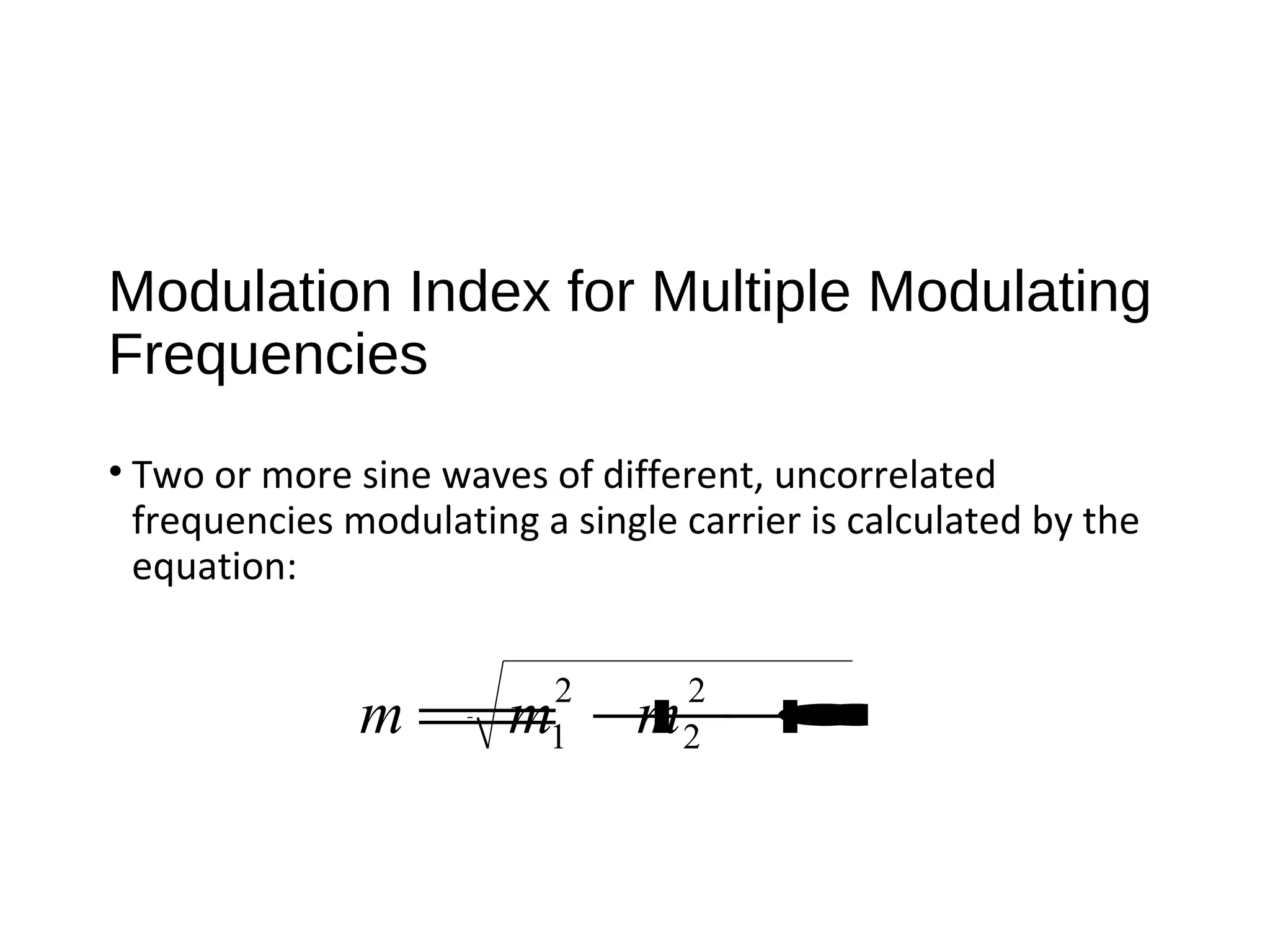
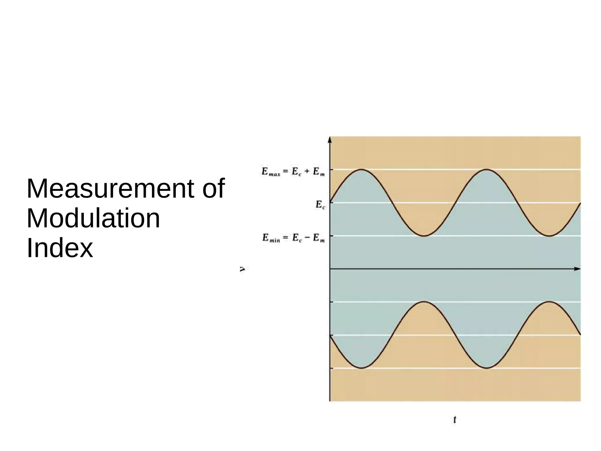
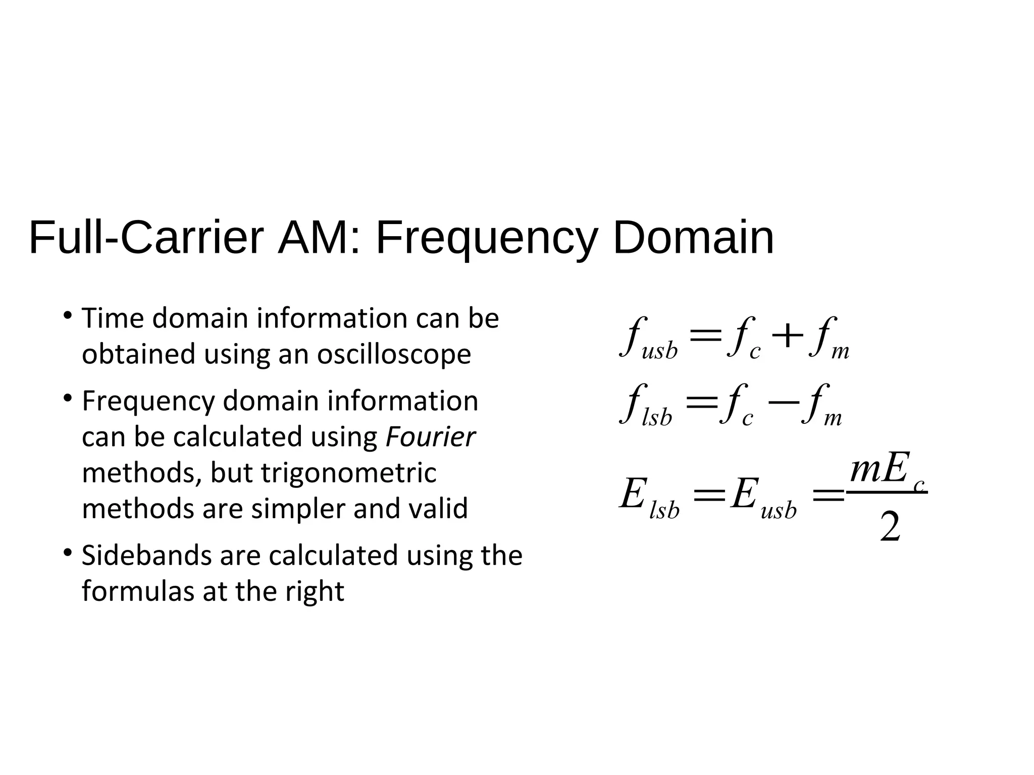
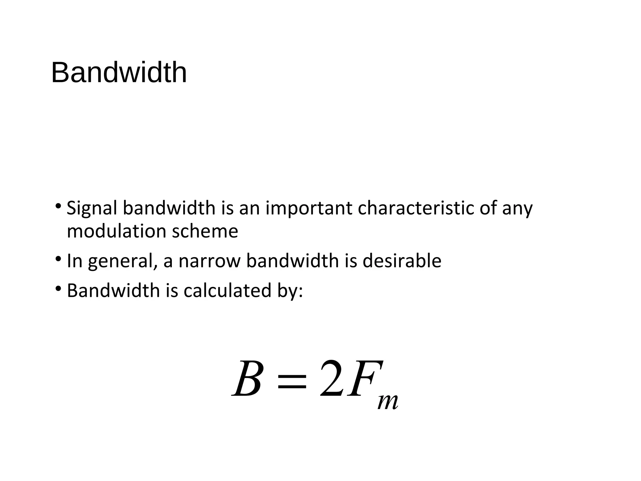
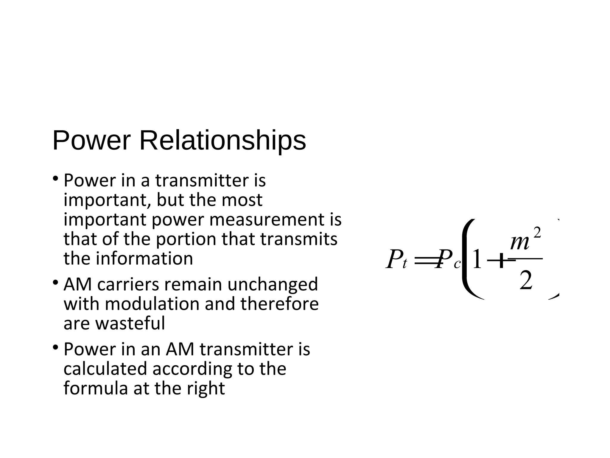
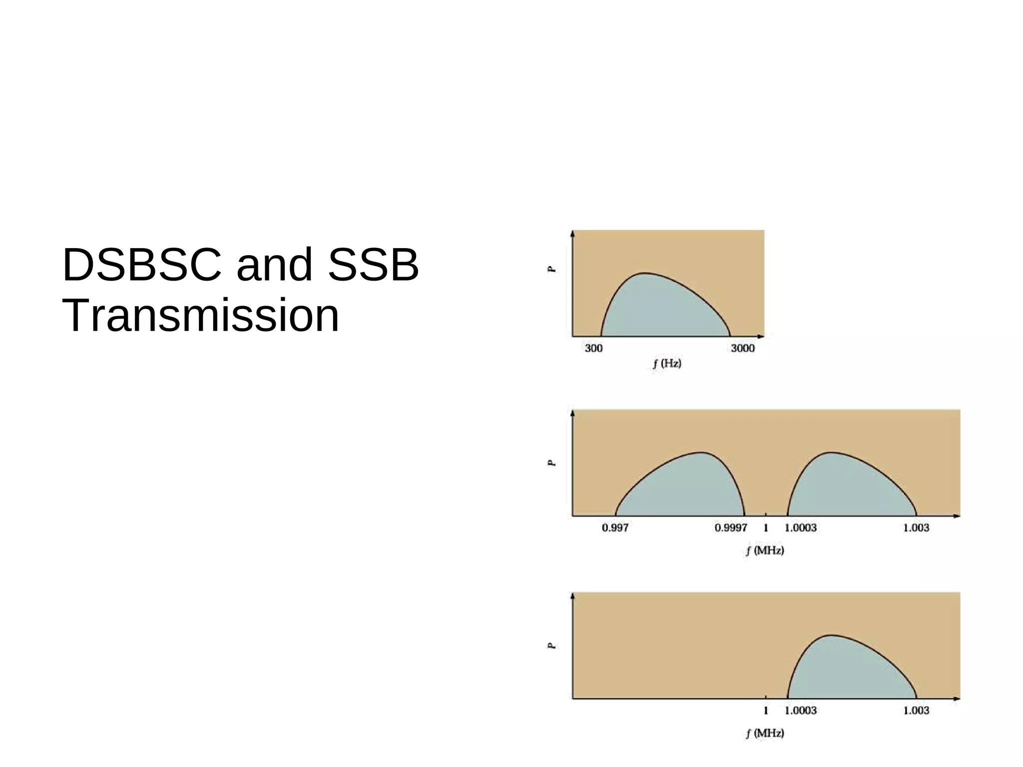
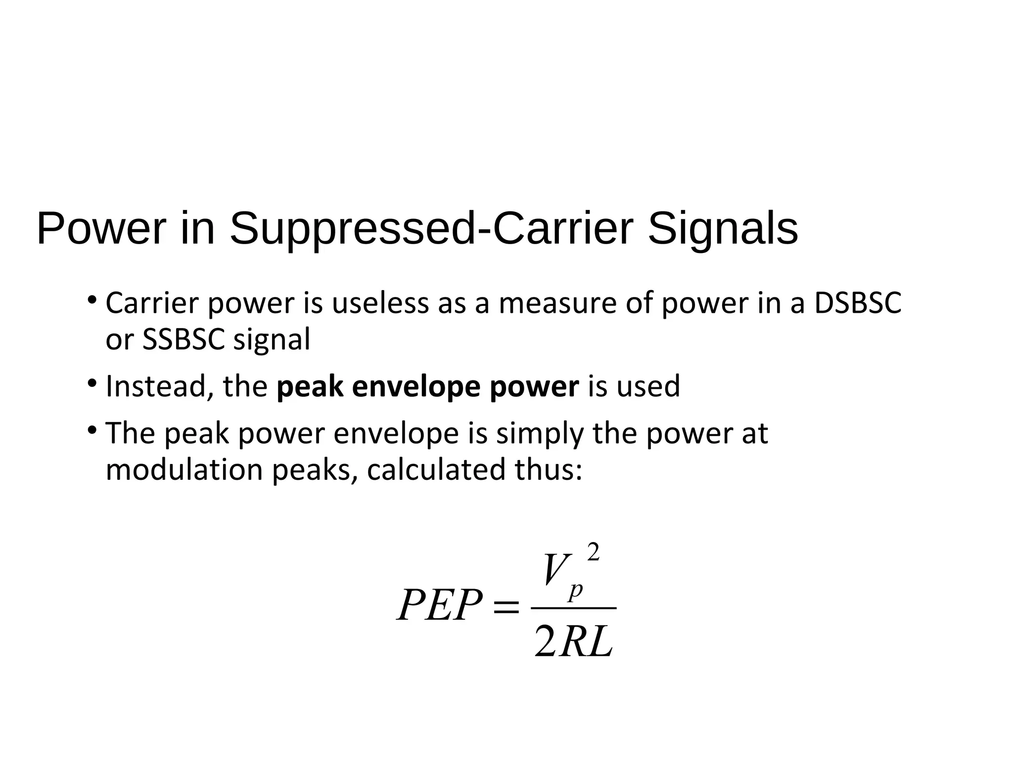
Amplitude Modulation
Introduction
• Amplitude Modulation is the simplest and earliest form of
transmitters
• AM applications include broadcasting in medium- and high-
frequency applications, CB radio, and aircraft
communications
Basic Amplitude Modulation
• The information signal
varies the instantaneous
amplitude of the carrier
AM Characteristics
• AM is a nonlinear process
• Sum and difference frequencies are created that carry the
information
Full-Carrier AM: Time Domain
• Modulation Index - The ratio between the amplitudes
between the amplitudes of the modulating signal and
carrier, expressed by the equation:
c
m
E
E
m =
Overmodulation
• When the modulation index is greater than 1,
overmodulation is present
Modulation Index for Multiple Modulating
Frequencies
• Two or more sine waves of different, uncorrelated
frequencies modulating a single carrier is calculated by the
equation:
m =m1
2
+m2
2
+•••
Measurement of
Modulation
Index
Full-Carrier AM: Frequency Domain
• Time domain information can be
obtained using an oscilloscope
• Frequency domain information
can be calculated using Fourier
methods, but trigonometric
methods are simpler and valid
• Sidebands are calculated using the
formulas at the right
fusb = fc + fm
flsb = fc − fm
Elsb =Eusb =
mEc
2
Bandwidth
• Signal bandwidth is an important characteristic of any
modulation scheme
• In general, a narrow bandwidth is desirable
• Bandwidth is calculated by:
mFB 2=
Power Relationships
• Power in a transmitter is
important, but the most
important power measurement is
that of the portion that transmits
the information
• AM carriers remain unchanged
with modulation and therefore
are wasteful
• Power in an AM transmitter is
calculated according to the
formula at the right
Pt =Pc 1+
m2
2






Quadrature AM and AM Stereo
• Two carriers generated at the same frequency but 90º out of
phase with each other allow transmission of two separate signals
• This approach is known as Quadrature AM (QUAM or QAM)
• Recovery of the two signals is accomplished by synchronous
detection by two balanced modulators
Quadrature Operation
Suppressed-Carrier AM
• Full-carrier AM is simple but not efficient
• Removing the carrier before power amplification allows full
transmitter power to be applied to the sidebands
• Removing the carrier from a fully modulated AM systems
results in a double-sideband suppressed-carrier
transmission
Suppressed-Carrier Signal
Single-Sideband AM
• The two sidebands of an AM signal are mirror images of
one another
• As a result, one of the sidebands is redundant
• Using single-sideband suppressed-carrier transmission
results in reduced bandwidth and therefore twice as many
signals may be transmitted in the same spectrum allotment
• Typically, a 3dB improvement in signal-to-noise ratio is
achieved as a result of SSBSC
DSBSC and SSB
Transmission
Power in Suppressed-Carrier Signals
• Carrier power is useless as a measure of power in a DSBSC
or SSBSC signal
• Instead, the peak envelope power is used
• The peak power envelope is simply the power at
modulation peaks, calculated thus:
RL
V
PEP p
2
2
=

Amplitude modulation

  • 1.
  • 2.
    Introduction • Amplitude Modulationis the simplest and earliest form of transmitters • AM applications include broadcasting in medium- and high- frequency applications, CB radio, and aircraft communications
  • 3.
    Basic Amplitude Modulation •The information signal varies the instantaneous amplitude of the carrier
  • 4.
    AM Characteristics • AMis a nonlinear process • Sum and difference frequencies are created that carry the information
  • 5.
    Full-Carrier AM: TimeDomain • Modulation Index - The ratio between the amplitudes between the amplitudes of the modulating signal and carrier, expressed by the equation: c m E E m =
  • 6.
    Overmodulation • When themodulation index is greater than 1, overmodulation is present
  • 7.
    Modulation Index forMultiple Modulating Frequencies • Two or more sine waves of different, uncorrelated frequencies modulating a single carrier is calculated by the equation: m =m1 2 +m2 2 +•••
  • 8.
  • 9.
    Full-Carrier AM: FrequencyDomain • Time domain information can be obtained using an oscilloscope • Frequency domain information can be calculated using Fourier methods, but trigonometric methods are simpler and valid • Sidebands are calculated using the formulas at the right fusb = fc + fm flsb = fc − fm Elsb =Eusb = mEc 2
  • 10.
    Bandwidth • Signal bandwidthis an important characteristic of any modulation scheme • In general, a narrow bandwidth is desirable • Bandwidth is calculated by: mFB 2=
  • 11.
    Power Relationships • Powerin a transmitter is important, but the most important power measurement is that of the portion that transmits the information • AM carriers remain unchanged with modulation and therefore are wasteful • Power in an AM transmitter is calculated according to the formula at the right Pt =Pc 1+ m2 2      
  • 12.
    Quadrature AM andAM Stereo • Two carriers generated at the same frequency but 90º out of phase with each other allow transmission of two separate signals • This approach is known as Quadrature AM (QUAM or QAM) • Recovery of the two signals is accomplished by synchronous detection by two balanced modulators
  • 13.
  • 14.
    Suppressed-Carrier AM • Full-carrierAM is simple but not efficient • Removing the carrier before power amplification allows full transmitter power to be applied to the sidebands • Removing the carrier from a fully modulated AM systems results in a double-sideband suppressed-carrier transmission
  • 15.
  • 16.
    Single-Sideband AM • Thetwo sidebands of an AM signal are mirror images of one another • As a result, one of the sidebands is redundant • Using single-sideband suppressed-carrier transmission results in reduced bandwidth and therefore twice as many signals may be transmitted in the same spectrum allotment • Typically, a 3dB improvement in signal-to-noise ratio is achieved as a result of SSBSC
  • 17.
  • 18.
    Power in Suppressed-CarrierSignals • Carrier power is useless as a measure of power in a DSBSC or SSBSC signal • Instead, the peak envelope power is used • The peak power envelope is simply the power at modulation peaks, calculated thus: RL V PEP p 2 2 =