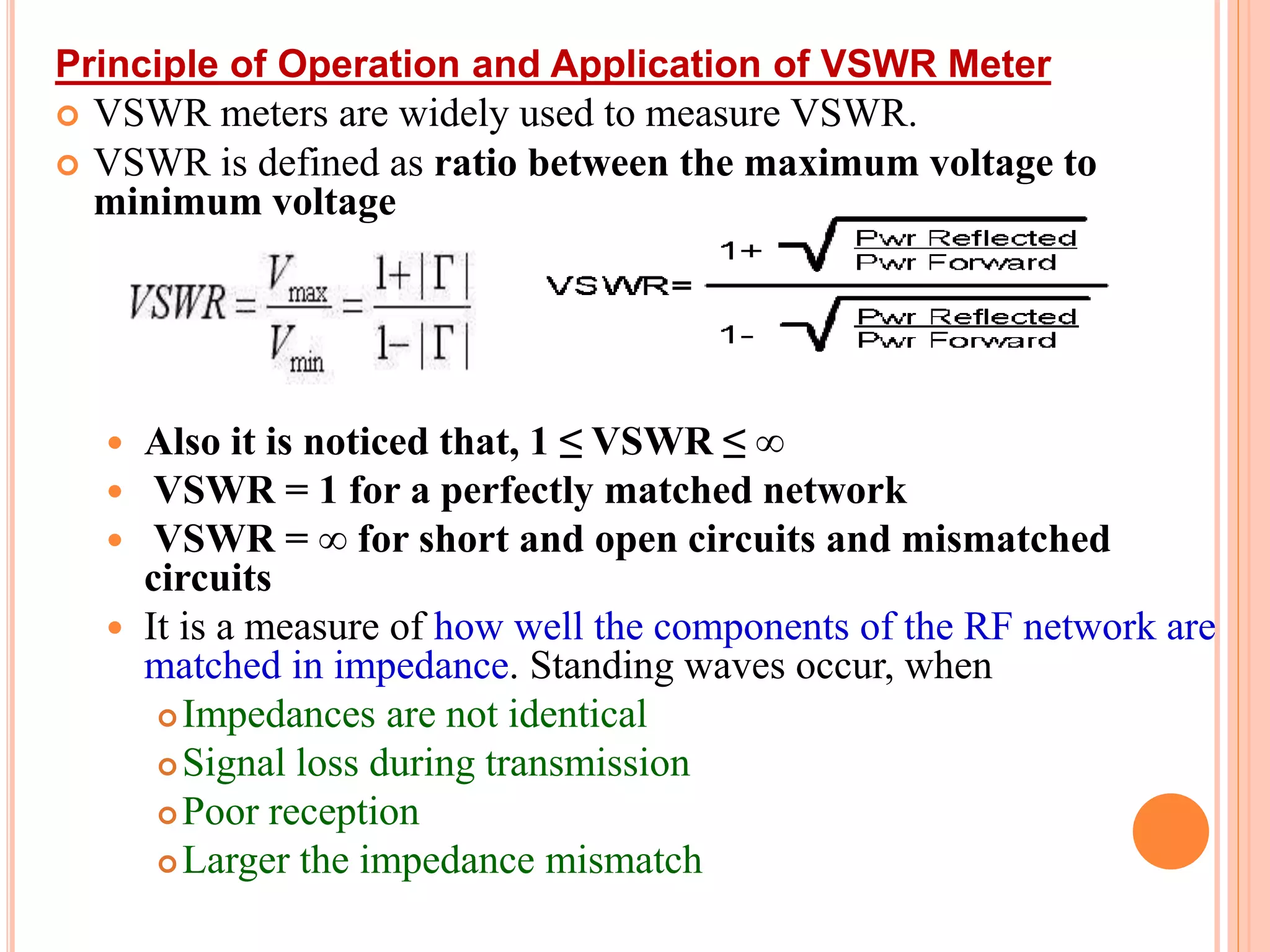
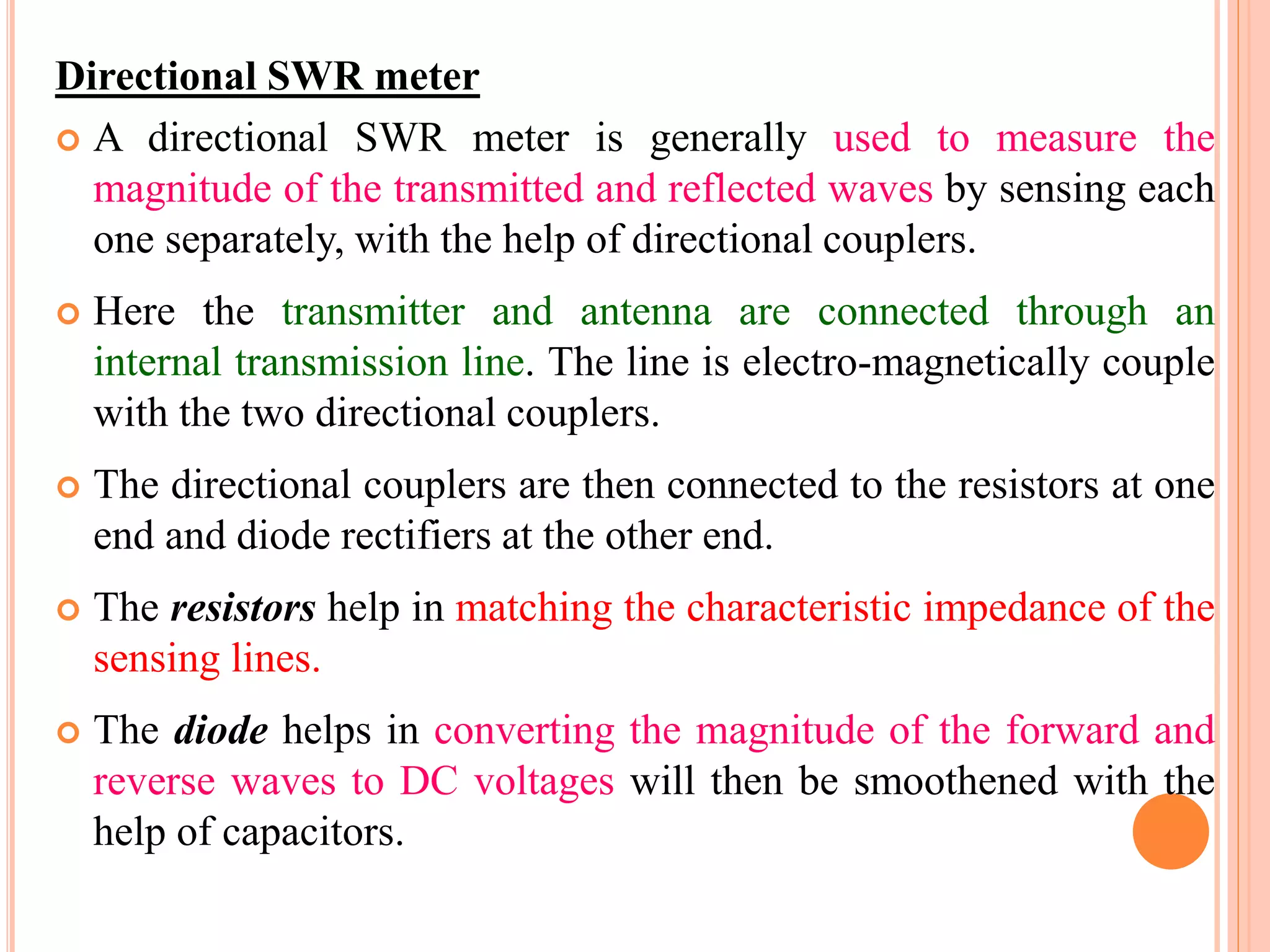
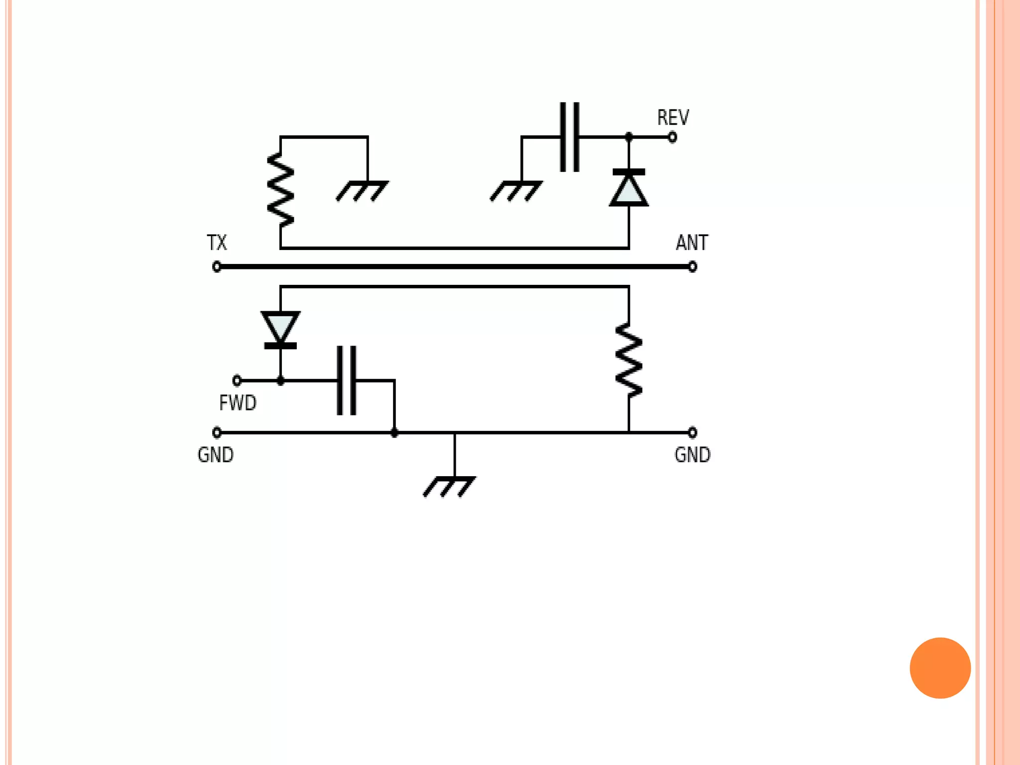
This document discusses voltage standing wave ratio (VSWR) meters, which are used to measure impedance matching and standing waves in microwave systems. It describes the principles of VSWR meters, including their construction with normal, expanded, and dB scales. Two common types are directional VSWR meters and SWR bridge circuits. Applications include laboratories, live broadcast systems, and medical equipment. Problems with VSWR meters are also noted, such as their inability to measure reactance and sensitivity to signal attenuation.
MicroStrip Antenna
Introduction .
Micro-Strip Antennas Types .
Micro-Strip Antennas Shapes .
Types of Substrates (Dielectric Media) .
Comparison of various types of flat profile printed antennas .
Advantages & DisAdvantages of MSAs .
Applications of MSAs .
Radiation patterns of MSAs .
How to Optimizing the Substrate Properties for Increased Bandwidth ?
Comparing the different feed techniques .
A Klystron is a vacuum tube that can be used either as a generator or as an amplifier or as an oscillator, at microwave frequencies.The Klystron is a linear beam device; that is, the electron flow is in a straight line focused by an axial magnetic field.
The attached narrated power point presentation attempts to explain the methods of computation of total power loss and system rise time in a fiber optic link. The material will be useful for KTU final year B Tech students who prepare for the subject EC 405, Optical Communications.
Satellite Link Design:
EIRP, Transmission Losses, Free-space transmission, System noise temperature and G/T ratio, Noise figure, Design of downlinks, Design of uplink, Design of specified C/N: combining C/N and C/I values in satellite links, Overall C/No, Link design procedure.
It is a digital representation of an analog signal that takes samples of the amplitude of the analog signal at regular intervals. The sampled analog data is changed to, and then represented by, binary data.
A wave analyzer is an instrument designed to measure relative amplitudes of single frequency components in a complex waveform. Basically, a wave instrument acts as a frequency selective voltmeter which is tuned to the frequency of one signal while rejecting all other signal components.
The Presentation includes Basics of Non - Uniform Quantization, Companding and different Pulse Code Modulation Techniques. Comparison of Various PCM techniques is done considering various Parameters in Communication Systems.
good for studentgood for studentgood for studentgood for studentgood for studentgood for studentgood for studentgood for studentgood for studentgood for studentgood for studentgood for studentgood for studentgood for studentgood for studentgood for student
When dealing with antennas, microwave radio frequency engineers have to deal with standing wave ratio. What is the voltage standing wave ratio and how is this parameter calculated?
In any radio system that includes a transmission line, the transmitter of the radio signal, the transmission line that transmits the signal, and the load of the radio signal have a characteristic impedance.
The transmitting and receiving systems usually used for amateur radio signals mostly have a characteristic impedance of 50 ohms, while the characteristic impedance in a cable television system is mostly 75 ohms.
When the characteristic impedances of all devices in this system are the same, the problem is not big. But if the characteristic impedance of the transmitter and the transmission line are both 50 ohms and the load is not 50 ohms, some problems will arise.
We can simply think that when the characteristic impedance of the load is inconsistent with the transmission line and the transmitter, the power emitted by the transmitter cannot be completely received by the load. There must be some power going back to the transmitter along the transmission line.
Webinar Slides: Measurements and Analysis for Switched-mode Power Designsteledynelecroy
This webinar covers the measurements of interest for designers of switched-mode power conversion circuits and devices. With the goal of high efficient and reliable designs, we review the acquisition of voltage and current, their relationship in switched-mode power conversion circuits.
We review specific power circuit performance areas including the analysis of power device switching losses, conduction losses, dynamic on-resistance, control loop response, power quality, conducted emissions, best practices for probing power circuits, and power rail integrity measurements.
This document contains all the necessary basic information to understand Antenna Basics with simple and to the point non mathematical description.
This document is suitable for those who wants to understand only basics of antenna wireless communication.
For any queries or suggestions please contact on : mansithakur0304@gmail.com
Contents:
Electromagnetic Spectrum and RF basics.
Antenna introduction and its parameters.
Some other important factors like radiation pattern and polarization
Types of antennas and mobile antenna designs
How radio wave propagates
Explore the innovative world of trenchless pipe repair with our comprehensive guide, "The Benefits and Techniques of Trenchless Pipe Repair." This document delves into the modern methods of repairing underground pipes without the need for extensive excavation, highlighting the numerous advantages and the latest techniques used in the industry.
Learn about the cost savings, reduced environmental impact, and minimal disruption associated with trenchless technology. Discover detailed explanations of popular techniques such as pipe bursting, cured-in-place pipe (CIPP) lining, and directional drilling. Understand how these methods can be applied to various types of infrastructure, from residential plumbing to large-scale municipal systems.
Ideal for homeowners, contractors, engineers, and anyone interested in modern plumbing solutions, this guide provides valuable insights into why trenchless pipe repair is becoming the preferred choice for pipe rehabilitation. Stay informed about the latest advancements and best practices in the field.
Hierarchical Digital Twin of a Naval Power SystemKerry Sado
A hierarchical digital twin of a Naval DC power system has been developed and experimentally verified. Similar to other state-of-the-art digital twins, this technology creates a digital replica of the physical system executed in real-time or faster, which can modify hardware controls. However, its advantage stems from distributing computational efforts by utilizing a hierarchical structure composed of lower-level digital twin blocks and a higher-level system digital twin. Each digital twin block is associated with a physical subsystem of the hardware and communicates with a singular system digital twin, which creates a system-level response. By extracting information from each level of the hierarchy, power system controls of the hardware were reconfigured autonomously. This hierarchical digital twin development offers several advantages over other digital twins, particularly in the field of naval power systems. The hierarchical structure allows for greater computational efficiency and scalability while the ability to autonomously reconfigure hardware controls offers increased flexibility and responsiveness. The hierarchical decomposition and models utilized were well aligned with the physical twin, as indicated by the maximum deviations between the developed digital twin hierarchy and the hardware.
Saudi Arabia stands as a titan in the global energy landscape, renowned for its abundant oil and gas resources. It's the largest exporter of petroleum and holds some of the world's most significant reserves. Let's delve into the top 10 oil and gas projects shaping Saudi Arabia's energy future in 2024.
Immunizing Image Classifiers Against Localized Adversary Attacksgerogepatton
This paper addresses the vulnerability of deep learning models, particularly convolutional neural networks
(CNN)s, to adversarial attacks and presents a proactive training technique designed to counter them. We
introduce a novel volumization algorithm, which transforms 2D images into 3D volumetric representations.
When combined with 3D convolution and deep curriculum learning optimization (CLO), itsignificantly improves
the immunity of models against localized universal attacks by up to 40%. We evaluate our proposed approach
using contemporary CNN architectures and the modified Canadian Institute for Advanced Research (CIFAR-10
and CIFAR-100) and ImageNet Large Scale Visual Recognition Challenge (ILSVRC12) datasets, showcasing
accuracy improvements over previous techniques. The results indicate that the combination of the volumetric
input and curriculum learning holds significant promise for mitigating adversarial attacks without necessitating
adversary training.
CFD Simulation of By-pass Flow in a HRSG module by R&R Consult.pptxR&R Consult
CFD analysis is incredibly effective at solving mysteries and improving the performance of complex systems!
Here's a great example: At a large natural gas-fired power plant, where they use waste heat to generate steam and energy, they were puzzled that their boiler wasn't producing as much steam as expected.
R&R and Tetra Engineering Group Inc. were asked to solve the issue with reduced steam production.
An inspection had shown that a significant amount of hot flue gas was bypassing the boiler tubes, where the heat was supposed to be transferred.
R&R Consult conducted a CFD analysis, which revealed that 6.3% of the flue gas was bypassing the boiler tubes without transferring heat. The analysis also showed that the flue gas was instead being directed along the sides of the boiler and between the modules that were supposed to capture the heat. This was the cause of the reduced performance.
Based on our results, Tetra Engineering installed covering plates to reduce the bypass flow. This improved the boiler's performance and increased electricity production.
It is always satisfying when we can help solve complex challenges like this. Do your systems also need a check-up or optimization? Give us a call!
Work done in cooperation with James Malloy and David Moelling from Tetra Engineering.
More examples of our work https://www.r-r-consult.dk/en/cases-en/
1. ACADEMIC YEAR 2018-19
EC6710 RF & MICROWAVE ENGINEERING -
VSWR METER
Mrs.R.Chitra, AP/ECE
Ramco Institute of Technology,
Rajapalayam.
2. UNIT V
MICROWAVE MEASUREMENTS
Measuring Instruments :
Principle of operation and application of VSWR meter
Power meter
Spectrum analyzer
Network analyzer
Measurement of Impedance
Frequency, Power, VSWR, Q-factor
Dielectric constant
Scattering coefficients
Attenuation
S-parameters.
3. INTRODUCTION
At low frequency, it is convenient to measure voltage, current and
frequency and use them to calculate the power.
However, at microwave frequencies, the amplitude of the voltage
and current on a transmission line are function of distance and are
not easily measurable.
Hence, at microwave frequency it is more desirable and simpler
to measure power directly.
Therefore, it is necessary to measure power instead of voltage and
current.
4. The microwave parameters namely are;
S-parameters
Power
Frequency and wavelength
Phase Shift
Voltage Standing Wave Ratio (VSWR)
Noise Figure
Q-factor
Attenuation
5. MEASURING INSTRUMENT
A test and measurement system consists of one or more
measuring instruments and one Device Under Test (DUT).
The microwave parameters are measured by using the
following instruments:
• VSWR meter
• Power meter
• Spectrum analyzer
• Network analyzer
6. Standing-wave ratio (SWR) is a mathematical expression of the
non-uniformity of an electromagnetic field (EM field) on a
transmission line such as coaxial cable.
Usually, SWR is defined as the ratio of the maximum radio-
frequency (RF) voltage to the minimum RF voltage along the line.
In radio engineering and telecommunications, standing wave
ratio (SWR) is a measure of impedance matching of loads to
the characteristic impedance of a transmission line or waveguide.
Impedance mismatches result in standing waves along the
transmission line, and SWR is defined as the ratio of the
partial standing wave's amplitude at an antinode (maximum) to the
amplitude at a node (minimum) along the line.
7. Principle of Operation and Application of VSWR Meter
VSWR meters are widely used to measure VSWR.
VSWR is defined as ratio between the maximum voltage to
minimum voltage
Also it is noticed that, 1 ≤ VSWR ≤ ∞
VSWR = 1 for a perfectly matched network
VSWR = ∞ for short and open circuits and mismatched
circuits
It is a measure of how well the components of the RF network are
matched in impedance. Standing waves occur, when
Impedances are not identical
Signal loss during transmission
Poor reception
Larger the impedance mismatch
8. CONSTRUCTION
The typical VSWR meter is a high gain, low noise amplifier.
It is tuned to the modulating frequency of the microwave signal (1
KHz).
The display panel of the meter consists of three scales:
Normal Scale
Expanded Scale
dB Scale
Normal Scale: If the reading of VSWR meter is between 1 and 4,
then the top normal SWR scale can be used. If the VSWR reading
is between 3 and 10, the lower SWR scale is used.
Expanded Scale: If the VSWR is smaller than 1.3, a more
accurate reading can be taken by selecting the Expanded SWR
scale, graduated from 1 to 1.3.
Expanded dB Scale: Third scale at the bottom is graduated from
in dB.
9. To measure VSWR, the meter needle is initially adjusted to 1 after
placing the probe in Vmax position within the guide. The gain
control panel is used for making this adjustment.
For any input voltage, the amplifier output voltage is measured
directly in terms of VSWR. The input of the VSWR meter is the
detected output voltage of the tuned detector that is fed by a
coaxial cable.
10. PRINCIPLE OF OPERATION
VSWR meters are widely used to determine the amount of radio
frequency that is being reflected back to the transmitter / source
compared to the amount that is being sent out during
transmission. If the ratio is high, the source will surely damage.
The maximum standard rating for a VSWR meter where a
transmission can withstand is 1.5:1.
The ideal rating is 1:1 (i.e., the power reaches the destination
and without reflection)
Types of SWR meters
Directional SWR meter
SWR bridge circuit
11. Directional SWR meter
A directional SWR meter is generally used to measure the
magnitude of the transmitted and reflected waves by sensing each
one separately, with the help of directional couplers.
Here the transmitter and antenna are connected through an
internal transmission line. The line is electro-magnetically couple
with the two directional couplers.
The directional couplers are then connected to the resistors at one
end and diode rectifiers at the other end.
The resistors help in matching the characteristic impedance of the
sensing lines.
The diode helps in converting the magnitude of the forward and
reverse waves to DC voltages will then be smoothened with the
help of capacitors.
12.
13. SWR Bridge Circuit
A typical impedance bridge is built for determining the SWR
impedance.
The test impedance is increased until the bridge circuit is balanced,
(i.e.) the test impedance will be equal to the reference impedance.
Thus, with the help of a bridge circuit we can know whether a SWR
is present or not.
PROBLEMS WITH VSWR METERS
VSWR meter cannot measure reactance and resistance, instead
measures the impedance
Reading to be accurate, It must be matched on to the line
impednace.
14. Any transmission line will have a certain loss. When this
loss occours, the reflected signal will be attenuated when
it travels back along the line. Thus, for the SWR meter to
be efficient, it must be connected very near to the
antenna and further away from the load. The value of
SWR will be more when it is nearer to the load.
Internal diodes of an SWR meters may generate
harmonics while transmitting and produce
intermodulation products during reception.
15. APPLICATIONS OF VSWR METER
Laboratories
Live circuits (Live telecast systems)
Rail guides, flanges and tabs
Telecommunication racks
Microwave based medical applications
16. REFERENCES:
Reinhold Ludwig and Gene Bogdanov, “RF Circuit Design:
Theory and Applications”, Pearson Education Inc., 2011
David M. Pozar, “Microwave Engineering”, Wiley India (P)
Ltd, New Delhi, 2008.
Thomas H Lee, “Planar Microwave Engineering: A Practical
Guide to Theory, Measurements and Circuits”, Cambridge
University Press, 2004.
Mathew M Radmanesh, “RF and Microwave Electronics”,
Prentice Hall, 2000.
Annapurna Das and Sisir K Das, “Microwave Engineering”,
Tata McGraw Hill Publishing Company Ltd, New Delhi, 2005.