Downloaded 909 times
![AM – BAsIc DefINITIONs
5
The AM signal:
s ( t ) = Ac [1 + k • m( t ) ] cos ωc t
0
-5
0 0 .0 1 0 .0 2 0 .0 3 0 .0 4 0 .0 5 0 .0 6 0 .0 7 0 .0 8 0 .0 9 0 .1
The modulating signal: 1
m( t ) = Am cos ωct
0
-1
The Carrier Signal: 0 0 .0 1 0 .0 2 0 .0 3 0 .0 4 0 .0 5 0 .0 6 0 .0 7 0 .0 8 0 .0 9 0 .1
1
c( t ) = Ac cos ωc t 0
-1
0 0 .0 1 0 .0 2 0 .0 3 0 .0 4 0 .0 5 0 .0 6 0 .0 7 0 .0 8 0 .0 9 0 .1](https://image.slidesharecdn.com/modulationbysanjay-120811124636-phpapp01/75/Modulation-by-sanjay-9-2048.jpg)
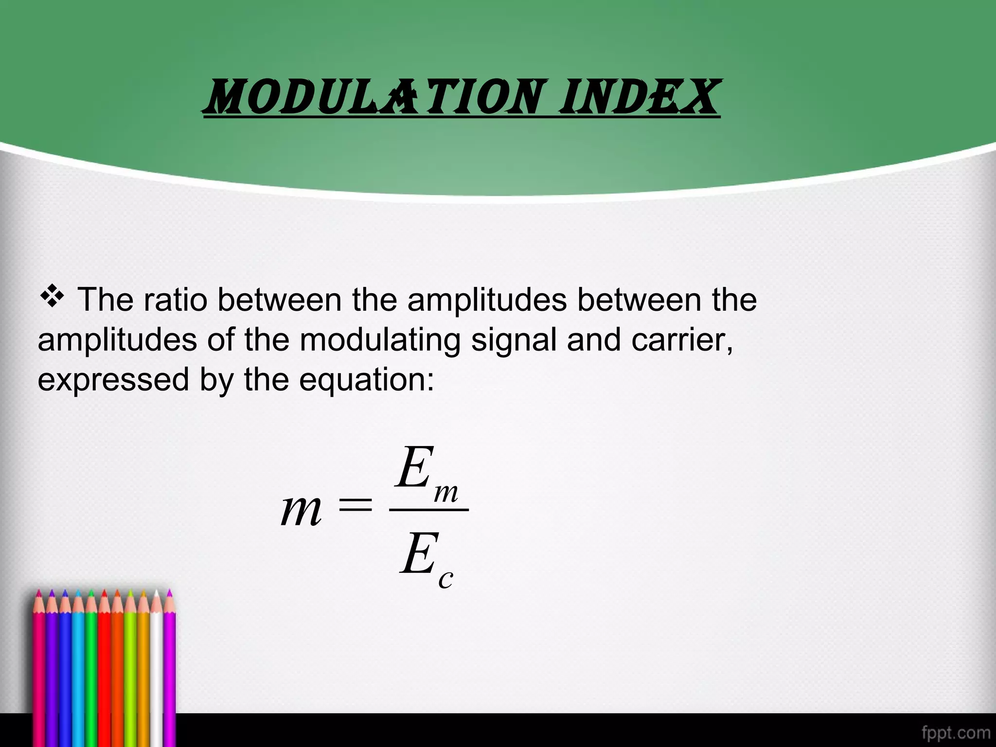
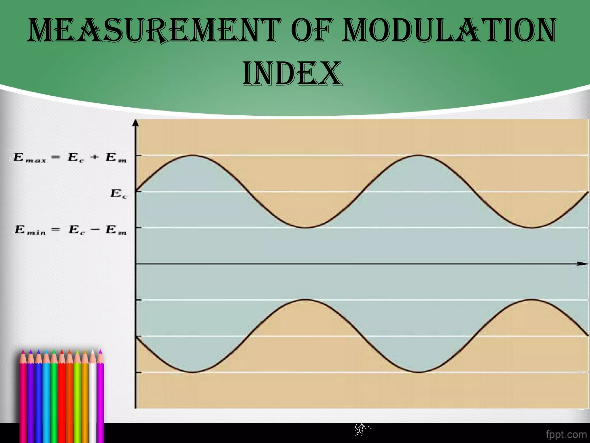
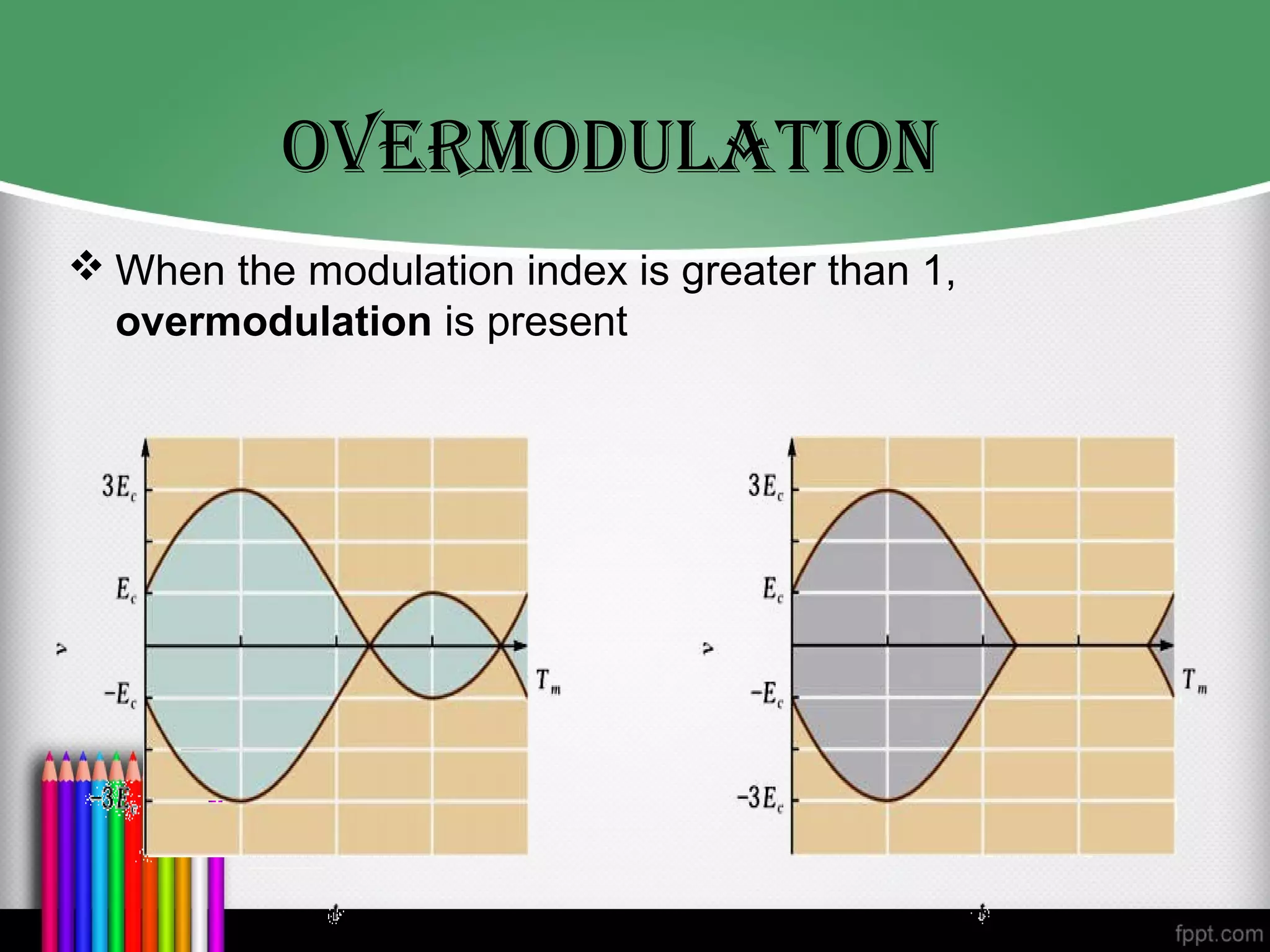


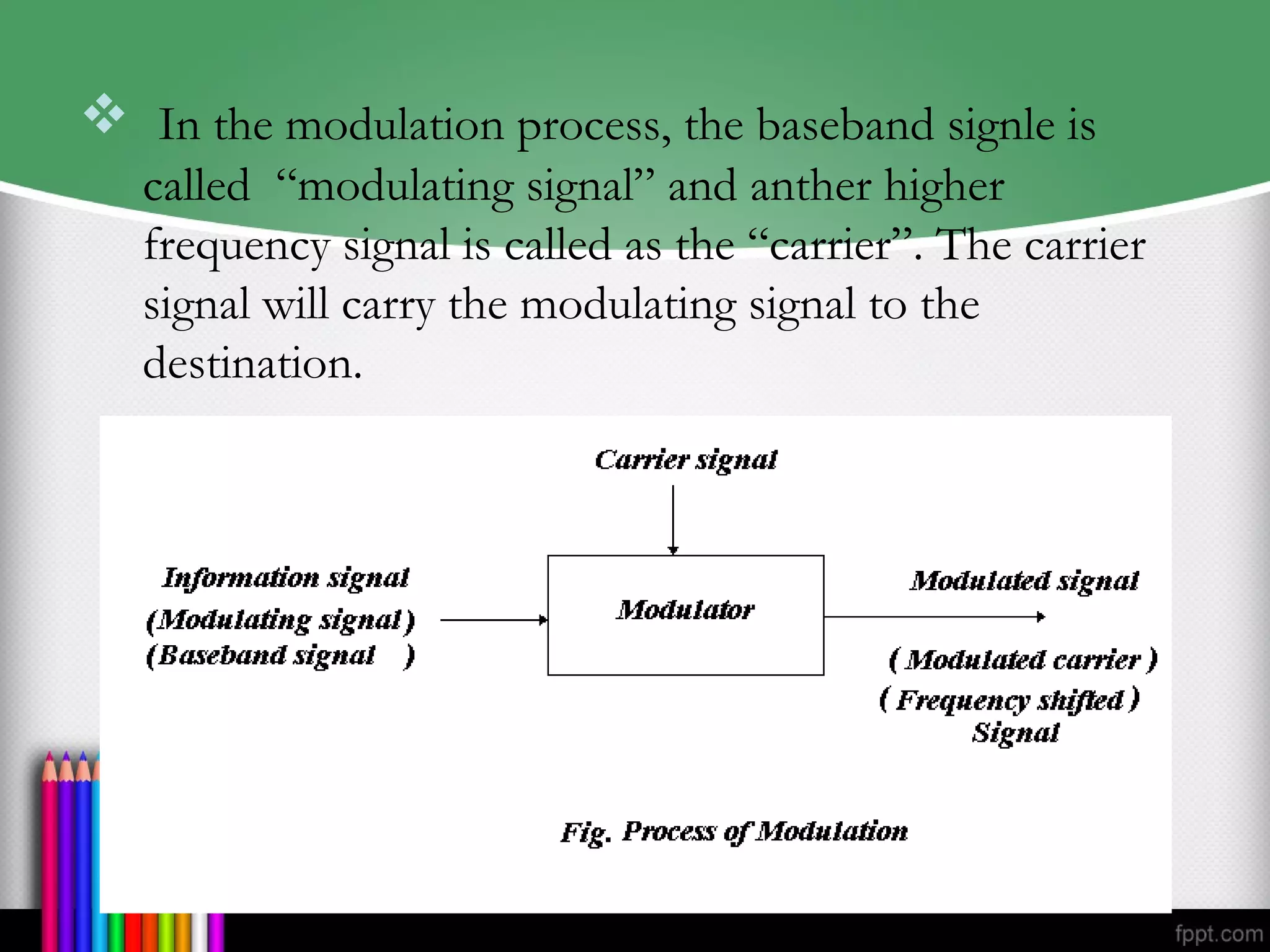
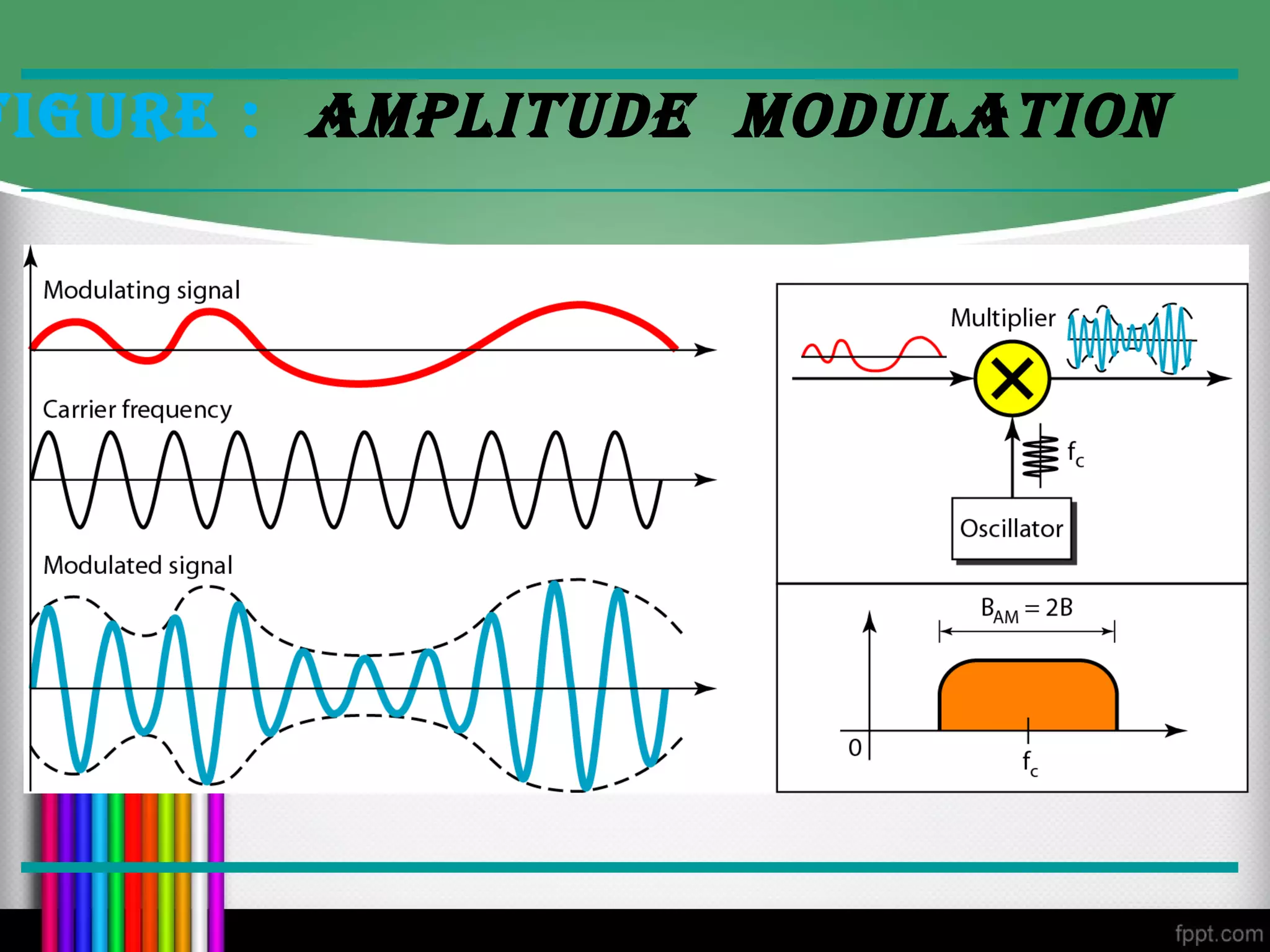
The document discusses modulation and amplitude modulation. It defines modulation as varying characteristics of a carrier signal in accordance with a modulation wave. Amplitude modulation varies the amplitude of a carrier signal proportionally to the instantaneous value of a modulating signal. The amplitude modulated signal is made up of the carrier signal, modulating signal, and sidebands containing the information. The modulation index indicates the ratio between the modulating signal and carrier amplitudes. Amplitude modulation has applications in broadcasting and communications.