Downloaded 174 times
![5
Amplitude Modulation
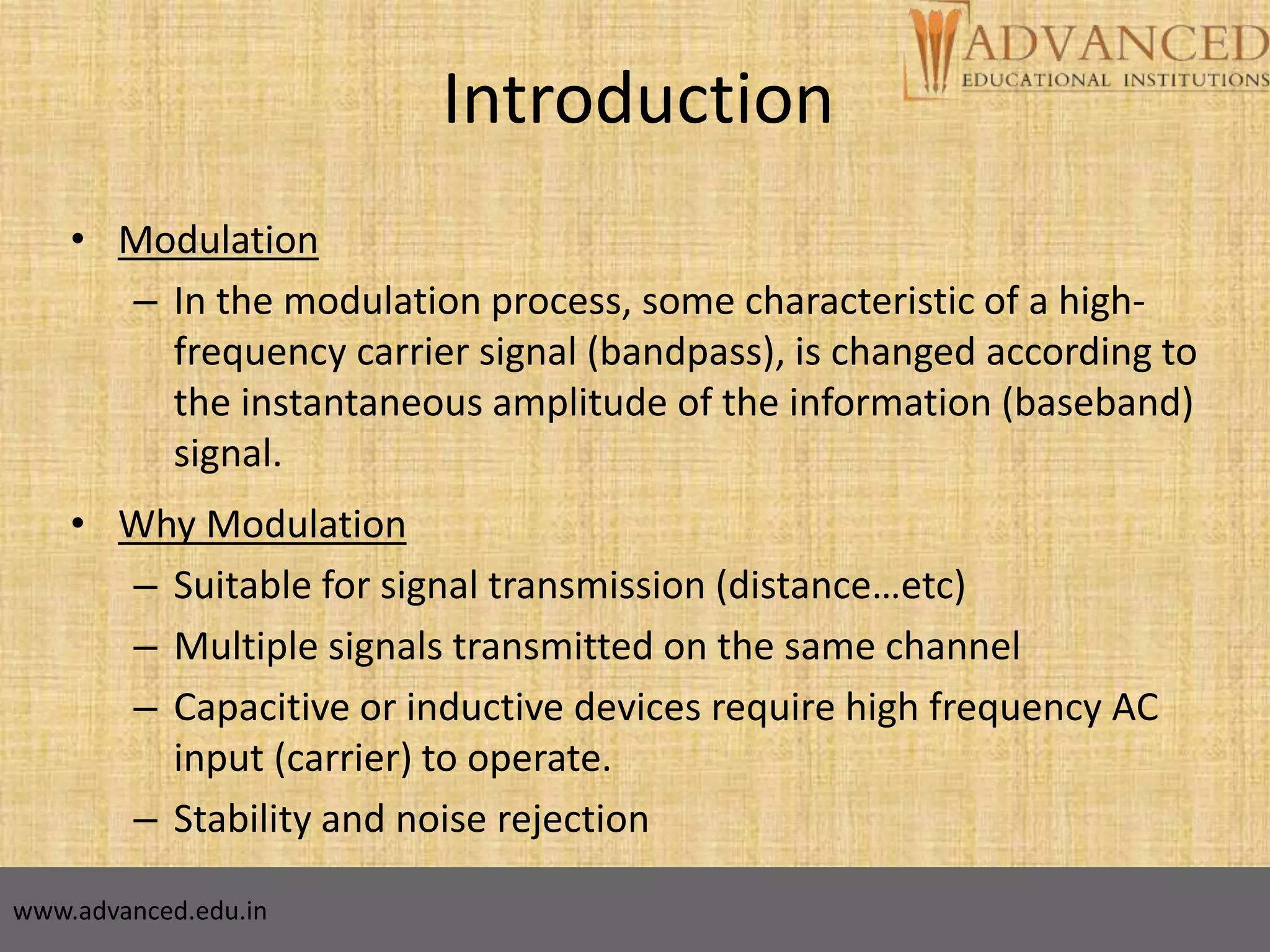
• The amplitude of high-carrier signal is varied
according to the instantaneous amplitude of the
modulating message signal m(t).
Carrier Signal: or
Modulating Message Signal: or
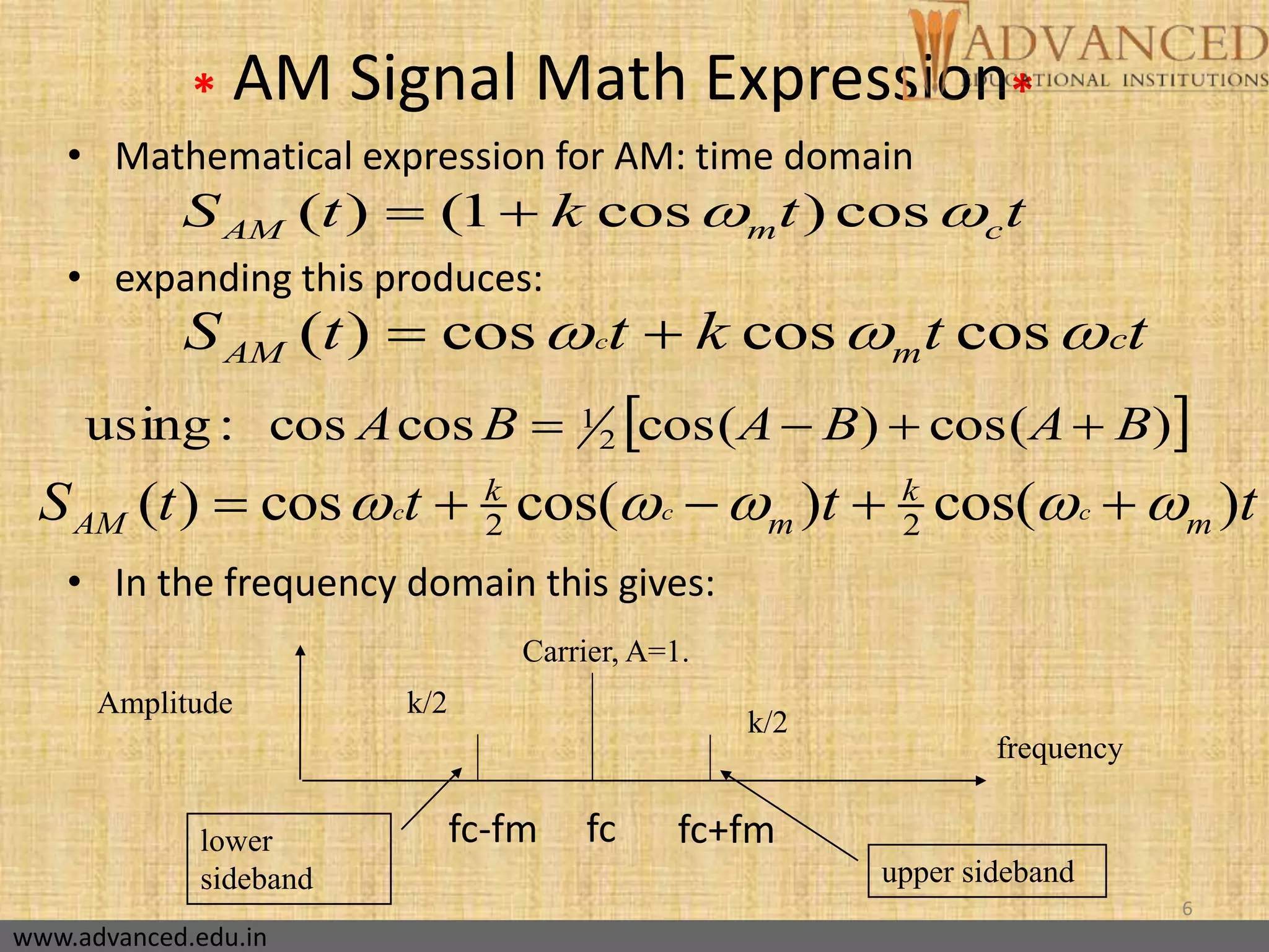
The AM Signal:
cos(2 ) cos( )
( ): cos(2 ) cos( )
( ) [ ( )]cos(2 )
c c
m m
AM c c
f t t
m t f t t
s t A m t f t
www.advanced.edu.in](https://image.slidesharecdn.com/amplitude-modulationsanjay-160217082414/75/Amplitude-modulation-sanjay-5-2048.jpg)
![10
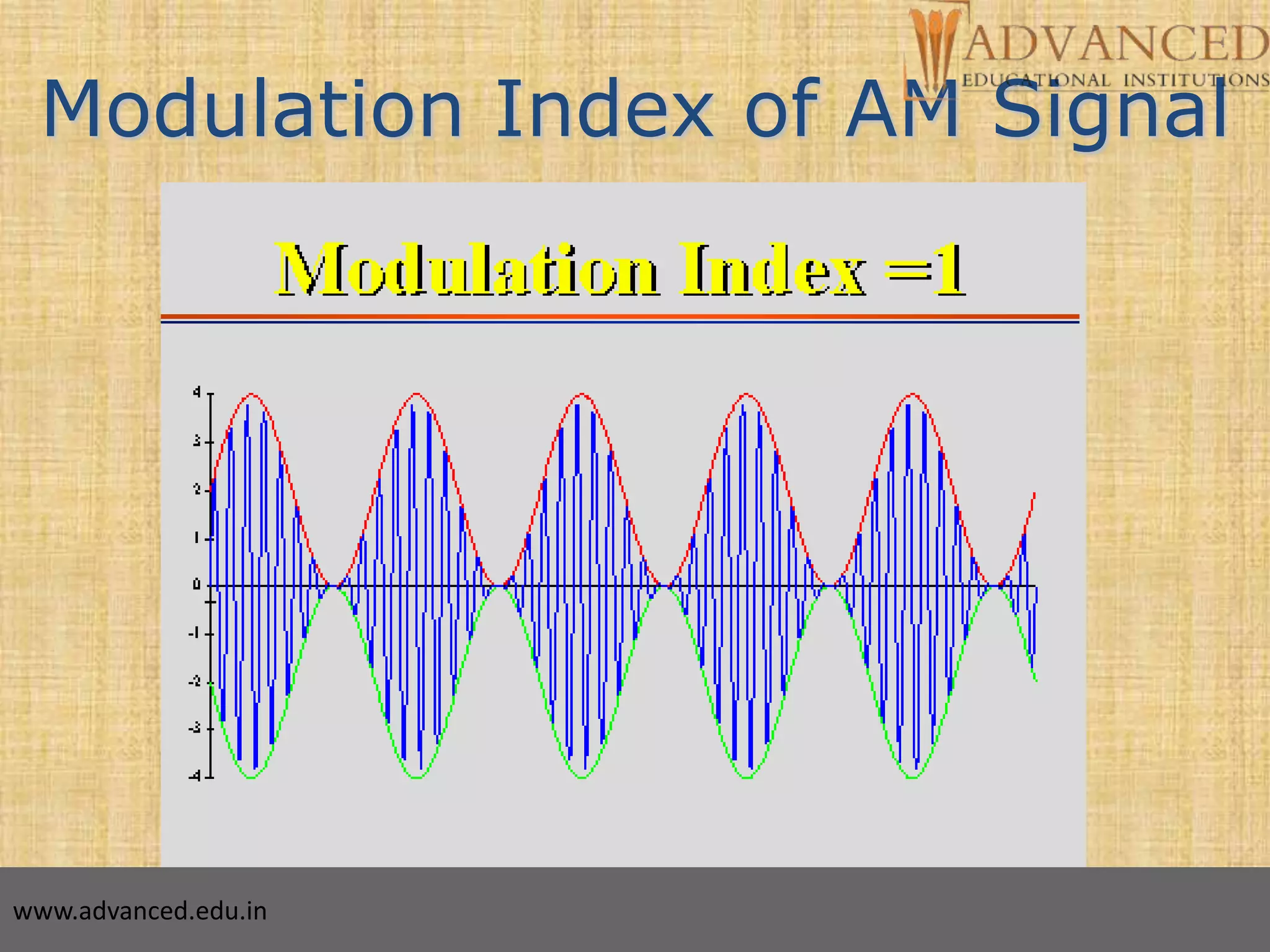
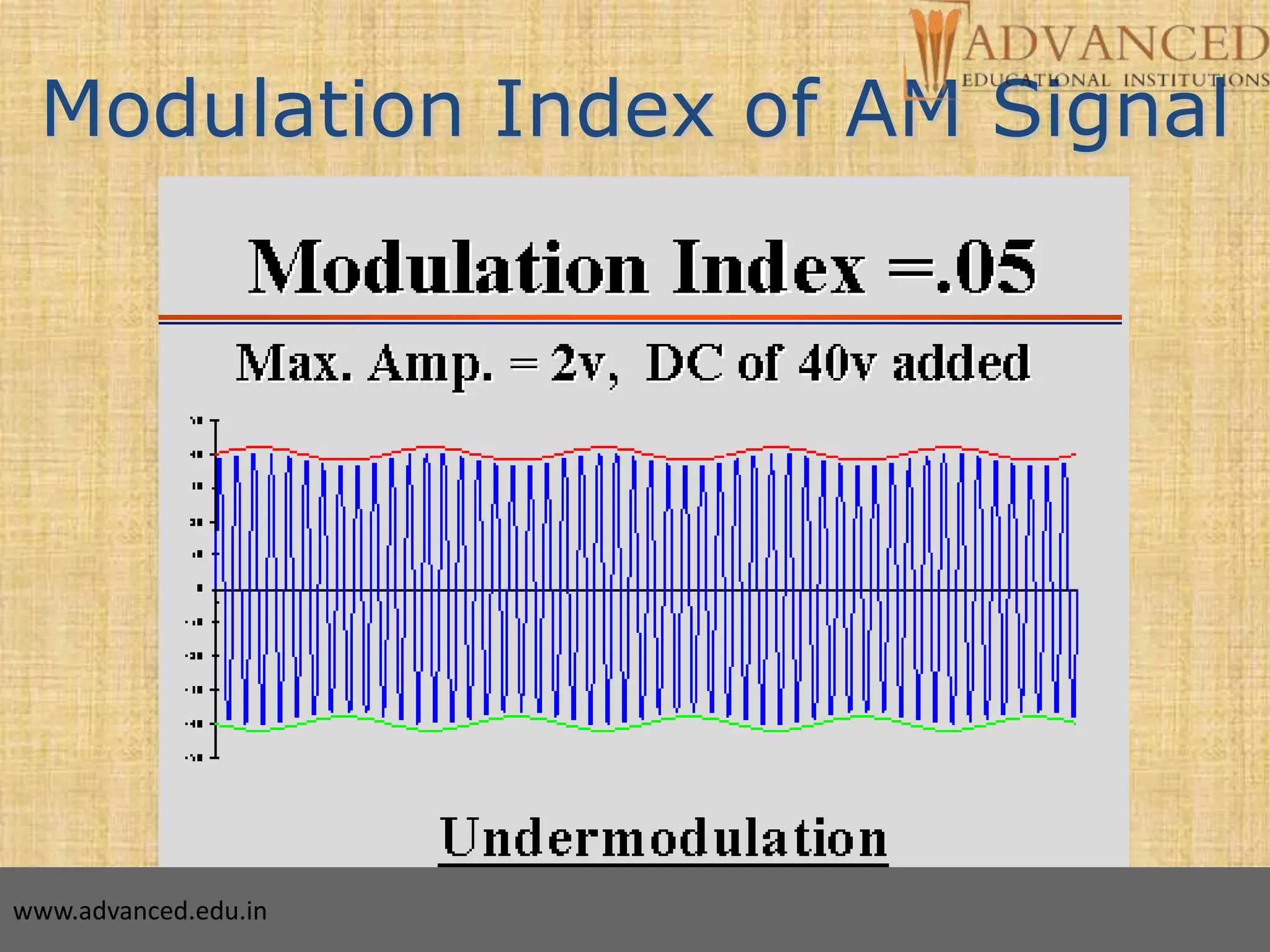
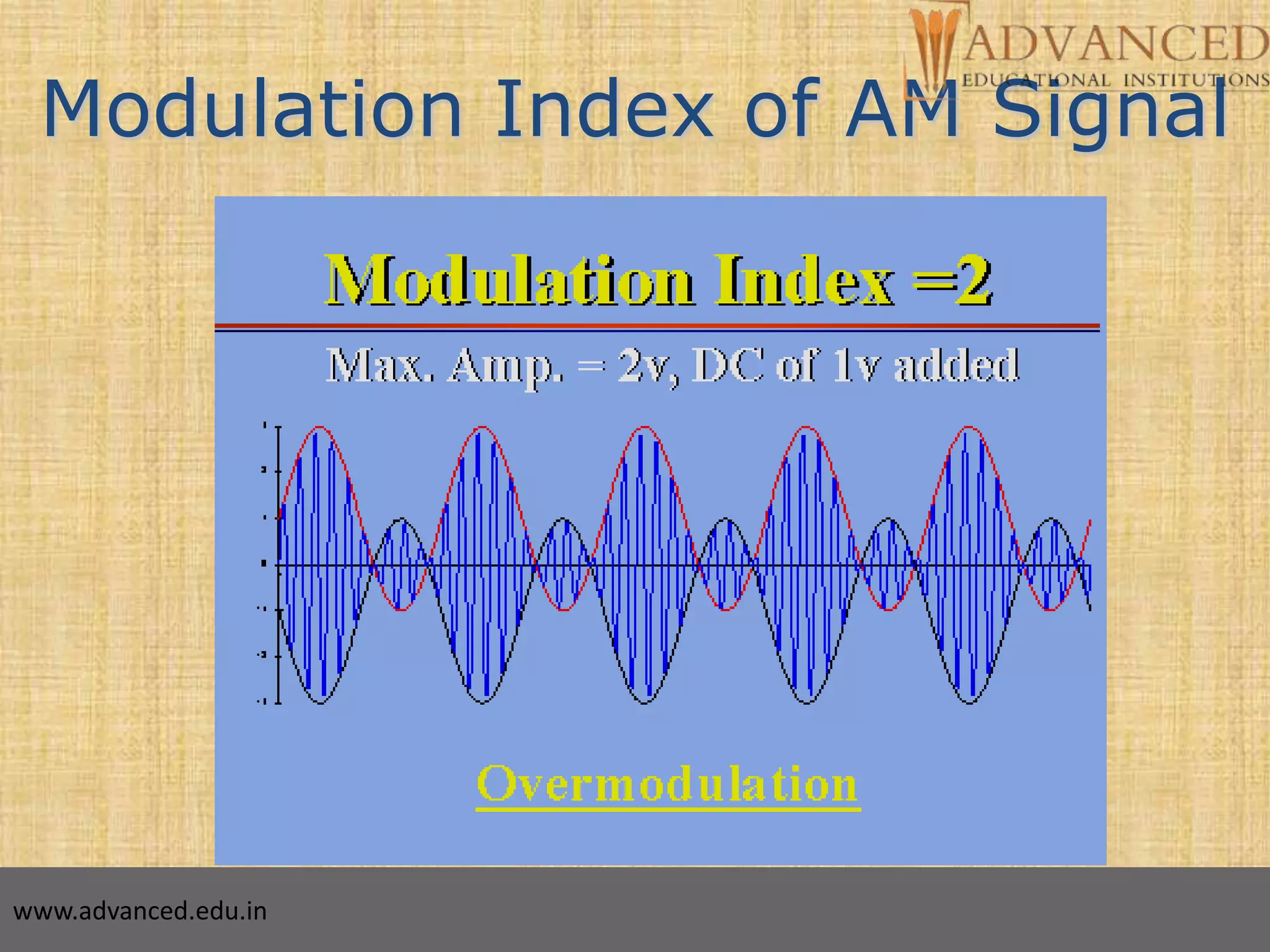
Modulation Index of AM Signal
m
c
A
k
A
)2cos()( tfAtm mm
Carrier Signal: cos(2 ) DC:c Cf t A
For a sinusoidal message signal
Modulation Index is defined as:
Modulated Signal: ( ) [ cos(2 )]cos(2 )
[1 cos(2 )]cos(2 )
AM c m m c
c m c
S t A A f t f t
A k f t f t
Modulation index k is a measure of the extent to
which a carrier voltage is varied by the modulating
signal. When k=0 no modulation, when k=1 100%
modulation, when k>1 over modulation.
www.advanced.edu.in](https://image.slidesharecdn.com/amplitude-modulationsanjay-160217082414/75/Amplitude-modulation-sanjay-10-2048.jpg)


This document provides an overview of amplitude modulation (AM), outlining its purpose, types, and mathematical expressions. It covers the modulation and demodulation processes, the importance of modulation index, and methods for detecting AM signals. Examples and applications of AM in broadcasting and mobile communications are illustrated, emphasizing the significance of maximizing modulation without causing distortion.