Download as PDF, PPTX
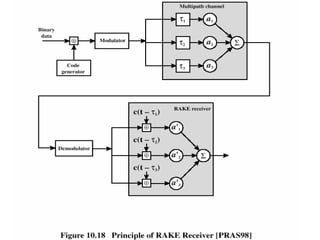
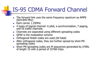
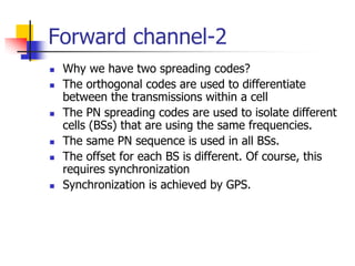
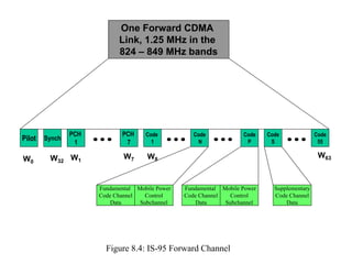

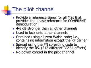
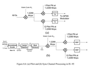
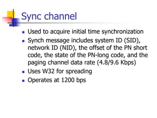


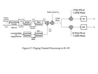
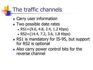
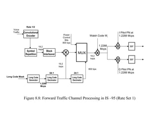
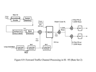
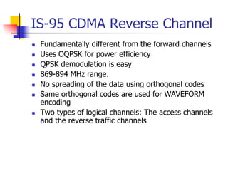
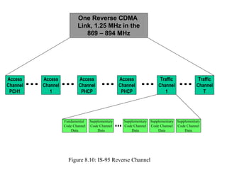
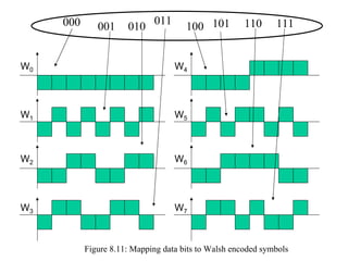


CDMA Technology & IS-95 - CDMA uses spread spectrum techniques where signals are spread over a wide frequency band before transmission. IS-95 is a 2G mobile telecommunications standard that uses CDMA. - IS-95 defines forward and reverse air interfaces with different channel structures using techniques like orthogonal codes, power control, and RAKE receivers. - The document discusses the technical details of the IS-95 forward and reverse channel structures including the pilot, sync, paging and traffic channels.


