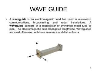
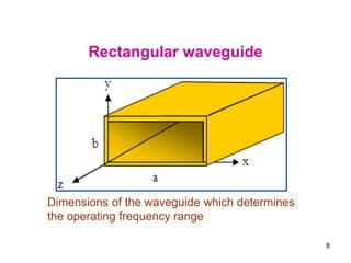
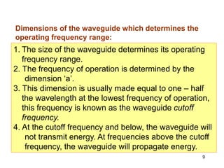
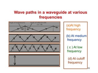
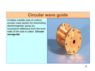
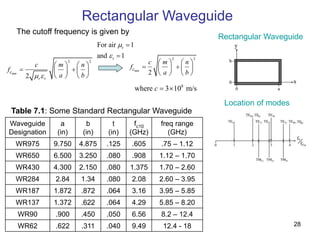
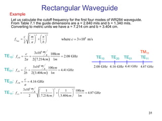
A waveguide is a structure that guides electromagnetic waves along its length. Rectangular waveguides consist of a hollow metal tube with a rectangular cross-section. Circular waveguides use a cylindrical cross-section. Waveguides can support transverse electric (TE) and transverse magnetic (TM) modes of propagation above a cutoff frequency that depends on the waveguide dimensions. Common applications include microwave communications, radar installations, and feeding antenna horns and dishes.
FellowBuddy.com is an innovative platform that brings students together to share notes, exam papers, study guides, project reports and presentation for upcoming exams.
We connect Students who have an understanding of course material with Students who need help.
Benefits:-
# Students can catch up on notes they missed because of an absence.
# Underachievers can find peer developed notes that break down lecture and study material in a way that they can understand
# Students can earn better grades, save time and study effectively
Our Vision & Mission – Simplifying Students Life
Our Belief – “The great breakthrough in your life comes when you realize it, that you can learn anything you need to learn; to accomplish any goal that you have set for yourself. This means there are no limits on what you can be, have or do.”
Like Us - https://www.facebook.com/FellowBuddycom
Dipole Antenna / Aerial Tutorial the dipole antenna or dipole aerial is a key element in the antenna environment. It can be used on its own or as part of another antenna system.
This narrated power point presentation attempts to explain the various dispersion mechanisms that are observed in optical fibers. Some fundamental terms and concepts are also discussed. The material will be useful for KTU final year B Tech students who prepare for the subject EC 405, Optical Communications.
By completing this presentation will be have a clear idea about Antenna's working principles, Antenna's Types & Antenna's Parameters. At the end to this document you'll have a brief idea about Antenna's Tilt vs Distance Calculation & Cluster wise optimum Antenna Selection procedure. Impact of antenna PIM & VSWR have been described elaborately in this document as well.
COMSATS Institute of Information and Technology, Sahiwal
Department of Electrical Engineering
Prepared By: Umaiz Ahmad and Yasir Zulfiqar
CONTACT:
+92-321-7899091
+92-336-0006247
There is a mainly two types of waveguide which are mainly used in microwave transmission. A Rectangular waveguide and a circular waveguide. Microwave Propagation is being through these waveguides via different modes at different frequencies. But in practical implementation many problems arise like an ascetic excitation method, efficiency of particular mode, complex calculation etc., and an alternation is used. It is called a waveguide converter. In this paper different types of methods are analyzed and describe an output of these methods.
Spectra-Physics is a brand within the MKS Instruments Light & Motion division. The Spectra-Physics product portfolio consists of a broad spectrum of lasers for precision industrial and scientific research applications. Spectra-Physics products combine groundbreaking laser technologies with deep applications expertise to deliver disruptive performance and lower total cost of ownership. From the manufacturing floor and semiconductor fab to the research laboratory, Spectra-Physics lasers enhance our customers’ capabilities and productivity in the semiconductor, industrial technologies, life and health sciences, and research markets.
Microstrip Antenna for ISM Band (2.4GHz) Applications-A reviewIJERA Editor
The past decade has seen a rapid development of wireless communication systems. This continuous trend is bringing about a wave of new wireless devices placing several demands on the antenna such as size miniaturization, power consumption, simplicity, compatibility with printed-circuit technology, low profile, light weight, lower return loss and good radiation properties. This paper provides a comprehensive review of the research work done in the recent past by various authors on the design and optimization of the planar microstrip antenna operating in ISM band. An exhaustive list of reference has been provided.
Student information management system project report ii.pdfKamal Acharya
Our project explains about the student management. This project mainly explains the various actions related to student details. This project shows some ease in adding, editing and deleting the student details. It also provides a less time consuming process for viewing, adding, editing and deleting the marks of the students.
Welcome to WIPAC Monthly the magazine brought to you by the LinkedIn Group Water Industry Process Automation & Control.
In this month's edition, along with this month's industry news to celebrate the 13 years since the group was created we have articles including
A case study of the used of Advanced Process Control at the Wastewater Treatment works at Lleida in Spain
A look back on an article on smart wastewater networks in order to see how the industry has measured up in the interim around the adoption of Digital Transformation in the Water Industry.
Explore the innovative world of trenchless pipe repair with our comprehensive guide, "The Benefits and Techniques of Trenchless Pipe Repair." This document delves into the modern methods of repairing underground pipes without the need for extensive excavation, highlighting the numerous advantages and the latest techniques used in the industry.
Learn about the cost savings, reduced environmental impact, and minimal disruption associated with trenchless technology. Discover detailed explanations of popular techniques such as pipe bursting, cured-in-place pipe (CIPP) lining, and directional drilling. Understand how these methods can be applied to various types of infrastructure, from residential plumbing to large-scale municipal systems.
Ideal for homeowners, contractors, engineers, and anyone interested in modern plumbing solutions, this guide provides valuable insights into why trenchless pipe repair is becoming the preferred choice for pipe rehabilitation. Stay informed about the latest advancements and best practices in the field.
Final project report on grocery store management system..pdfKamal Acharya
In today’s fast-changing business environment, it’s extremely important to be able to respond to client needs in the most effective and timely manner. If your customers wish to see your business online and have instant access to your products or services.
Online Grocery Store is an e-commerce website, which retails various grocery products. This project allows viewing various products available enables registered users to purchase desired products instantly using Paytm, UPI payment processor (Instant Pay) and also can place order by using Cash on Delivery (Pay Later) option. This project provides an easy access to Administrators and Managers to view orders placed using Pay Later and Instant Pay options.
In order to develop an e-commerce website, a number of Technologies must be studied and understood. These include multi-tiered architecture, server and client-side scripting techniques, implementation technologies, programming language (such as PHP, HTML, CSS, JavaScript) and MySQL relational databases. This is a project with the objective to develop a basic website where a consumer is provided with a shopping cart website and also to know about the technologies used to develop such a website.
This document will discuss each of the underlying technologies to create and implement an e- commerce website.
About
Indigenized remote control interface card suitable for MAFI system CCR equipment. Compatible for IDM8000 CCR. Backplane mounted serial and TCP/Ethernet communication module for CCR remote access. IDM 8000 CCR remote control on serial and TCP protocol.
• Remote control: Parallel or serial interface.
• Compatible with MAFI CCR system.
• Compatible with IDM8000 CCR.
• Compatible with Backplane mount serial communication.
• Compatible with commercial and Defence aviation CCR system.
• Remote control system for accessing CCR and allied system over serial or TCP.
• Indigenized local Support/presence in India.
• Easy in configuration using DIP switches.
Technical Specifications
Indigenized remote control interface card suitable for MAFI system CCR equipment. Compatible for IDM8000 CCR. Backplane mounted serial and TCP/Ethernet communication module for CCR remote access. IDM 8000 CCR remote control on serial and TCP protocol.
Key Features
Indigenized remote control interface card suitable for MAFI system CCR equipment. Compatible for IDM8000 CCR. Backplane mounted serial and TCP/Ethernet communication module for CCR remote access. IDM 8000 CCR remote control on serial and TCP protocol.
• Remote control: Parallel or serial interface
• Compatible with MAFI CCR system
• Copatiable with IDM8000 CCR
• Compatible with Backplane mount serial communication.
• Compatible with commercial and Defence aviation CCR system.
• Remote control system for accessing CCR and allied system over serial or TCP.
• Indigenized local Support/presence in India.
Application
• Remote control: Parallel or serial interface.
• Compatible with MAFI CCR system.
• Compatible with IDM8000 CCR.
• Compatible with Backplane mount serial communication.
• Compatible with commercial and Defence aviation CCR system.
• Remote control system for accessing CCR and allied system over serial or TCP.
• Indigenized local Support/presence in India.
• Easy in configuration using DIP switches.
Hybrid optimization of pumped hydro system and solar- Engr. Abdul-Azeez.pdffxintegritypublishin
Advancements in technology unveil a myriad of electrical and electronic breakthroughs geared towards efficiently harnessing limited resources to meet human energy demands. The optimization of hybrid solar PV panels and pumped hydro energy supply systems plays a pivotal role in utilizing natural resources effectively. This initiative not only benefits humanity but also fosters environmental sustainability. The study investigated the design optimization of these hybrid systems, focusing on understanding solar radiation patterns, identifying geographical influences on solar radiation, formulating a mathematical model for system optimization, and determining the optimal configuration of PV panels and pumped hydro storage. Through a comparative analysis approach and eight weeks of data collection, the study addressed key research questions related to solar radiation patterns and optimal system design. The findings highlighted regions with heightened solar radiation levels, showcasing substantial potential for power generation and emphasizing the system's efficiency. Optimizing system design significantly boosted power generation, promoted renewable energy utilization, and enhanced energy storage capacity. The study underscored the benefits of optimizing hybrid solar PV panels and pumped hydro energy supply systems for sustainable energy usage. Optimizing the design of solar PV panels and pumped hydro energy supply systems as examined across diverse climatic conditions in a developing country, not only enhances power generation but also improves the integration of renewable energy sources and boosts energy storage capacities, particularly beneficial for less economically prosperous regions. Additionally, the study provides valuable insights for advancing energy research in economically viable areas. Recommendations included conducting site-specific assessments, utilizing advanced modeling tools, implementing regular maintenance protocols, and enhancing communication among system components.
1. WAVE GUIDE
• A waveguide is an electromagnetic feed line used in microwave
communications, broadcasting, and radar installations. A
waveguide consists of a rectangular or cylindrical metal tube or
pipe. The electromagnetic field propagates lengthwise. Waveguides
are most often used with horn antenna s and dish antenna.
1
2. Introduction
At frequencies higher than 3 GHz, transmission of electromagnetic
energy along the transmission lines and cables becomes difficult.
This is due to the losses that occur both in the solid dielectric needed
to support the conductor and in the conductors themselves.
A metallic tube can be used to transmit electromagnetic wave at the
above frequencies
2
4. 4
Possible Types of modes
1. Transverse Electro Magnetic (TEM) wave:
Here both electric and magnetic fields are directed
components. (i.e.) E z = 0 and Hz = 0
2. Transverse Electric (TE) wave: Here only the electric field is purely
transverse to the direction of propagation and the magnetic field is not purely
transverse. (i.e.) E z = 0, Hz ≠ 0
5. 5
4. Hybrid (HE) wave: Here neither electric nor
magnetic fields are purely transverse to the direction of propagation.
(i.e.) E z ≠ 0, Hz ≠ 0.
3. Transverse Magnetic (TM) wave: Here only magnetic field is transverse
to the direction of propagation and the electric field is not purely
transverse. (i.e.) E z ≠ 0, Hz = 0.
Possible Types of modes
7. 7
Rectangular Waveguides
Any shape of cross section of a waveguide
can support electromagnetic waves of
which rectangular and circular waveguides
have become more common.
A waveguide having rectangular cross
section is known as Rectangular
waveguide
9. 9
1. The size of the waveguide determines its operating
frequency range.
2. The frequency of operation is determined by the
dimension ‘a’.
3. This dimension is usually made equal to one – half
the wavelength at the lowest frequency of operation,
this frequency is known as the waveguide cutoff
frequency.
4. At the cutoff frequency and below, the waveguide will
not transmit energy. At frequencies above the cutoff
frequency, the waveguide will propagate energy.
Dimensions of the waveguide which determines the
operating frequency range:
10. 10
Wave paths in a waveguide at various
frequencies
Angle of incidence(A) Angle of reflection (B)
(A = B)
(a)At high
frequency
(b) At medium
frequency
( c ) At low
frequency
(d) At cutoff
frequency
11. 11
Wave propagation
When a probe launches energy into the
waveguide, the electromagnetic fields bounce
off the side walls of the waveguide as shown in
the above diagram.
The angles of incidence and reflection depend
upon the operating frequency. At high
frequencies, the angles are large and therefore,
the path between the opposite walls is relatively
long as shown in Fig.
12. 12
At lower frequency, the angles decrease and the path between the sides
shortens.
When the operating frequency is reaches the cutoff frequency of the
waveguide, the signal simply bounces back and forth directly between the side
walls of the waveguide and has no forward motion.
At cut off frequency and below, no energy will propagate.
13. 13
Cut off frequency
The exact size of the wave guide is selected
based on the desired operating frequency.
The size of the waveguide is chosen so that
its rectangular width is greater than one –
half the wavelength but less than the one
wavelength at the operating frequency.
This gives a cutoff frequency that is below
the operating frequency, thereby ensuring
that the signal will be propagated down the
line.
14. 14
Representation of modes
The general symbol of representation will be TE m, n
or TM m, n where the subscript m indicates the
number of half wave variations of the electric field
intensity along the b ( wide) dimension of the
waveguide.
The second subscript n indicates the number of half
wave variations of the electric field in the a (narrow)
dimension of the guide.
The TE 1, 0 mode has the longest operating
wavelength and is designated as the dominant
mode. It is the mode for the lowest frequency that
can be propagated in a waveguide.
15. 15
Expression for cut off wavelength
For a standard rectangular waveguide, the cutoff
wavelength is given by,
2
2
2
b
n
a
m
c
Where a and b are measured in centimeters
16. 16
A Hollow metallic tube of uniform
circular cross section for transmitting
electromagnetic waves by
successive reflections from the inner
walls of the tube is called Circular
waveguide.
Circular wave guide
17. 17
Circular wave guide
The circular waveguide is used in many special
applications in microwave techniques.
It has the advantage of greater power – handling
capacity and lower attenuation for a given cutoff
wavelength. However, the disadvantage of
somewhat greater size and weight.
The polarization of the transmitted wave can be
altered due to the minor irregularities of the wall
surface of the circular guide, whereas the
rectangular wave guide the polarization is fixed
19. 19
Description
The wave of lowest frequency or the dominant
mode in the circular waveguide is the TE11 mode.
The first subscript m indicates the number of full –
wave variations of the radial component of the
electric field around the circumference of the
waveguide.
The second subscript n indicates the number of
half – wave variations across the diameter.
The field configurations of TE11 mode in the
circular waveguide is shown in the diagram below
20. 20
Cut off wavelength
The cutoff wavelength for dominant mode of
propagation TE11 in circular waveguide of radius
‘a’ is given by
1.814
π
2 a
c
The cutoff wavelength for dominant mode of
propagation TM01 in circular waveguide of radius ‘a’
is given by
2.405
π
2 a
c
21. 21
Applications of circular waveguide
Rotating joints in radars to connect the horn
antenna feeding a parabolic reflector (which
must rotate for tracking)
TE01 mode suitable for long distance waveguide
transmission above 10 GHz.
Short and medium distance broad band
communication (could replace / share coaxial
and microwave links)
22. 22
Worked Example 2.4
The dimensions of the waveguide are 2.5 cm 1 cm.
The frequency is 8.6 GHz. Find (i) possible modes
and (ii) cut – off frequency for TE waves.
Solution:
Given a = 2.5 cm , b = 1 cm and f = 8.6 GHz
Free space wavelength
cm
488
.
3
10
8
10
3
9
10
0
f
C
23. 23
Solution
The condition for the wave to propagate is
that λC > λ0
For TE01 mode
cm
2
1
2
2
2
2
2
2
2
2
2
b
a
ab
a
n
b
m
ab
C
Since λC < λ0, TE01 does not propagate
24. 24
For TE10 mode, λC = 2a = 2 2.5 = 5 cm
Since λC > λ0 , TE10 mode is a possible mode.
Cut – off frequency = GHz
6
5
10
3 10
C
C
C
f
Cut-off wavelength
for TE11 mode
cm
856
.
1
)
1
(
)
5
.
2
(
1
5
.
2
2
2
2
2
2
2
b
a
ab
For TE11 λC < λ0 , TE11 is not possible.
The possible mode is TE10 mode.
The cut – off frequency = 6 GHz
=
25. 25
Worked Example 2.5
For the dominant mode propagated in an air filled
circular waveguide, the cut – off wavelength is 10 cm.
Find (i) the required size or cross sectional area of the
guide and (ii) the frequencies that can be used for this
mode of propagation
The cut – off wavelength = λC = 10 cm
The radius of the circular waveguide ,
cm
3
9
.
2
2
841
.
1
10
=
r
26. Waveguides
• In the previous chapters, a pair of
conductors was used to guide
electromagnetic wave propagation.
This propagation was via the
transverse electromagnetic (TEM)
mode, meaning both the electric and
magnetic field components were
transverse, or perpendicular, to the
direction of propagation.
• In this chapter we investigate wave-
guiding structures that support
propagation in non-TEM modes,
namely in the transverse electric (TE)
and transverse magnetic (TM) modes.
• In general, the term waveguide refers
to constructs that only support non-
TEM mode propagation. Such
constructs share an important trait:
they are unable to support wave
propagation below a certain frequency,
termed the cutoff frequency.
Rectangular
waveguide
Circular
waveguide
Optical Fiber
Dielectric Waveguide
26
27. Rectangular Waveguide
Location of modes
• Let us consider a rectangular waveguide
with interior dimensions are a x b,
• Waveguide can support TE and TM modes.
– In TE modes, the electric field is transverse
to the direction of propagation.
– In TM modes, the magnetic field that is
transverse and an electric field component is
in the propagation direction.
• The order of the mode refers to the field
configuration in the guide, and is given by m
and n integer subscripts, TEmn and TMmn.
– The m subscript corresponds to the number
of half-wave variations of the field in the x
direction, and
– The n subscript is the number of half-wave
variations in the y direction.
• A particular mode is only supported above
its cutoff frequency. The cutoff frequency is
given by
2 2 2 2
1
2 2
mn
r r
c
m n c m n
f
a b a b
Rectangular Waveguide
1 1 1 1
o r o r o o r r r r
c
u
8
where 3 10 m/s
c 27
28. Table 7.1: Some Standard Rectangular Waveguide
Waveguide
Designation
a
(in)
b
(in)
t
(in)
fc10
(GHz)
freq range
(GHz)
WR975 9.750 4.875 .125 .605 .75 – 1.12
WR650 6.500 3.250 .080 .908 1.12 – 1.70
WR430 4.300 2.150 .080 1.375 1.70 – 2.60
WR284 2.84 1.34 .080 2.08 2.60 – 3.95
WR187 1.872 .872 .064 3.16 3.95 – 5.85
WR137 1.372 .622 .064 4.29 5.85 – 8.20
WR90 .900 .450 .050 6.56 8.2 – 12.4
WR62 .622 .311 .040 9.49 12.4 - 18
Location of modes
Rectangular Waveguide
The cutoff frequency is given by
2 2
2
mn
r r
c
c m n
f
a b
2 2
2
mn
c
c m n
f
a b
8
where 3 10 m/s
c
r
r
For air 1
and 1
28
29. To understand the concept of cutoff frequency, you can use the analogy of a road
system with lanes having different speed limits.
29
30. Rectangular Waveguide
Rectangular Waveguide
• Let us take a look at the field pattern for two
modes, TE10 and TE20
– In both cases, E only varies in the x direction;
since n = 0, it is constant in the y direction.
– For TE10, the electric field has a half sine
wave pattern, while for TE20 a full sine wave
pattern is observed.
30
31. Rectangular Waveguide
Example
Let us calculate the cutoff frequency for the first four modes of WR284 waveguide.
From Table 7.1 the guide dimensions are a = 2.840 mils and b = 1.340 mils.
Converting to metric units we have a = 7.214 cm and b = 3.404 cm.
2 2
2
mn
c
c m n
f
a b
8
10
3 10 100
2.08 GHz
2 2 7.214 1
c
m
x
c cm
s
f
a cm m
8
01
3 10 100
4.41 GHz
2 2 3.404 1
c
m
x
c cm
s
f
b cm m
20
4.16 GHz
c
c
f
a
8 2 2
11
3 10 1 1 100
4.87 GHz
2 7.214 3.404 1
c
m
x cm
s
f
cm cm m
TE10:
TE01:
8
where 3 10 m/s
c
TE20:
TE11:
TE10 TE01
TE20 TE11
2.08 GHz 4.16 GHz 4.41 GHz 4.87 GHz
TM11
31
33. Rectangular Waveguide - Wave Propagation
We can achieve a qualitative understanding of
wave propagation in waveguide by considering the
wave to be a superposition of a pair of TEM waves.
Let us consider a TEM wave propagating in the z
direction. Figure shows the wave fronts; bold lines
indicating constant phase at the maximum value of
the field (+Eo), and lighter lines indicating constant
phase at the minimum value (-Eo).
The waves propagate at a velocity uu, where the u
subscript indicates media unbounded by guide
walls. In air, uu = c.
33
34. Now consider a pair of identical TEM waves, labeled
as u+ and u- in Figure (a). The u+ wave is
propagating at an angle + to the z axis, while the u-
wave propagates at an angle –.
These waves are combined in Figure (b). Notice that
horizontal lines can be drawn on the superposed
waves that correspond to zero field. Along these
lines the u+ wave is always 180 out of phase with
the u- wave.
Rectangular Waveguide - Wave Propagation
34
35. Rectangular Waveguide - Wave Propagation
Since we know E = 0 on a perfect conductor, we can replace
the horizontal lines of zero field with perfect conducting walls.
Now, u+ and u- are reflected off the walls as they propagate
along the guide.
The distance separating adjacent zero-field lines in Figure (b),
or separating the conducting walls in Figure (a), is given as the
dimension a in Figure (b).
The distance a is determined by the angle and by the
distance between wavefront peaks, or the wavelength . For a
given wave velocity uu, the frequency is f = uu/.
If we fix the wall separation at a, and change the frequency, we
must then also change the angle if we are to maintain a
propagating wave. Figure (b) shows wave fronts for the u+
wave.
The edge of a +Eo wave front (point A) will line up with the
edge of a –Eo front (point B), and the two fronts must be /2
apart for the m = 1 mode.
(a)
(b)
a
35
36. Rectangular Waveguide - Wave Propagation
The waveguide can support propagation as long as the wavelength
is smaller than a critical value, c, that occurs at = 90, or
2 u
c
c
u
a
m f
Where fc is the cutoff frequency for the propagating mode.
sin c
c
f
f
We can relate the angle to the operating frequency and
the cutoff frequency by
2
sin
m
a
For any value of m, we can write by simple trigonometry
2
sin u
u
a
m f
36
37. Rectangular Waveguide - Wave Propagation
A constant phase point moves along the wall from A to D. Calling
this phase velocity up, and given the distance lAD is
2
cos
AD
m
l
Then the time tAD to travel from A to D is
2
cos
AD
p p
AD
l m
t
u u
Since the times tAD and tAC must be equal, we have
cos
u
p
u
u
The time tAC it takes for the wavefront to move from A
to C (a distance lAC) is
2
Wavefront Velocity
Distance from A to C
AC
u u
AC
l m
t
u u
37
38.
2
1
u
p
c
u
u
f
f
Rectangular Waveguide - Wave Propagation
2
2 2
cos cos 1 sin 1 c
f f
cos
u
p
u
u
The Phase velocity is given by
using
cos
G u
u u
2
1 c
G u
f
u u
f
The Group velocity is given by
The Wave velocity is given by
1 1 1 1
u
o r o r o o r r r r
c
u
8
where 3 10 m/s
c
Wave velocity
Phase velocity
p
u
Group velocity
Beach
Ocean
Phase velocity
p
u
u
u
Wave velocity
u
u
G
u Group velocity
Analogy!
Point of contact
38
39. Rectangular Waveguide - Wave Propagation
The ratio of the transverse electric field to the transverse magnetic field for a
propagating mode at a particular frequency is the waveguide impedance.
2
,
1
TE u
mn
c
Z
f
f
For a TE mode, the wave impedance is For a TM mode, the wave impedance is
2
.
1
TM c
mn u
f
Z
f
2
1 c
u
f
f
The phase constant is given by
2
1
u
c
f
f
The guide wavelength is given by
39
41. Example
Rectangular Waveguide
Let’s determine the TE mode impedance looking into a 20 cm long section of shorted WR90
waveguide operating at 10 GHz.
From the Waveguide Table 7.1, a = 0.9 inch (or) 2.286 cm and b = 0.450 inch (or) 1.143 cm.
2 2
2
mn
c
c m n
f
a b
TE10 6.56 GHz
Mode Cutoff Frequency
TE01 13.12 GHz
TE11 14.67 GHz
TE20 13.13 GHz
TE02 26.25 GHz
At 10 GHz, only the TE10 mode is supported!
TE10 6.56 GHz
Mode Cutoff Frequency
TE01 13.12 GHz
TE11 14.67 GHz
TE20 13.13 GHz
TE02 26.25 GHz
TE10 TE20
TE01 TE11
TM11
6.56 GHz 13.12 GHz
TE02
26.25 GHz
14.67 GHz
Rearrange
13.13 GHz
41
42. Example
Rectangular Waveguide
10
2
120
500 .
6.56GHz
1-
10GHz
TE
Z
10 tan
IN
TE
Z jZ
l
The impedance looking into a short circuit is
given by
The TE10 mode impedance
2 2
9 2
8
2
1 1
2 10 10 6.56
1 158
10
3 10
c c
u
f f
f
f c f
x Hz GHz rad
m GHz m
x
s
The TE10 mode propagation constant is
given by
500 tan 31.6 100
IN
Z j j
500 tan 158 0.2
IN
rad
Z j m
m
42