Downloaded 407 times


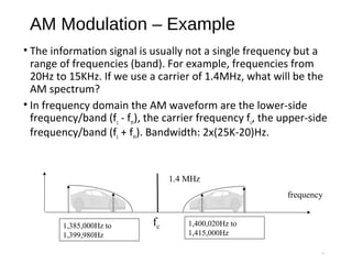
![Amplitude Modulation
•The amplitude of high-carrier signal is varied according
to the instantaneous amplitude of the modulating
message signal m(t).
Carrier Signal: or
Modulating Message Signal: or
The AM Signal:
cos(2 ) cos( )
( ) : cos(2 ) cos( )
( ) [ ( )]cos(2 )
c c
m m
AM c c
f t t
m t f t t
s t A m t f t
π ω
π ω
π= +
6](https://image.slidesharecdn.com/amplitudemodulation2-170220092501/85/Amplitude-modulation-6-320.jpg)
![* AM Signal Math Expression*
• Mathematical expression for AM: time domain
• expanding this produces:
• In the frequency domain this gives:
7
( ) (1 cos ) cosAM m cS t k t tω ω= +
( ) cos cos cosc cAM mS t t k t tω ω ω= +
[ ])cos()cos(coscos:using 2
1 BABABA ++−=
2 2( ) cos cos( ) cos( )c c c
k k
AM m mS t t t tω ω ω ω ω= + − + +
frequency
k/2
k/2
Carrier, A=1.
upper sideband
lower
sideband
Amplitude
fcfc-fm fc+fm](https://image.slidesharecdn.com/amplitudemodulation2-170220092501/85/Amplitude-modulation-7-320.jpg)


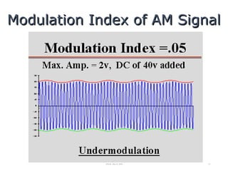
![Modulation Index of AM Signal
m
c
A
k
A
=
)2cos()( tfAtm mm π=
Carrier Signal: cos(2 ) DC:c Cf t Aπ
Modulated Signal: ( ) [ cos(2 )]cos(2 )
[1 cos(2 )]cos(2 )
AM c m m c
c m c
S t A A f t f t
A k f t f t
π π
π π
= +
= +
11
For a sinusoidal message signal
Modulation Index is defined as:
Modulation index k is a measure of the extent to
which a carrier voltage is varied by the modulating
signal. When k=0 no modulation, when k=1 100%
modulation, when k>1 over modulation.](https://image.slidesharecdn.com/amplitudemodulation2-170220092501/85/Amplitude-modulation-11-320.jpg)


![Exercises: Draw the Spectrums
a) cos(ωct)cos(ω1t)
from cosAcosB= 1/2[cos(A-B)+cos(A+B)]
we get: cos(ωct)cos(ω1t)=1/2[cos(ωc-ω1)t + cos(ωc+ω1)t]
Hence the spectrum of this is:
b) cos2
ωt
from cos2
A=1/2[1+cos2A]
we get: cos2
ωt=1/2[1+cos2ωt]
The spectrum is thus:
26
ωc-ω1 ωc+ω1
1/2 1/2
frequency
amplitude
1/2
freq
2ω
1/2
DC=0Hz](https://image.slidesharecdn.com/amplitudemodulation2-170220092501/85/Amplitude-modulation-26-320.jpg)

![AM Transmitter and Receiver
28
( ) ( ) ( )
( ) ( )
( )( ) ( )
[ cos ]cos
1 cos cos
1 kcos cos
AM C m m c
m
C m c
C
C m c
S t = A + Aω t ω t
A
A +ω t ω t
A
A +ω t ω t
= ÷
=](https://image.slidesharecdn.com/amplitudemodulation2-170220092501/85/Amplitude-modulation-28-320.jpg)


Amplitude modulation (AM) is a modulation technique where the amplitude of a carrier wave is varied in proportion to that of the message signal being transmitted. In AM, the amplitude of the carrier wave is modulated by the instantaneous amplitude of the lower frequency modulating signal. This results in a modulated wave whose amplitude varies in accordance with the modulating signal. The carrier frequency remains unchanged in AM. Demodulation of AM signals can be done using envelope detection or synchronous detection methods. Envelope detection is simpler but introduces more distortion, while synchronous detection is more complex but introduces less distortion.


![Attack surfaces and attack tress[inform]](https://cdn.slidesharecdn.com/ss_thumbnails/lecture03-260108015941-a4dee53b-thumbnail.jpg?width=640&height=640&fit=bounds)
