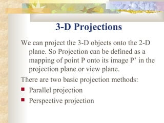
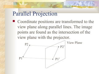
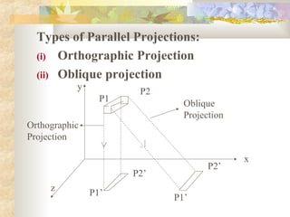
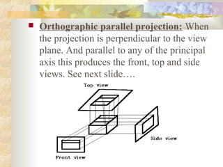
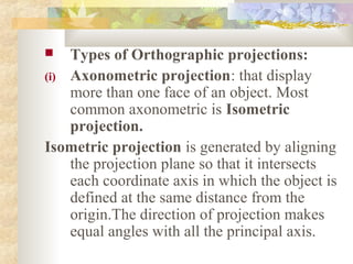
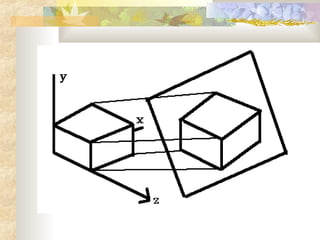
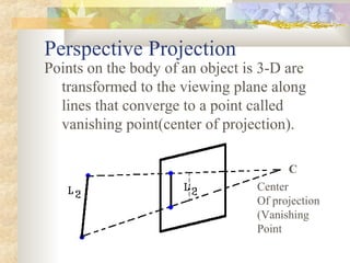
This document discusses 3D transformations and projections. It describes two main projection methods: parallel projection and perspective projection. Parallel projection preserves proportions but does not provide a realistic 3D representation. Perspective projection maps 3D points along converging lines to a vanishing point, resulting in foreshortening effects where objects appear smaller the farther they are from the viewing plane. The document outlines different types of parallel and perspective projections.
Transformation:
Transformations are a fundamental part of the computer graphics. Transformations are the movement of the object in Cartesian plane.
Types of transformation
Why we use transformation
3D Transformation
3D Translation
3D Rotation
3D Scaling
3D Reflection
3D Shearing
Transformation:
Transformations are a fundamental part of the computer graphics. Transformations are the movement of the object in Cartesian plane.
Types of transformation
Why we use transformation
3D Transformation
3D Translation
3D Rotation
3D Scaling
3D Reflection
3D Shearing
Comprehensive coverage of fundamentals of computer graphics.
3D Transformations
Reflections
3D Display methods
3D Object Representation
Polygon surfaces
Quadratic Surfaces
Ray casting is a rendering technique used in computer graphics and computational geometry.
It is capable of creating a three-dimensional perspective in a two-dimensional map.
Developed by scientists at the Mathematical Applications Group in the 1960.
it is considered one of the most basic graphics-rendering algorithms.
Ray casting makes use of the same geometric algorithm as ray tracing.
Advantage:
Ray casting is fast, as only a single computation is needed for every vertical line of the screen.
Compared to ray tracing, ray casting is faster, as it is limited by one or more geometric constraints.
his is one of the reasons why ray casting was the most popular rendering tool in early 3-D video games.
3D Display Methods:
In this section, we focus on a subgoals of realistic picture. This co-ordinate reference defines the position and orientation for the planeof the camera, as shown in next slide.This plane must be used to display a view of the object; its description has to transferred to thecamera reference co-ordinates and projected onto the selected display plane. Then we can displayobject in wire frame form or we can apply lighting and surface rendering techniques to shade thevisible surfaces
Computer Graphics and its applications, Elements of a Graphics, Graphics Systems: Video Display Devices, Raster Scan Systems, Random Scan Systems, Input devices.
: Introduction of Rendering, Raytracing, Antialiasing, Fractals
• Daroko blog (www.professionalbloggertricks.com)
• Presentation by Daroko blog, to see More tutorials more than this one here, Daroko blog has all tutorials related with IT course, simply visit the site by simply Entering the phrase Daroko blog (www.professionalbloggertricks.com) to search engines such as Google or yahoo!, learn some Blogging, affiliate marketing ,and ways of making Money with the computer graphic Applications(it is useless to learn all these tutorials when you can apply them as a student you know),also learn where you can apply all IT skills in a real Business Environment after learning Graphics another computer realate courses.ly
• Be practically real, not just academic reader
This is an introduction to 2D and 3 in computer graphics presented by daroko blog.
• Daroko blog (www.professionalbloggertricks.com)
• Presentation by Daroko blog, to see More tutorials more than this one here, Daroko blog has all tutorials related with IT course, simply visit the site by simply Entering the phrase Daroko blog (www.professionalbloggertricks.com) to search engines such as Google or yahoo!, learn some Blogging, affiliate marketing ,and ways of making Money with the computer graphic Applications(it is useless to learn all these tutorials when you can apply them as a student you know),also learn where you can apply all IT skills in a real Business Environment after learning Graphics another computer relate courses.ly
• Be practically real, not just academic reader
Notes 2D-Transformation Unit 2 Computer graphicsNANDINI SHARMA
Notes of 2D Transformation including Translation, Rotation, Scaling, Reflection, Shearing with solved problem.
Clipping algorithm like cohen-sutherland-hodgeman, midpoint-subdivision with solved problem.
In parallel projection, coordinate positions are
transformed to the view plane along parallel lines.
In perspective projection, object position are
transformed to the view plane along lines that
converge to a point called projection reference point
(center of projection)
2. 3-D Projections
We can project the 3-D objects onto the 2-D
plane. So Projection can be defined as a
mapping of point P onto its image P’ in the
projection plane or view plane.
There are two basic projection methods:
Parallel projection
Perspective projection
3. Parallel Projection
Coordinate positions are transformed to the
view plane along parallel lines. The image
points are found as the intersection of the
view plane with the projector.
View Plane
P2
P2’
P1 P1’
4. Parallel Projection preserves relative
proportions of objects.
Accurate views of the various sides of an
object are obtained with a parallel
projection, but this does not give us a
realistic representation of the appearance of
a 3-D object.
We can specify a parallel projection with a
projection vector that defines the direction
for the projection lines.
5. Types of Parallel Projections:
(i) Orthographic Projection
(ii) Oblique projection
y P2
P1 Oblique
Projection
Orthographic
Projection
x
P2’
P2’
z P1’ P1’
6. Orthographic parallel projection: When
the projection is perpendicular to the view
plane. And parallel to any of the principal
axis this produces the front, top and side
views. See next slide….
7. Types of Orthographic projections:
(i) Axonometric projection: that display
more than one face of an object. Most
common axonometric is Isometric
projection.
Isometric projection is generated by aligning
the projection plane so that it intersects
each coordinate axis in which the object is
defined at the same distance from the
origin.The direction of projection makes
equal angles with all the principal axis.
8.
9. Oblique projection: If the direction of
projection is not perpendicular to the
projection plane.
Types of Oblique Projection are:
(i) Cavalier- the direction of projection is
chosen so that there is no foreshortening
of lines perpendicular to the xy plane.
(ii) Cabinet- the direction of projection is
chosen so that lines perpendicular to the
xy planes are foreshortened by half their
lengths.
10. Perspective Projection
Points on the body of an object is 3-D are
transformed to the viewing plane along
lines that converge to a point called
vanishing point(center of projection).
C
Center
Of projection
(Vanishing
Point
11. So the distance of a line from the projection
plane determines its size on the projection
plane, i.e. the farther the line is from the
projection plane, the smaller its image on the
projection plane.
Characteristics:
(i) Vanishing Point: The lines that are
parallel to the viewing plane appear to
converge at a point called Vanishing point.
12. (ii) Perspective Foreshortening : Objects
that are farther from the viewing plane are
projected smaller in size than the objects
that are nearer to viewing plane.
(iii) View confusion : When we project
objects which are behind the center of
projection appears to be projected upside
down & backward onto the viewing plane.