Download as PDF, PPTX
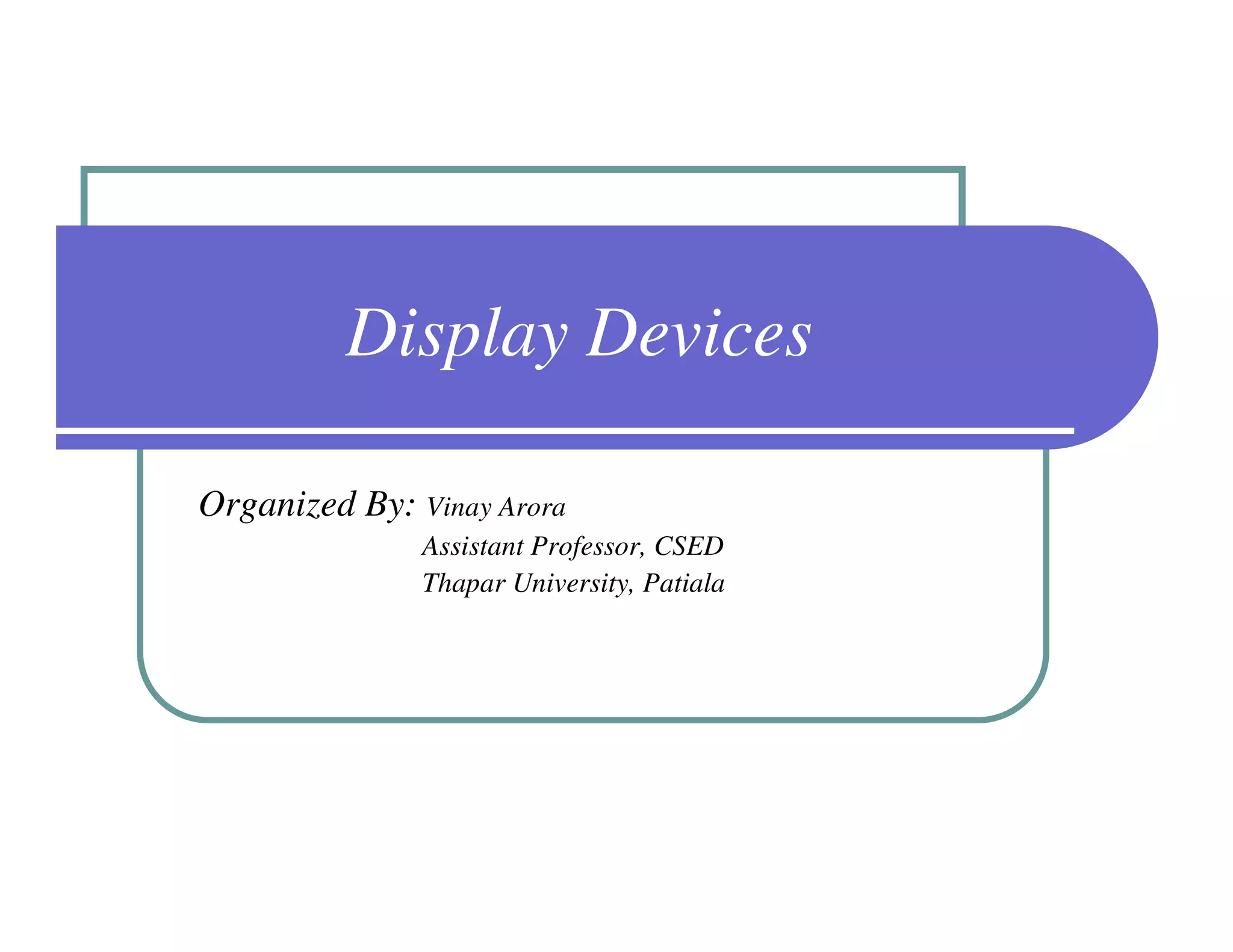

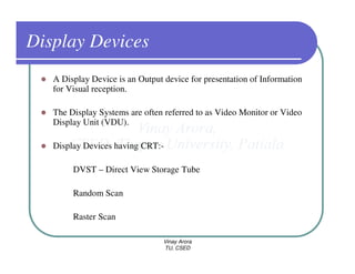
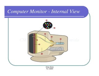
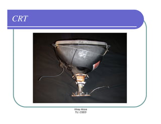
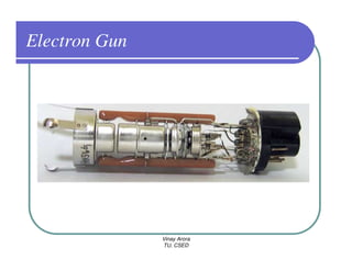
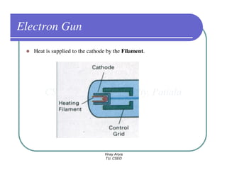
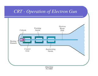
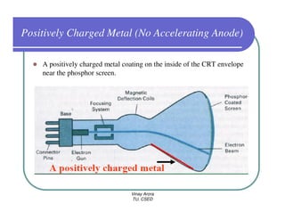
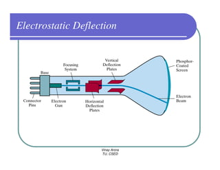
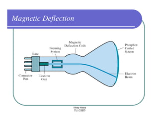
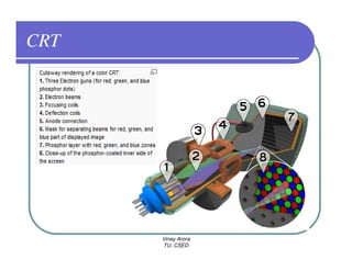

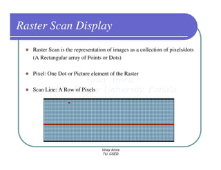
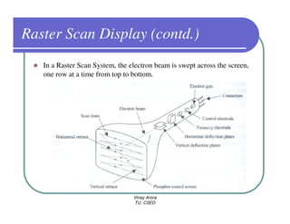
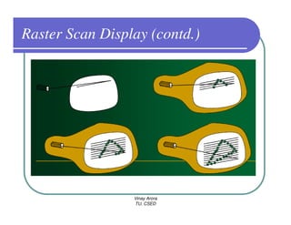
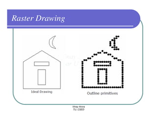
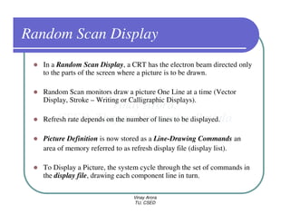
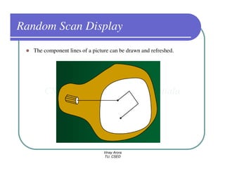
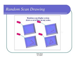
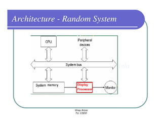
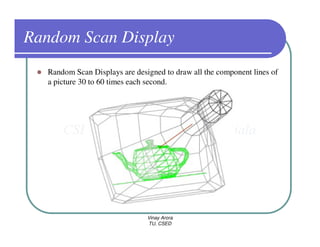
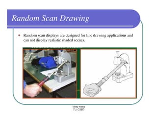
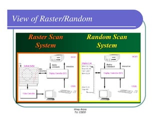
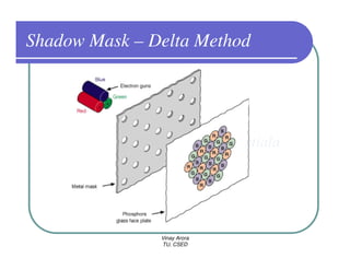
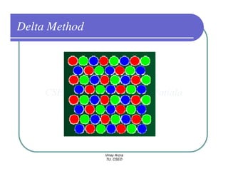
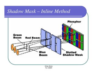
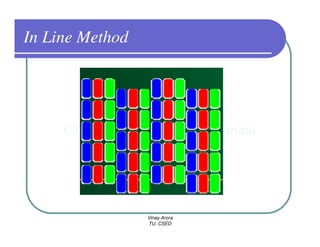
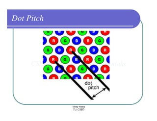

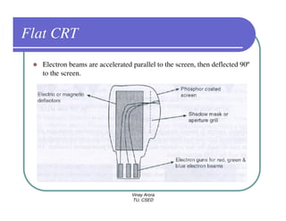
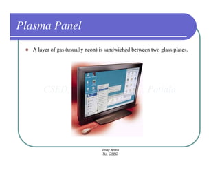

This document provides information about different types of display devices used in computer graphics. It discusses cathode ray tube (CRT) displays, including how CRTs work using an electron gun and accelerating electrons to excite phosphors to emit light. It describes raster scan displays, which draw images as a grid of pixels by sweeping an electron beam across the screen, and random scan displays, which draw images line by line. The document also covers color CRT displays using beam penetration or a shadow mask to combine red, green, and blue phosphors at each pixel location.